
Introduction
It makes the users possible to develop their own firmware. The characteristics are as follows:
- All the sources are written in C Language.
- The examples of how to control each part of the controller directly are provided.
NOTE : If you want to use Embedded C, you need the knowledge of software and hardware. If you are a beginner, we recommend you use Embedded C after learing the software and the hardware.
NOTE : If you use Embedded C, you cannot use RoboPlus since the controller’s firmware is changed. If you want to use RoboPlus again, you must restore the firmware using RoboPlus.
CM-510, CM-700
File Structure
- ../include : Necessary header files when using library
- ../src : Library sources
- ../lib : Library files
- ../example : Examples which can be executed in the controller
Getting Started
Install WinAVR
WinAVR is necessary for AVR programming.
WinAVR can be downloaded from the following website, and it is free-of-charge.
http://winavr.sourceforge.net/
The installation process is as below.
-
Select a language.
-
The initial window is as below.
-
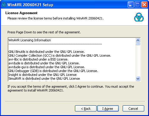
The window below is about the license agreement. You must agree to continue the installation.
-
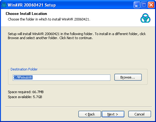
Select a folder for the installation, and then click “Next” button.
-
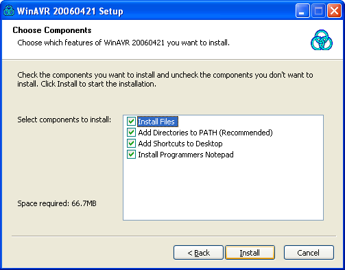
Select programs and environment options. If there are no specific reasons, it is recommended to install all in the list.
-
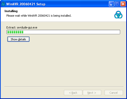
Start WinAVR installation.
-
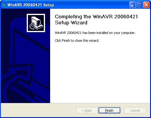
WinAVR installation is completed.
Install Atmel Studio
Atmel Studio provides users various Macro, Library, and comprehensive environment for easy programming.
Atmel Studio can be downloaded from the website below, and it is free-of-charge.
http://www.atmel.com/dyn/products/tools_card.asp?tool_id=2725
The installation procedure is as follows.
-
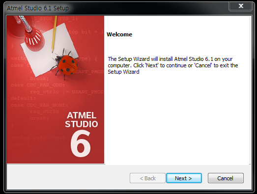
The initial window is as below.
-
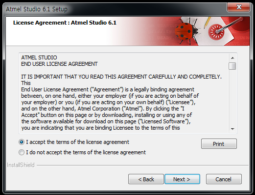
The window below is about license agreement. You must agree to continue the installation.
-
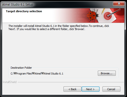
Select a folder for the installation, and then click “Next” button.
-
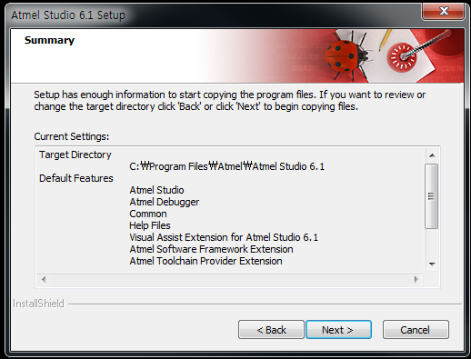
Click “Next” to continue the installation.
-
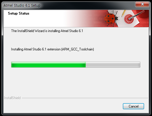
Start Atmel Studio installation.
-
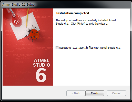
Atmel Studio installation is completed.
Environment Setting
If you want to use Embedded C, you must select the basic environment of the installed program.
- If Atmel Studio is installed after WinAVR, if it is not an exceptional case, you can do programming using Atmel Studio only.
- To run the examples DYNAMIXEL or other external devices maybe required in addition to the controller connected to the PC via serial cable.
-
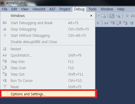
Click on Debug - Options and Settings.
-
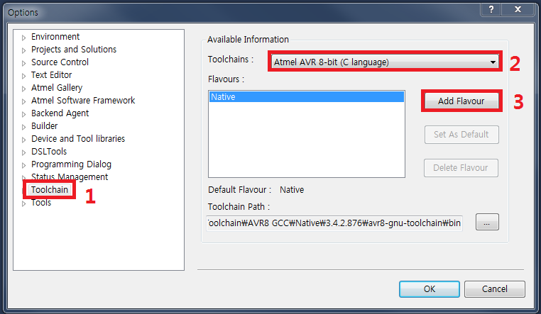
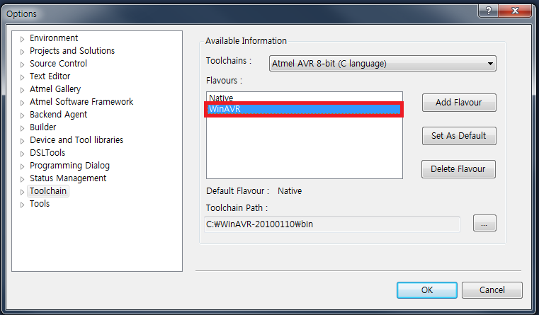
With the left mouse click select Toolchain. Selcts Atmel AVR 8-bit (C language). Click on Add Flavour.
-
Click on […] and select version’s 20100110 bin folder.
Ex) c:\WinAVR-20100110\bin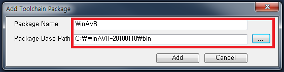
-
Select Win AVR then click on the OK button.
-
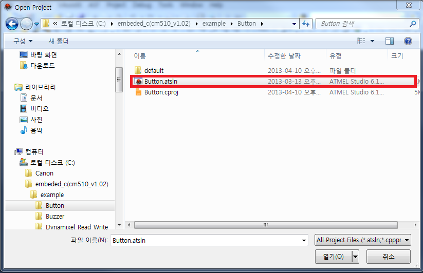
Click on File > Open > Project/Solution.
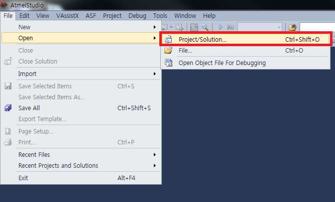
-
Select the example file then open it.
-
Click to select the c file located to the right of Solution Explorer. Click on Project -> Properties.
If Solution Explorer cannot be seen then select Solution Explorer from View.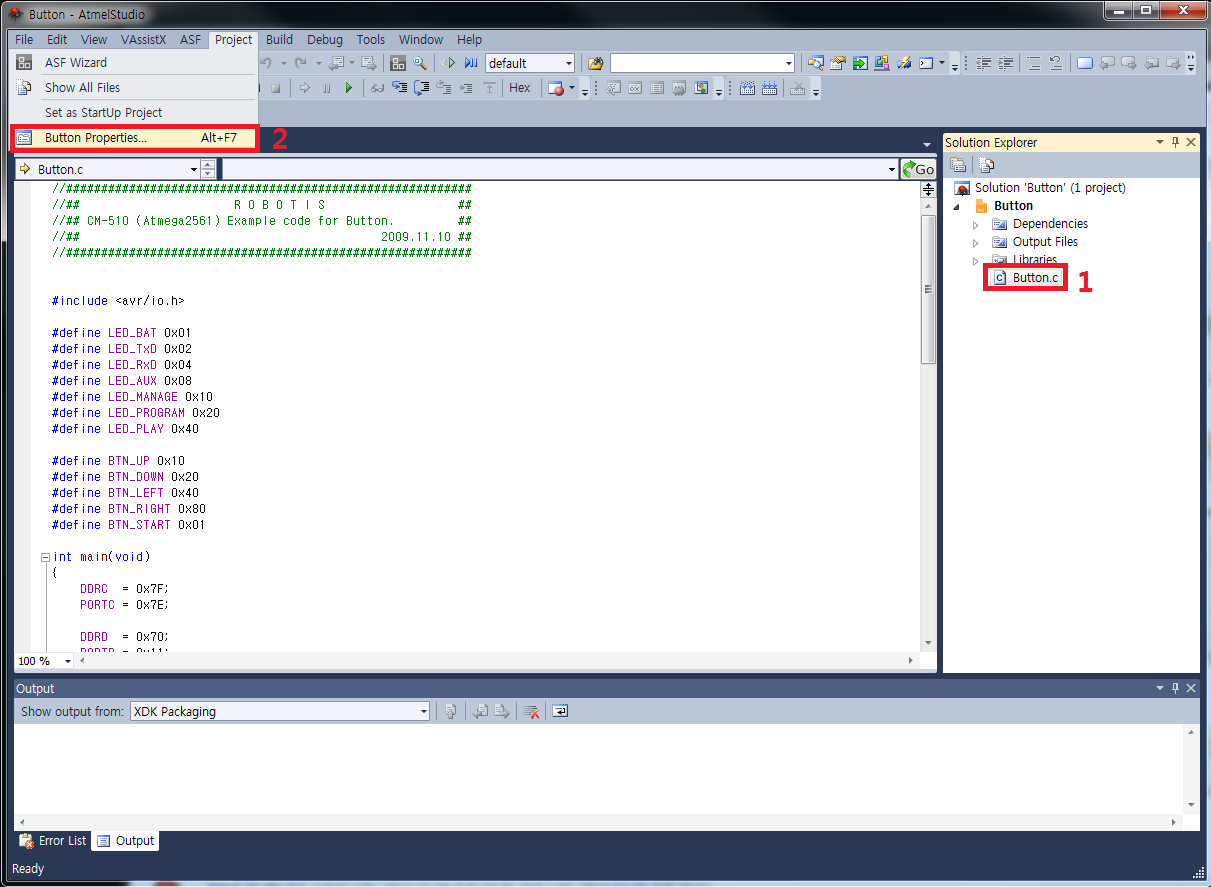
-
From the left hand menu click on Toolchain. Click on Directories. Click on the green + to add item.
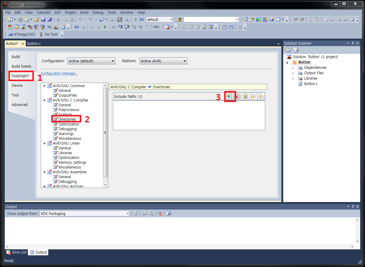
-
This will select the Include.
Ex) c:\embedded_c(cm700_v1.01)\include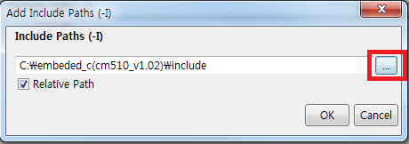
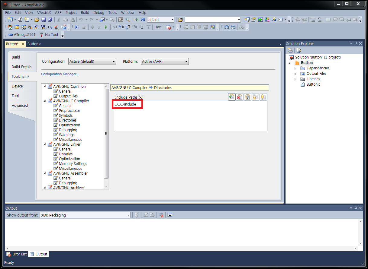
-
Its possible to verify in the include folder has been added.
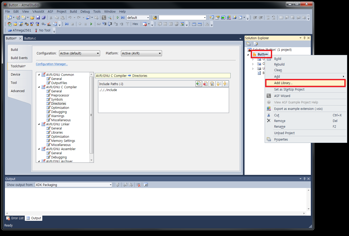
-
On Solution Explorer, from the right, click on the project file and click on Add Library.
-
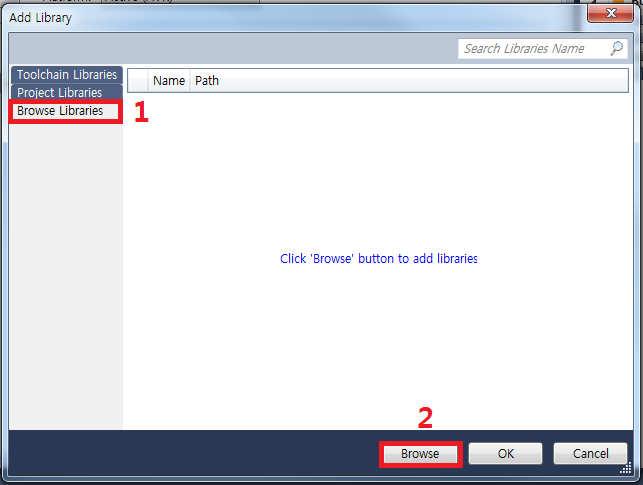
Click on Browse Libraries. Click on [Browse] on the lower right side.
-
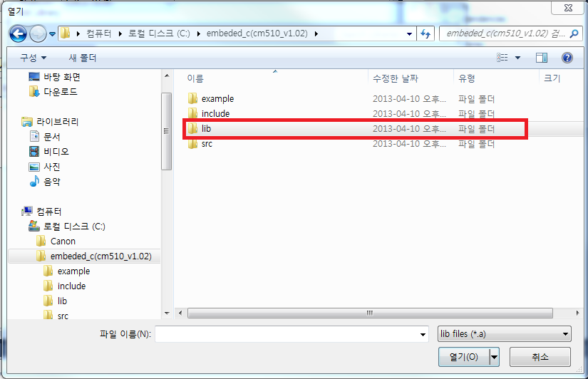
To select the library select and open the lib folder.
-
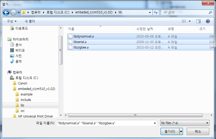
To add the 3 libraries select all and lick on [open] from the lower right.
-
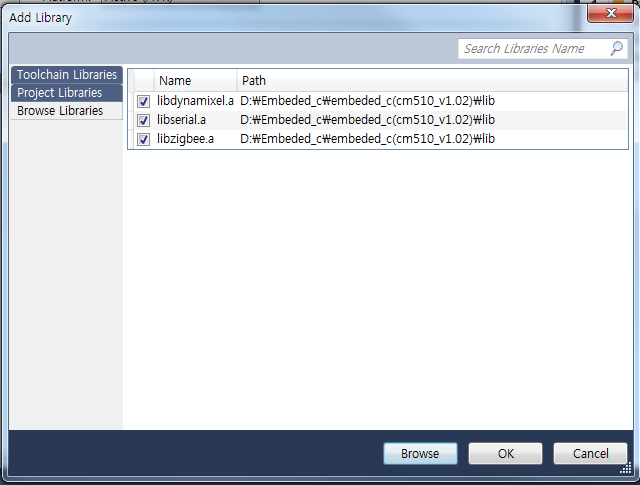
its possible to verify that all 3 libraries have been added.
-
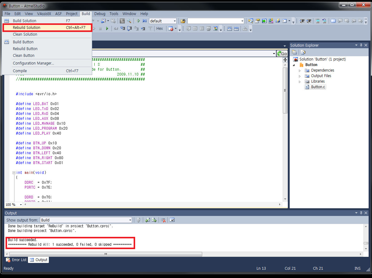
To compile click on Build -> Rebuild Solution and check for Build succeeded on the output window Build Succeeded.
Restore RoboPlus
The result made by Embedded C is a controller firmware (hex file). If you install it, you cannot use RoboPlus since the existing controller firmware is erased. If you want to use RoboPlus again, you must install the original controller firmware built-in from the factory. You can install the original controller firmware easily using RoboPlus Manager.
For more information, please refer to Firmware Restoration of RoboPlus Manager.
Programming
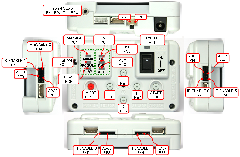
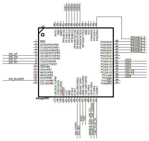
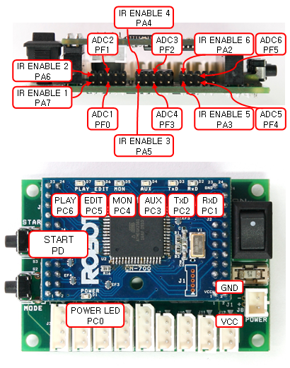
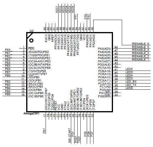
Hardware Port Map
The following hardware port map shows the hardware main pin functions of the controller.
Each port or internal functions can be controlled easily with macro function provided by Atmel Studio.
CM-510
| Port Name | Function |
|---|---|
| PORTF1 ~ PORTF6 | ADC |
| PORTD0 | Start Button |
| PORTD1 ~ PORTD2 | Tx, Rx |
| PORTA2 ~ PORTA7 | External Output ( 5 Pin Port) |
| PORTC0 ~ PORTC6 | Controller LED ( Status, Power ) |
| PORTB5 Buzzer | Control Port |
| PORTE4 ~ PORTE6 | Direction Button (U, D, L, R) |
| PORTD4 ~ PORTD6 | Communication Control Port |
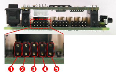
The external port pin composition of CM-510 is as below. You can check port 1 ~ port 6 by the scale marks on the external port. For more information, please refer to CM-510.
- As shown below, among 5 pins, No.3 ADC Pin is facing PORTF1 ~ PORTF6 of Micro Controller.
For example, ADC pin facing external port 3 as below is connected to PORTF3 of Micro Controller. - As shown below, among 5 pins, No.1 OUT Pin is facing PORTA2 ~ PORTA7 of Micro Controller.
For example, OUT pin facing external port 3 as below is connected to PORTA4 of Micro Controller.
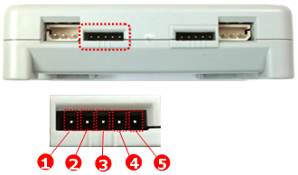
- OUT : 5V Output Available
- VCC (5V)
- ADC : Analogue signals of sensors made by users can be read.
- GND
- NC : Not used
CM-700
| Port Name | Function |
|---|---|
| PORTF1 ~ PORTF6 | ADC |
| PORTD0 | Start Button |
| PORTD2 ~ PORTD3 | Tx, Rx |
| PORTA2 ~ PORTA7 | External Output ( 5 Pin Port) |
| PORTC0 ~ PORTC6 | Controller LED ( Status, Power ) |
The external port pin composition of CM-700 is as below. You can check port 1 ~ port 6 by the letters written on the bottom of Sub-board.
For more information, please refer to CM-700.
- As shown below, among 5 pins, No.3 ADC Pin is facing PORTF1 ~ PORTF6 of Micro Controller.
- As shown below, among 5 pins, No.1 OUT Pin is facing PORTA2 ~ PORTA7of Micro Controller.
- OUT : 5V Output Available
- VCC (5V)
- ADC : Analogue signals of sensors made by users can be read.
- GND
- NC : Not used
Basic Programming
It explains how to make simple Embedded C examples on Atmel Studio.
Creating Project
The procedure of creating project is as below.
-
From the File menu select New -> Project.
-
Select GCC C Executable Project Name for template, This sets the items Location, Solution name. After setup click on [OK].
-
From the multiple devices list select ATmega2561 (ATmega128 for CM5). Click on [OK].
Creating Code and Compling
The following example is about the basic PORT I/O Control.
-
The following is code from the generated project.
#define F_CPU 16000000L #include <avr/io.h> #include <util/delay.h> int main(void) { DDRC = 0x7F; PORTC = 0x7E; while (1) { int i; for(i = 0; i <= 6; i++) { PORTC = ~(1 << i); _delay_ms(250); } } return 1; } -
From the Build menu click on [Build Solution] to run the build command.
-
When build succeeded message appears on the output window then compiling is complete. The firmware’s hex file can be found in the default folder from the project’s folder.
Downloading hex file
- To install the firmware on the controller, you must use RoboPlus Terminal and Boot Loader.
- For more information on the installation and the execution of firmware, please refer to Installing/Executing Program.
- If the firmware is installed normally, you can see all LEDs are turned on.
Boot Loader
Boot Loader makes the users possible to use the controller. Boot Loader cannot be erased by the users. If it is broken down, the controller cannot be used. Boot Loader is built-in on the controller when it is manufactured in the factory.
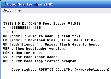
The available commands in Boot Loader can be found using “Help” command.
Install/Execute Program
Preparations for installing a firmware of the controller are as follows:
- Prepare a firmware (hex file) of the controller to be installed.
- Connect PC and the controller.
- Set the communication port by executing RoboPlus Terminal.
- Execute Boot Loader of the controller. (Please refer to how to enter Boot Loader.)
A firmware of the controller can be installed according to the procedure below.
-
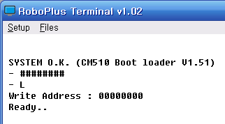
Input “L” command (or Load) in Boot Loader.
-
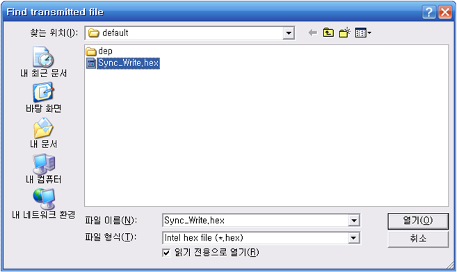
Select “Transmit File” in the Files menu of RoboPlus Terminal, and then select the prepared firmware. (hex file)
-
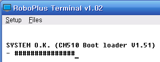
The file is transmitted. Please do not let the power of the controller turn off, and be careful the cable does not take off while the file is being transmitted.
-
When the file transmission is completed, you can execute the program using GO command.
- In case of inputting only “GO” command, the program is executed from 0 address.
- Like G [Address], if you input execution address (hexadecimal) after “G” command, the program is executed from the location.
Entering/Exiting Boot Loader
Entering Boot Loader
To enter into the boot loader, while pressing the ‘#’ button(Shift + 3), turn on the controller or press down the reset switch.
If you did correctly, following screen page will be shown.
Exiting Boot Loader
If the work is completed, you may exit by jumping to the desired address using “GO” command or by resetting the controller.
How to Use APP/SYS
The program start position can be set by APP/SYS command. Once the program start position is set, the program is executed on the program start position when the power is turned on or reset.
The memory map using Atmega2561 is as below.
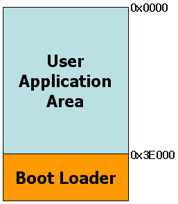
-
If you input APP command on the window after entering Boot Loader, User Application Area is executed first after the next reset.
(Most programs such as provided firmware, user program etc. start from 0 address, if there are no specific reasons.) -
If you input SYS command on the window after entering Boot Loader, Boot Loader is executed after the next reset.
(It is started as Boot Loader status, even if you do not press “#.”)
Examples
LED Control
Each LED of the controller can be controlled.
- Prepare
- CM-510 or 700
- Theory
- The micro controller can control the peripheral devices such as LED connected to the controller through I/O Port. You can control LEDs on the controller using this example.
- PORTC is used in this example. Please refer to Controller Port Map.
-
Source
PORTC = ~(1 << i); _delay_ms(250);- Turn on the LEDs in order by controlling PORTC.
- Result
- All LEDs will be turned on in order.
Button
Input of the button can be received.
- Prepare
- CM-510 or 700
- Theory
- Electronic signals of the devices connected to the controller can be read through I/O Port of the micro controller. You can see the status of pressed built-in switches through this example.
- PORTC and PORTE are used in this example. Please refer to Controller Port Map.
- Source
-
The Example of CM-510
  if(~PINE & BTN_UP)
   PORTC &= ~LED_MANAGE;
  else if(~PINE & BTN_DOWN)
   PORTC &= ~LED_AUX;
  else if(~PINE & BTN_LEFT)
   PORTC &= ~LED_PROGRAM;
  else if(~PINE & BTN_RIGHT)
   PORTC &= ~LED_PLAY;
  else if(~PIND & BTN_START)
   PORTC = ~(LED_BAT|LED_TxD|LED_RxD|LED_AUX|LED_MANAGE|LED_PROGRAM|LED_PLAY);
  else PORTC = LED_BAT|LED_TxD|LED_RxD|LED_AUX|LED_MANAGE|LED_PROGRAM|LED_PLAY;
You can see the pressed buttons through PORTD and PORTE, and LEDs can be turned on and off by controlling PORTC depending on the pressed buttons.
You can use macro function PIND and PINE to get input value through PORTD and PORTE.
PIND and PINE are 1 byte, and the pins of PORTD and PORTE are facing each bit.
Therefore, you can read the value of the certain pin through “&” operation etc. -
The Example of CM-700
  if(~PIND & BTN_START)
    PORTC = ~(LED_BAT|LED_TxD|LED_RxD|LED_AUX|LED_MANAGE|LED_PROGRAM|LED_PLAY);
  else PORTC = LED_BAT|LED_TxD|LED_RxD|LED_AUX|LED_MANAGE|LED_PROGRAM|LED_PLAY;
You can see the pressed buttons through PORTD, and LEDs can be turned on and off by controlling PORTC depending on the pressed buttons.
You can use macro fuction PIND to get the input value through PORTD.
PIND is 1 byte, and the pins of PORTD are facing each bit.
Therefore, you can read the value of the certain pin through “&” operation etc.
-
- Result
- If you press buttons, depending on pressed buttons, different LEDs are turned on.
Serial Communication
PC and the controller can perform serial communication.
- Prepare
- Serial cable for PC.
- The communication speed of the example is set to 57,600bps.
- Theory
- Serial communication is the basic method to show the value of the controller to users by transmitting to PC. You can try serial communication with the controller through this example.
-
Source
  serial_initialize(57600); // USART Initialize
  sei(); // set enable interrupt
This part is for initialization to use serial communication. The serial initialization function is included in serial library, and it is initialized if communication speed is transmitted by data.
In case of sei(), it is an internal command makes users possible to use “Interrupt.”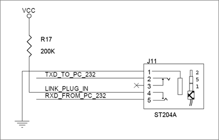
  unsigned char ReceivedData = getchar();
  if(ReceivedData == 'u')
  Value++;
  else if(ReceivedData == 'd')
  Value--;
  printf("%d\r\n", Value);
This part is for printing results by adding 1 if the received data is u, while by subtracting 1 if it is d.
The data is received using getchar() function; if the data is not received, it will wait. - Result
-
If you input “u”, the result is printed out by adding 1 to currently memorized number, while if you input “d”, it is printed out by subtracting 1.
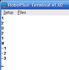
-
Buzzer
Buzzer on the controller can be used.
- Prepare
- CM-510 (CM-700 has no buzzer.)
- Theory
- Signals of the buzzer circuit can be controlled through I/O Port of the micro controller. The buzzer can play different musical notes by adjusting signal frequency.
- PORTB, PORTC and PORTD are used in this example. Please refer to Controller Port Map.
- The relationship between musical scale and frequency is as below.
-
Time is a reciprocal number of frequency. The conversion formula is as below.
Time(Sec) = 1 / (Frequency)
| Octave /Scale |
1 | 2 | 3 | 4 | 5 | 6 | 7 | 8 |
|---|---|---|---|---|---|---|---|---|
| C | 32.7032 | 65.4064 | 130.8128 | 261.6256 | 523.2511 | 1046.502 | 2093.005 | 4186.009 |
| C# | 34.6478 | 69.2957 | 138.5913 | 277.1826 | 554.3653 | 1108.731 | 2217.461 | 4434.922 |
| D | 36.7081 | 73.4162 | 146.8324 | 293.6648 | 587.3295 | 1174.659 | 2349.318 | 4698.636 |
| D# | 38.8909 | 77.7817 | 155.5635 | 311.1270 | 622.2540 | 1244.508 | 2489.016 | 4978.032 |
| E | 41.2034 | 82.4069 | 164.8138 | 329.6276 | 659.2551 | 1318.510 | 2637.020 | 5274.041 |
| F | 43.6535 | 87.3071 | 174.6141 | 349.2282 | 698.4565 | 1396.913 | 2793.826 | 5587.652 |
| F# | 46.2493 | 92.4986 | 184.9972 | 369.9944 | 739.9888 | 1479.978 | 2959.955 | 5919.911 |
| G | 48.9994 | 97.9989 | 195.9977 | 391.9954 | 783.9909 | 1567.982 | 3135.963 | 6271.927 |
| G# | 51.9130 | 103.8262 | 207.6523 | 415.3047 | 830.6094 | 1661.219 | 3322.438 | 6644.875 |
| A | 55.0000 | 110.0000 | 220.0000 | 440.0000 | 880.0000 | 1760.000 | 3520.000 | 7040.000 |
| A# | 58.2705 | 116.5409 | 233.0819 | 466.1638 | 932.3275 | 1864.655 | 3729.310 | 7458.620 |
| G | 61.7354 | 123.4708 | 246.9417 | 493.8833 | 987.7666 | 1975.533 | 3951.066 | 7902.133 |
Unit : Hz
- Source
-
This is an example for CM-510. This is not applicable for CM-700 because it has no buzzers.
if(~PIND & SW_START)
{
  PORTC = ~(LED_BAT|LED_TxD|LED_RxD|LED_AUX|LED_MANAGE|LED_PROGRAM|LED_PLAY);
  _delay_ms(1);
  PORTB |= 0x20;
  _delay_ms(1);
  PORTB &= ~0x20;
}
else
{
  PORTC = LED_BAT|LED_TxD|LED_RxD|LED_AUX|LED_MANAGE|LED_PROGRAM|LED_PLAY;
  PORTB &= ~0x20;
}
Pressed buttons are checked by PORTD, LEDs and Buzzers can be turned on and off by controlling PORTB and PORTC pursuant to pressed buttons.
You can use macro function PIND to get the input value through PORTD.
PIND is 1 byte, and the pins of PORTD are facing each bit.
Therefore, you can read the value of the certain pin through “&” operation etc.
If “Start” button is pressed, the buzzer makes sounds through PORTB as soon as all LEDs are turned on.
-
- Result
- All LEDs are turned on, and the buzzer makes sounds of same musical notes continuously while “Start” button is being pressed.
MIC
External sounds can be detected through MIC.
- Prepare
- CM-510 (CM-700 has no mic.)
- Theory
- If more than a certain level of sounds is detected on the MIC circuit, signals are made to I/O Port of the micro controller. External sounds can be detected by sensing the signals.
- PORTC and PORTD are used in the example. Please refer to Controller Port Map.
- Source
-
This is an example for CM-510. This is not applicable for CM-700 because it has no buzzers.
if(~PIND & MIC_SIGNAL)
{
  PORTC = ~(LED_BAT|LED_TxD|LED_RxD|LED_AUX|LED_MANAGE|LED_PROGRAM|LED_PLAY);
  _delay_ms(1000);
}
else PORTC = LED_BAT|LED_TxD|LED_RxD|LED_AUX|LED_MANAGE|LED_PROGRAM|LED_PLAY;
Pressed buttons are checked by PORTD, LEDs can be turned on or off by controlling PORTC pursuant to pressed buttons.
You can use macro function PIND to get the input value through PORTD.
PIND is 1 byte, and the pins of PORTD are facing each bit.
Therefore, you can read the value of the certain pin through “&” operation etc.
If the MIC signals are detected through PORTD, turn on all LEDs and wait for a second.
-
- Result
- When the MIC signals are detected, all LEDs are turned on and off for a second.
IR Sensor
Here you can learn how t o use the ADC of external ports. (This example is using the IR sensor for explanation. )
- Prepare
- CM-510 or 700
- IR Sensor (Connected to the external sensor No.1)
- Theory
- Analog signals can be changed into digital values through the micro controller. Through this example, the analog voltage values of external IR Sensor, Gyro Sensor etc. can be read.
- PORTA is used in the example. Please refer to Controller Port Map.
-
Source
serial_initialize(57600);
sei();
ADCSRA = (1 << ADEN) | (1 << ADPS2) | (1 << ADPS1); // ADC Enable, Clock 1/64div.
ADMUX = ADC_PORT_1; // ADC Port 1 Select
This part is for initialization to use serial communication. The serial initialization function is included in serial library, and the serial port is initialized if communication speed is transmitted by data.
In the case of sei(), it is an internal command makes users possible to use “Interrupt.”
Besides that, there is a register setting for ADC control. For the control, please refer to the datasheet of Atmega2561.
The datasheet can be downloaded at http://www.atmel.com.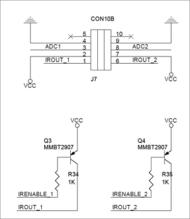
PORTA &= ~0x80; // ADC Port 1 IR ON

_delay_us(12); // Short Delay for rising sensor signal
ADCSRA |= (1 << ADIF); // AD-Conversion Interrupt Flag Clear
ADCSRA |= (1 << ADSC); // AD-Conversion Start

while( !(ADCSRA & (1 << ADIF)) ); // Wait until AD-Conversion complete

PORTA = 0xFC; // IR-LED Off

printf( "%d\r\n", ADC); // Print Value on USART
_delay_ms(50);
This part is for analyzing and transmitting the analog signals detected through PORTA.
First of all, turn on the IR LED 1 of PORTA, and then start converting the amount of received light into digital values.
When the conversion is complete, turn off the IR LED, and then transmit the values through serial communication. - Result
- When it is connected to PC in serial, IR sensor values are printed on the screen.
Read/Write Dynamixel
The location of DYNAMIXEL can be set and read.
- Prepare
- The controller and DYNAMIXEL are connected.
- This example is operated if DYNAMIXEL ID is 1.
- Theory
- DYNAMIXEL can be controlled by transmitting designated packet. The location of DYNAMIXEL can be controlled using provided library.
-
Source
unsigned short GoalPos[2] = {0, 1023};
//unsigned short wGoalPos[2] = {0, 4,095}; // for EX series
Like EX 106+, if an actuator belongs to the location range between 0 and 4,095, notes are applied to the upper line but not applied to the lower line.
serial_initialize(57600);
dxl_initialize( 0, DEFAULT_BAUDNUM ); // Not using device index
sei(); // Interrupt Enable
This part is for initialization to use serial communication. The serial initialization function is included in serial library, and the serial port is initialized if communication speed is transmitted by data.
In the case of sei(), it is an internal command makes users possible to use “Interrupt.”
In the case of dxl_initialize() function, communication environemnt of the controller is initialized if device index and communication speed are transmitted by data.
DEFAULT_BAUDNUM is 1.
If there are no specific reasons, device index is 0.// Check moving done bMoving = dxl_read_byte( id, P_MOVING ); CommStatus = dxl_get_result(); if( CommStatus == COMM_RXSUCCESS ) { if( bMoving == 0 ) { // Change goal position if( index == 0 ) index = 1; else index = 0; // Write goal position dxl_write_word( id, P_GOAL_POSITION_L, GoalPos[index] ); } PrintErrorCode(); // Read present position wPresentPos = dxl_read_word( id, P_PRESENT_POSITION_L ); printf( "%d %d\n",GoalPos[index], wPresentPos ); } else PrintCommStatus(CommStatus);This part describes that DYNAMIXEL is sent to certain location, and the current location is read at the same time.
First of all, if the current movement status has been read, and the motor is not moving, the movement command to the designated location can be carried on by dxl_write_word() function.
The data of dxl_write_word() function are respectively (the ID, address, and position values of connected DYNAMIXEL).
Later, the current location is read and transmitted by serial communication. - Result
- DYNAMIXEL is moved back and forth in the disgnated location, and the current location is printed through terminal.
Dynamixel Sync Control
Multiple DYNAMIXEL can be controlled by synchronization.
- Prepare
- The controller and DYNAMIXEL are connected.
- This example is operated when DYNAMIXEL ID is designated from 1 to 3 in order.
- Theory
- DYNAMIXEL can be controlled by transmitting designated packet. The location of DYNAMIXEL can be controlled using provided library.
-
Source
int AmpPos = 512;
//int AmpPos = 2048; // for EX series
Like EX 106+, if an actuator belongs to the location range between 0 and 4,095, notes are applied to the upper line but not applied to the lower line.
serial_initialize(57600);
dxl_initialize( 0, DEFAULT_BAUDNUM ); // Not using device index
sei(); // Interrupt Enable
This part is for initialization to use serial communication. The serial initialization function is included in serial library, and the serial port is initialized if communication speed is transmitted by data.
In the case of sei(), it is an internal command makes users possible to use “Interrupt.”
In the case of dxl_initialize() function, communication environment of the controller is initialized if device index and communication speed are transmitted by data.
DEFAULT_BAUDNUM is 1.
If there are no specific reasons, device index is 0.for( i=0; i < NUM_ACTUATOR; i++ ) { id[i] = i+1; phase[i] = 2*PI * (float)i / (float)NUM_ACTUATOR; } // Set goal speed dxl_write_word( BROADCAST_ID, P_GOAL_SPEED_L, 0 ); // Set goal position dxl_write_word( BROADCAST_ID, P_GOAL_POSITION_L, AmpPos ); _delay_ms(1000);This part is for calculation of the initial location and initialization of the location of each DYNAMIXEL. The speed of all DYNAMIXEL is set to the maximum level, and the location is set to the center using dxl_write_word() function.
// Make syncwrite packet
dxl_set_txpacket_id(BROADCAST_ID);
dxl_set_txpacket_instruction(INST_SYNC_WRITE);
dxl_set_txpacket_parameter(0, P_GOAL_POSITION_L);
dxl_set_txpacket_parameter(1, 2);
for( i=0; i < NUM_ACTUATOR; i++ )
{
  dxl_set_txpacket_parameter(2+3*i, id[i]);
  GoalPos = (int)((sin(theta+phase[i]) + 1.0) * (float)AmpPos);
  printf( "%d  ", GoalPos );
  dxl_set_txpacket_parameter(2+3*i+1, dxl_get_lowbyte(GoalPos));
  dxl_set_txpacket_parameter(2+3*i+2, dxl_get_highbyte(GoalPos));
}
dxl_set_txpacket_length((2+1)*NUM_ACTUATOR+4);
This part is for packet creation.  Please refer to DYNAMIXEL Packet Structure.
All connected actuator packets are created and transmitted.

printf( "\n" );

dxl_txrx_packet();
CommStatus = dxl_get_result();
if( CommStatus == COMM_RXSUCCESS )
PrintErrorCode();
else
PrintCommStatus(CommStatus);

theta += STEP_THETA;
if( theta > 2*PI )
theta -= 2*PI;
_delay_ms(CONTROL_PERIOD);
After receiving result packets, if there are errors, the error codes are printed.
If a value exceeds the calculated location boundary value, the increase/decrease direction is changed to the opposite. - Result
- Multiple DYNAMIXEL are moved back and forth in the designated location, and the current location is printed through terminal.
RC-100/ZIGBEE
The controller can be operated using RC-100.
- Prepare
- CM-510 or 700
- One pair of Zig-100/110
- RC-100
- Theory
- The controller can be controlled by RC100 remote controller equipped with Zig 100.
- PORTC and PORTD are used in this example. Please refer to Controller Port Map.
-
Source
PORTD &= ~0x80; //PORT_LINK_PLUGIN = 0;   // no pull up
PORTD &= ~0x20; //PORT_ENABLE_RXD_LINK_PC = 0;
PORTD |= 0x40; //PORT_ENABLE_RXD_LINK_ZIGBEE = 1;
zgb_initialize( 0 ); // Not using device index
sei(); // Interrupt Enable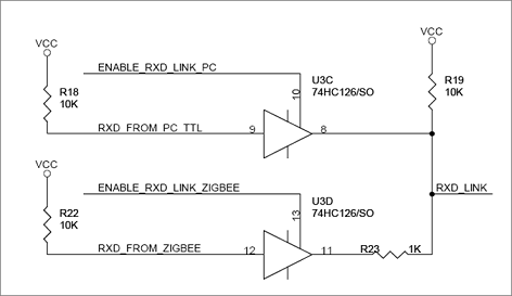
Set the environment to use ZigBee. The environment of PORTD must be set as below.
PORTD &= ~0x80; //PORT_LINK_PLUGIN = 0;   // no pull up
PORTD &= ~0x20; //PORT_ENABLE_RXD_LINK_PC = 0;
PORTD |= 0x40; //PORT_ENABLE_RXD_LINK_ZIGBEE = 1;
This part is for initialization to use ZigBee communication. The initialization function is included in Zigbee library, and the Zigbee is initialized if device index is transmitted by data.
If there are no specific cases, device index is 0.
In the case of sei(), it is an internal command makes users possible to use “Interrupt.”if(zgb_rx_check() == 1) { RcvData = zgb_rx_data(); if(RcvData & RC100_BTN_1) PORTC &= ~LED_MANAGE; else PORTC |= LED_MANAGE; if(RcvData & RC100_BTN_2) PORTC &= ~LED_PROGRAM; else PORTC |= LED_PROGRAM; if(RcvData & RC100_BTN_3) PORTC &= ~LED_PLAY; else PORTC |= LED_PLAY; }The received data by Zigbee Module can be read using zgb_rx_data() function.
If the received packet is RC-100 button, LEDs are turned on or off by controlling PORTC pursuant to pressed buttons of RC-100.CAUTION : Due to the UART sharing, there will be a system collision when you use both ZIGBee and serial communication library at the same time. If you want to use both of them at once, you must modify the source properly in advance.
- Result
- If Zigbee is connected normally, LEDs are turned on and off whenever the buttons of RC-100 is pressed.