Introduction
CM-550
Specifications
| Item | Specifications |
|---|---|
| Weight | 58.8 [g] |
| MCU | ARM Cortex-M4 (168 [MHz], 32 [Bit]) |
| Operating Voltage | Battery : 6.5 ~ 15 [V], Recommended 11.1 [V] (Li-PO 3cell) SMPS : 6.5 ~ 15 [V], Recommended 12.0 [V] Micro USB : 4.75 ~ 5.25 [V], Recommended 5.0 [V] |
| Current Consumption | Standby : 50 [mA] Port 1 ~ 2 I/O Max : 0.5 [A] Port 3 ~ 5 I/O Max : 0.02 [A] Total : 10 [A] (Fuse) |
| Operating Temperature | -5 ~ 70 [°C] |
| Communication Module | BLE Slave Module |
| Internal I/O Devices | Buttons : 2 (MODE, START) Mic (Sound Detection) : 1 Buzzer : 1 Voltage Sensor : 1 Gyro Accelerometer : 1 Temperature Sensor : 1 RGB LED : 3 |
| External I/O Devices | ROBOTIS 5 Pin Port : 5 (Servo Motor / IR Sensor / Temperature & Humidity Sensor : Use Port 1 or 2) |
| DYNAMIXEL Port | X-series TTL (half-duplex asynchronous) 3-Pin connector: 6 |
| DYNAMIXEL Protocol (Packet) | Protocol 2.0 |
XL-320 is not compatible with CM-550.
![]()
DANGER
(Ignoring these warnings may cause serious injury or death)
- Never place items containing water, flammables/open flames, or solvents near the product.
- Never place fingers, arms, toes, and other body parts near product during operation.
- Cease operation and remove power from the product if the product begins to emit strange odors, noises, or smoke.
- Keep product out of reach of children.
- Check input polarity before installing or energizing wiring or cables.
![]()
CAUTION
(Ignoring these warnings may cause mild injury or damage to the product)
- Always comply with the product’s offical operating environment specifications including input voltage, current, and operating temperature.
- Do not insert blades or other sharp objects during product operation.
![]()
ATTENTION
(Ignoring these warnings may cause minor injury or damage to the product)
- Do not disassemble or modify the product.
- Do not drop the product or apply strong impacts.
- Do not connect or disconnect DYNAMIXEL cables while power is being supplied.
Control Table
Control Table consists of data regarding the current status and operation of controller. The user can control controller by changing data of Control Table via Instruction packet.
-
EEPROM and RAM
Data in RAM area is reset to initial values whenever the power is turned on while data in EEPROM area is kept once values are set even if the power is turned off. -
Address
Represents the location of data. To read from or write data to the control table the user should assign the correct address in the Instruction packet. -
Access
Controller has two kinds of data: Read-only data, used mainly for sensing, and read-and-write data used for driving. -
Initial Value
In case of data in the EEPROM Area, the initial values on the right side of the below Control Table are the factory default settings.
In case of data in the RAM Area, the initial values on the right side of the following control table are the ones when the power is turned on. -
Size
The Size of data varies from 1 ~ 4 bytes depend on their usage. Please check the size of data when updating the data with an Instruction Packet.
CM-550 Control Table
| Area | Address | Size[Byte] | Data Name | Access | Default Value | Range | Unit | Value | Description |
|---|---|---|---|---|---|---|---|---|---|
| EEPROM | 0 | 2 | Model Number | R | 450 | - | - | - | Model Number |
| EEPROM | 6 | 1 | Version of Firmware | R | - | 0 ~ 255 | - | - | Firmware Version |
| EEPROM | 7 | 1 | ID | R | 200 | - | - | - | Controller ID |
| EEPROM | 11 | 1 | Bootloader Version | R | - | 0 ~ 255 | - | - | Bootloader Version |
| EEPROM | 12 | 1 | Baud Rate (DYNAMIXEL) | RW | 3 | 0 ~ 7 | - | 0 : 9600 bps 1 : 57600 bps 2 : 115200 bps 3 : 1 Mbps 4 : 2 Mbps 5 : 3 Mbps 6 : 4 Mbps 7 : 4.5 Mbps |
DYNAMIXEL Communication Baud Rate Note that, If a baudrate of DYNAMIXEL is 57600 bps while CM550 is on boot, the baudrate of DYNAMIXEL will be automatically set to 1 M bps. Baud rates other than 57600 bps will stay on boot time. |
| EEPROM | 13 | 1 | Baud Rate (UART) | RW | 1 | 0 ~ 7 | - | See Address 12 | Emebedded UART Comunication Baud Rate |
| EEPROM | 15 | 1 | Contorller Direction | RW | 0 | 0 ~ 1 | - | 0 : Vertical 1 : Horizontal |
Set the value (Vertical or Horizontal) by the direction of the controller |
| EEPROM | 16 | 1 | Temperature Limit | RW | 60 | -20 ~ 100 | °C | - | Set the value to limit temperature. In excessing this value, DYNAMIXEL connected with a controller will not operate. |
| RAM | 20 | 1 | Bypass Port |
R | 0 | 0 ~ 2 | - | 0 : BLE 1 : UART 2 : USB |
The communication port to bypass with DYNAMIXEL port. |
| RAM | 21 | 1 | Mode Number | RW | 2 | 0 ~ 4 | - | 0 : IDLE 1 : Task Play 2 : Manage 3 : Bootloader 4 : Reboot |
- Set IDLE (0), Task Play(1) or Manage(2) to change operating mode. - Set Bootloader(3) to run a boot loader - Use Reboot(4) to reboot a controller. |
| RAM | 22 | 1 | Dxl Power Switch | RW | 1 | 0 ~ 1 | - | 0 : False 1 : True |
Power On (True) / Off (False) DYNAMIXEL. In detecting an error, it sets the value to ‘0’ from ‘1’ (1: Default) |
| RAM | 23 | 2 | Error Code | R | 0 | 0 ~ 65535 | - | - | Error codes when a controller detects an error. |
| RAM | 26 | 1 | Start Button Status | R | 0 | 0 ~ 3 | - | 0 : None is pressed 1 : START button pressed 2: MODE button pressed 3. Both START and MODE buttons are pressed |
Button Status. In pressing either Start or Mode button, this value will be changed depending on what you press. |
| RAM | 27 | 1 | BLE Check | R | - | 0 ~ 1 | - | 0 : False 1 : True |
0 is set when BLE module in a controller is missing or not operating. |
| RAM | 28 | 1 | Button Released Event | R | 1 | 0 ~ 1 | - | 0 : False 1 : True |
When Start button is released from holding down, it returns True, and returns False after controller reads the event. |
| RAM | 29 | 2 | Button Pressed ms | R | 1 | 0 ~ 65535 | ms | - | The value will increase at ms unit in holding down a button. |
| RAM | 31 | 1 | Button Pressed Sec | RW | 1 | 0 ~ 255 | Sec | - | The value will increase at sec unit in holding down a button. |
| RAM | 35 | 1 | Task Print Port | RW | 0 | 0 ~ 2 | - | 0 : BLE 1 : UART 2 : USB |
Select a port in order to monitor a serial output with R+ Task software. |
| RAM | 36 | 1 | App Port | RW | 0 | 0 ~ 1 | - | 0 : BLE 1 : UART |
- Set BLE (0) to use an embedded Bluetooth module. - Set UART (1) to use an external port supporting UART comunication |
| RAM | 37 | 1 | App Connected | R | 0 | 0 ~ 1 | - | 0 : False 1 : True |
App status check if a smart device is connected. |
| RAM | 39 | 1 | Num of Dxl | R | 0 | 0 ~ 255 | - | - | - The number of connected DYNAMIXEL with a controller. - Update the status of connected DYNAMIXELs using Scan DXL (Address 40) |
| RAM | 40 | 1 | Scan Dxl | RW | 0 | 0 ~ 1 | - | 0 : False 1 : True |
Search connected DYNAMIXELs via Protocol 1.0 / 2,0 and update the status of connected DYNAMIXELs. |
| RAM | 41 | 1 | Dxl Torque | RW | 0 | 0 ~ 3 | - | 0 : NONE 1 : OFF, Busy 2 : ON 3 : REBOOT |
Enable (or disable) a torque of connected DYNAMIXEL, or to reboot. - Be sure to wait for few until the value is read and turned back to ‘0’. |
| RAM | 43 | 1 | Remote Port | RW | 0 | 0 ~ 2 | - | 0 : BLE 1 : UART 2 : USB |
Select a port for use of remote controller. (Default: BLE (0)) |
| RAM | 51 | 4 | Print Number | W | 0 | -32768 ~ 32767 | - | - | 4 bytes signed value for serial monitor output without a newline character. |
| RAM | 55 | 4 | Print Number LF | W | 0 | -32768 ~ 32767 | - | - | 4 bytes signed value for serial monitor output with a newline character. |
| RAM | 59 | 2 | Transmitting Remocon Data | RW | 0 | 0 ~ 65535 | - | - | Remote data to transmit to Remote Port (Address 43) |
| RAM | 61 | 2 | Received Remocon Data | R | 0 | 0 ~ 65535 | - | - | Remote data received to Remote Port (Address 43) |
| RAM | 63 | 1 | Remocon Data Arrived | R | 0 | 0 ~ 1 | - | 0 : False 1 : True |
Check newly arrived remote data. |
| RAM | 64 | 1 | Motion Play Speed | W | 100 | 20 ~ 200 | - | - | Adjust motion speed from 20 to 100 % |
| RAM | 66 | 2 | Motion Index Number | RW | 0 | 0 ~ 65535 | - | 0 : Motion stop using an Exit Motion unit. 1~65532 : Motion play with a selected page. 65533 : Immediate Motion stop 65534 : Motion stop at the current Key Frame 65535 : Motion stop at the current unit. |
Play a specific motion or to stop a motion currently played. |
| RAM | 68 | 1 | Motion Play Status | R | 0 | 0 ~ 1 | - | 0 : False 1 : True |
Check Motion Play status |
| RAM | 69 | 2 | Motion Next Page | RW | 0 | 0 ~ 65535 | - | 0~65534 : Page to move next. 65535 : None page. |
Create flexible and smooth motion profile, which keep a motion played without a motion stop, by reading a next page to expect the next motion movement. |
| RAM | 71 | 2 | Motion Count | R | - | 0 ~ 1023 | - | - | The number of motion page saved in FLASH memory. |
| RAM | 73 | 1 | 128 ms Timer Value | RW | 0 | 0 ~ 255 | 128 ms | - | 128 ms countdown timer |
| RAM | 74 | 2 | 1 ms Timer Value | RW | 0 | 0 ~ 65535 | ms | - | 1 ms countdown timer |
| RAM | 77 | 1 | Random Number | RW | 0 | 0 ~ 255 | - | - | Generate random number between 0 to a specific number |
| RAM | 84 | 1 | Buzzer Index | RW | 0 | 0 ~ 255 | - | - | - In melody mode, 0 to 25 melody will be played - In scale mode, 0 to 51 scale will be played |
| RAM | 85 | 1 | Buzzer Time | RW | 0 | 0 ~ 255 | 0.1 sec | - | - 0 to 50: Scale Mode. Play scale for 0.3 to 5.0 sec; Unit : 0.1 s - 50 to 254: Scale Mode. Play scale for 5 sec. - 255 : Enter Melody Mode. |
| RAM | 86 | 1 | Sound Detected Count | RW | 0 | 0 ~ 255 | - | - | Detect sound from mic and count the number of detected sound. |
| RAM | 87 | 1 | Sound Detecting Count | R | 0 | 0 ~ 255 | - | - | Detect sound in real time from mic. |
| RAM | 88 | 1 | Low Battery Sound Enable | RW | 1 | 0 ~ 1 | - | 0 : False 1 : True |
Enable / disable a low battery alarm. |
| RAM | 89 | 1 | Voltage | R | - | 0 ~ 255 | 0.1 V | Read input Voltage to a controller | |
| RAM | 90 | 1 | Temperature | R | - | -20 ~ 100 | °C | Read a controller’s temperature | |
| RAM | 91 | 1 | Red LED | RW | 0 | 0 ~ 1 | - | 0 : Off 1 : On |
On/Off Controller’s Aux Red |
| RAM | 92 | 1 | Green LED | RW | 0 | 0 ~ 1 | - | 0 : Off 1 : On |
On/Off Controller’s Aux Green LED |
| RAM | 93 | 1 | Blue LED | RW | 0 | 0 ~ 1 | - | 0 : Off 1 : On |
On/Off Controller’s Aux Blue LED |
| RAM | 102 | 2 | Roll | R | 0 | -18000 ~ 18000 | 0.01 degree | - | IMU Roll axis data |
| RAM | 104 | 2 | Pitch | R | 0 | -9000 ~ 9000 | 0.01 degree | - | IMU Pitch axis data |
| RAM | 106 | 2 | Yaw | R | 0 | -18000 ~18000 | 0.01 degree | - | IMU Yaw axis data |
| RAM | 108 | 2 | Gyro X | R | 0 | -32768 ~ 32767 | 0.01 degree/s | - | IMU Gyro X axis data |
| RAM | 110 | 2 | Gyro Y | R | 0 | -32768 ~ 32767 | 0.01 degree/s | - | IMU Gyro Y axis data |
| RAM | 112 | 2 | Gyro Z | R | 0 | -32768 ~ 32767 | 0.01 degree/s | - | IMU Gyro Z axis data |
| RAM | 114 | 2 | Acc X | R | 0 | -32768 ~ 32767 | 0.01 G | - | IMU Accel X axis data |
| RAM | 116 | 2 | Acc Y | R | 0 | -32768 ~ 32767 | 0.01 G | - | IMU Accel Y axis data |
| RAM | 118 | 2 | Acc Z | R | 0 | -32768 ~ 32767 | 0.01 G | - | IMU Accel Z axis data |
| RAM | 120 | 4 | micros | R | 0 | -2147483648 ~ 2147483647 | us | - | 1 us counter inside the controller |
| RAM | 124 | 4 | millis | R | 0 | -2147483648 ~ 2147483647 | ms | - | 1 ms counter inside the controller |
| EEPROM | 139 | 1 | BLE Signal Power | RW | 2 | 0 ~ 9 | - | 0: unknown (Fail to read BLE Signal Power Data) 1: +4dB 2: 0dB 3: -4dB 4: -8dB 5: -12dB 6: -16dB 7: -20dB 8: -30dB 9: -40dB |
Embeded BLE’s signal strenth. |
| EEPROM | 144 | 12 | BLE MAC Address | R | 0 | - | - | - | Shows to BLE Module’s MAC address inside the controller |
| RAM | 156 | 1 | USB OTG Connected | R | 0 | 0 ~ 1 | - | - | - 0: USB OTG cable is disconnected. - 1: USB OTG cable is connected. |
| RAM | 157 | 1 | Rpi Connected | R | 0 | 0 ~ 1 | - | - | - 0: RPI board is disconnected. - 2: RPI board is connected |
| RAM | 164 | 1 | Rpi IP 1 | R | 0 | 0 ~ 255 | - | - | The first IP field of connected RPI board |
| RAM | 165 | 1 | Rpi IP 2 | R | 0 | 0 ~ 255 | - | - | The second IP field of connected RPI board |
| RAM | 166 | 1 | Rpi IP 3 | R | 0 | 0 ~ 255 | - | - | The third IP field of connected RPI board |
| RAM | 167 | 1 | Rpi IP 4 | R | 0 | 0 ~ 255 | - | - | The fourth IP field of connected RPI board |
| RAM | 199 | 1 | Offset Control | RW | 0 | 0 ~ 3 | - | 0 : None 1 : Read 2 : Write 3 : Clear |
Save (or read) motion offset data to FLASH memory. Using Clear (3), both saved Motion Offset and Joint Offset will be cleared to 0. |
| RAM | 390 | 1 | Module Category 1 | RW | 0 | 0 ~ 18 | - | 0 : None 1 : Wheel Velocity 2 : Servo Position 3 : Servo Speed 4 : IR Sensor 5 : DMS 6 : Touch Sensor 7 : LED Module 8 : User Device 9 : Temperature Sensor 11 : Magnetic Sensor 12 : Motion Sensor 13 : Color Sensor 14 : Moisture Sensor 15 : Temperature(Moisture) 16 : Brightness Sensor 17 : RED Brightness of RED/BLUE LED Board 18 : BLUE Brightness of RED/BLUE LED Board |
- Used to manually set a desired mode for peripherals in use of 5 pin ports. - In setting the value ‘0: None’ and reading data from the OLLO ports, the value will be automatically set depending on the feature of the used address with the ports. |
| RAM | 392 | 1 | Module Category 2 | RW | 0 | 0 ~ 18 | - | See Address 390 | See Address 390 |
| RAM | 394 | 1 | Module Category 3 | RW | 0 | 0 ~ 16 | - | 0 : None 5 : DMS 6 : Touch Sensor 7 : LED Module 8 : User Device 9 : Temperature Sensor 11 : Magnetic Sensor 12 : Motion Sensor 13 : Color Sensor 16 : Brightness Sensor |
See Address 390 |
| RAM | 396 | 1 | Module Category 4 | RW | 0 | 0 ~ 16 | - | See Address 394 | See Address 390 |
| RAM | 398 | 1 | Module Category 5 | RW | 0 | 0 ~ 16 | - | See Address 394 | See Address 390 |
| RAM | 400 | 2 | Port 1 Wheel Velocity | RW | 0 | 0 ~ 2047 | - | CCW : 0~1023 CW : 1024~2047 |
Set to DC motor mode and to adjust PWM output to control the velocity of a motor. |
| RAM | 402 | 2 | Port 2 Wheel Velocity | RW | 0 | 0 ~ 2047 | - | See Address 400 | |
| RAM | 404 | 2 | Port 1 Servo Position | RW | 0 | 0 ~ 1023 | - | 0~1023 | - Set to Servo mode and to control the position of the motor horn. - 0–300 ° Only - The center of the horn position is 512. |
| RAM | 406 | 2 | Port 2 Servo Position | RW | 0 | 0 ~ 1023 | - | See Address 404 | |
| RAM | 408 | 2 | Port 1 Servo Speed | RW | 0 | 0 ~ 1023 | - | CCW : 0~1023 CW : 1024~2047 |
Configure the moving velocity in the Servo mode. |
| RAM | 410 | 2 | Port 2 Servo Speed | RW | 0 | 0 ~ 1023 | - | See Address 408 | |
| RAM | 415 | 2 | Port 1 IR Sensor | R | 0 | 0 ~ 1023 | - | - | Read value from an IR sensor |
| RAM | 417 | 2 | Port 2 IR Sensor | R | 0 | 0 ~ 1023 | - | - | See Address 415 |
| RAM | 419 | 2 | Port 1 DMS Sensor | R | 0 | 0 ~ 1023 | - | - | Read value from an DMS. |
| RAM | 421 | 2 | Port 2 DMS Sensor | R | 0 | 0 ~ 1023 | - | - | See Address 419 |
| RAM | 423 | 2 | Port 3 DMS Sensor | R | 0 | 0 ~ 1023 | - | - | See Address 419 |
| RAM | 425 | 2 | Port 4 DMS Sensor | R | 0 | 0 ~ 1023 | - | - | See Address 419 |
| RAM | 427 | 2 | Port 5 DMS Sensor | R | 0 | 0 ~ 1023 | - | - | See Address 419 |
| RAM | 429 | 1 | Port 1 Touch Sensor | R | 0 | 0 ~ 1 | - | 0 : False 1 : True |
Read value from a touch sensor. |
| RAM | 430 | 1 | Port 2 Touch Sensor | R | 0 | 0 ~ 1 | - | See Address 429 | See Address 429 |
| RAM | 431 | 1 | Port 3 Touch Sensor | R | 0 | 0 ~ 1 | - | See Address 429 | See Address 429 |
| RAM | 432 | 1 | Port 4 Touch Sensor | R | 0 | 0 ~ 1 | - | See Address 429 | See Address 429 |
| RAM | 433 | 1 | Port 5 Touch Sensor | R | 0 | 0 ~ 1 | - | See Address 429 | See Address 429 |
| RAM | 434 | 1 | Port 1 LED Module | RW | 0 | 0 ~ 3 | - | 0 : Both OFF 1 : Left OFF, Right ON 2 : Left ON, Right OFF 3 : Both ON |
Control a LED module |
| RAM | 435 | 1 | Port 2 LED Module | RW | 0 | 0 ~ 3 | - | See Address 434 | See Address 434 |
| RAM | 436 | 1 | Port 3 LED Module | RW | 0 | 0 ~ 3 | - | See Address 434 | See Address 434 |
| RAM | 437 | 1 | Port 4 LED Module | RW | 0 | 0 ~ 3 | - | See Address 434 | See Address 434 |
| RAM | 438 | 1 | Port 5 LED Module | RW | 0 | 0 ~ 3 | - | See Address 434 | See Address 434 |
| RAM | 439 | 2 | Port 1 User Device | RW | 0 | 0 ~ 1023 | - | OUTPUT 0 : Left 5V, Right 5V 1 : Left 5V, Right 0V 2 : Left 0V, Right 5V 3 : Left 0V, Right 0V INPUT 0 : 0V 1023 : 5V |
- OUTPUT: Control Two output pins. - INPUT: Analog Input. |
| RAM | 441 | 2 | Port 2 User Device | RW | 0 | 0 ~ 1023 | - | See Address 439 | See Address 439 |
| RAM | 443 | 2 | Port 3 User Device | RW | 0 | 0 ~ 1023 | - | See Address 439 | See Address 439 |
| RAM | 445 | 2 | Port 4 User Device | RW | 0 | 0 ~ 1023 | - | See Address 439 | See Address 439 |
| RAM | 447 | 2 | Port 5 User Device | RW | 0 | 0 ~ 1023 | - | See Address 439 | See Address 439 |
| RAM | 449 | 1 | Port 1 Temperature Sensor | R | 0 | -20 ~ 120 | °C | - | Read value from a temperature sensor. |
| RAM | 450 | 1 | Port 2 Temperature Sensor | R | 0 | -20 ~ 120 | °C | - | See Address 449 |
| RAM | 451 | 1 | Port 3 Temperature Sensor | R | 0 | -20 ~ 120 | °C | - | See Address 449 |
| RAM | 452 | 1 | Port 4 Temperature Sensor | R | 0 | -20 ~ 120 | °C | - | See Address 449 |
| RAM | 453 | 1 | Port 5 Temperature Sensor | R | 0 | -20 ~ 120 | °C | - | See Address 449 |
| RAM | 459 | 1 | Port 1 Magnet Sensor | R | 0 | 0 ~ 1 | - | 0 : False 1 : True |
Read value from a magnetic sensor |
| RAM | 460 | 1 | Port 2 Magnet Sensor | R | 0 | 0 ~ 1 | - | See Address 459 | See Address 459 |
| RAM | 461 | 1 | Port 3 Magnet Sensor | R | 0 | 0 ~ 1 | - | See Address 459 | See Address 459 |
| RAM | 462 | 1 | Port 4 Magnet Sensor | R | 0 | 0 ~ 1 | - | See Address 459 | See Address 459 |
| RAM | 463 | 1 | Port 5 Magnet Sensor | R | 0 | 0 ~ 1 | - | See Address 459 | See Address 459 |
| RAM | 464 | 1 | Port 1 Motion Sensor | R | 0 | 0 ~ 1 | - | 0 : False 1 : True |
Read value from a motion sensor (PIR) |
| RAM | 465 | 1 | Port 2 Motion Sensor | R | 0 | 0 ~ 1 | - | See Address 464 | See Address 464 |
| RAM | 466 | 1 | Port 3 Motion Sensor | R | 0 | 0 ~ 1 | - | See Address 464 | See Address 464 |
| RAM | 467 | 1 | Port 4 Motion Sensor | R | 0 | 0 ~ 1 | - | See Address 464 | See Address 464 |
| RAM | 468 | 1 | Port 5 Motion Sensor | R | 0 | 0 ~ 1 | - | See Address 464 | See Address 464 |
| RAM | 469 | 1 | Port 1 Color Sensor | R | 0 | 0 ~ 6 | - | 0 : Unknown 1 : White 2 : Black 3 : Red 4 : Green 5 : Blue 6 : Yellow |
Read value from a color sensor |
| RAM | 470 | 1 | Port 2 Color Sensor | R | 0 | 0 ~ 6 | - | See Address 469 | See Address 469 |
| RAM | 471 | 1 | Port 3 Color Sensor | R | 0 | 0 ~ 6 | - | See Address 469 | See Address 469 |
| RAM | 472 | 1 | Port 4 Color Sensor | R | 0 | 0 ~ 6 | - | See Address 469 | See Address 469 |
| RAM | 473 | 1 | Port 5 Color Sensor | R | 0 | 0 ~ 6 | - | See Address 469 | See Address 469 |
| RAM | 474 | 1 | Port 1 Moisture Sensor | R | 0 | 0 ~ 100 | Relative Humidity | - | Read humidity value from a humidity and temperature sensor. 100 will be fully immersed in water. |
| RAM | 475 | 1 | Port 2 Moisture Sensor | R | 0 | 0 ~ 100 | Relative Humidity | - | See Address 474 |
| RAM | 479 | 1 | Port 1 Moisture Temperature | R | 0 | -20 ~ 105 | °C | - | Read a temperature value from a humidity and temperature sensor. |
| RAM | 480 | 1 | Port 2 Moisture Temperature | R | 0 | -20 ~ 105 | °C | - | See Address 479 |
| RAM | 484 | 2 | Port 1 Brightness | R | 0 | 0 ~ 1023 | - | - | Read a brightness data from Cds (Photo Resister) |
| RAM | 486 | 2 | Port 2 Brightness | R | 0 | 0 ~ 1023 | - | - | See Address 484 |
| RAM | 488 | 2 | Port 3 Brightness | R | 0 | 0 ~ 1023 | - | - | See Address 484 |
| RAM | 490 | 2 | Port 4 Brightness | R | 0 | 0 ~ 1023 | - | - | See Address 484 |
| RAM | 492 | 2 | Port 5 Brightness | R | 0 | 0 ~ 1023 | - | - | See Address 484 |
| RAM | 494 | 1 | Port 1 RED Brightness | RW | 0 | 0 ~ 100 | % | - | Adjust the level of the brightness in the red LED for #1 port (5 Pin Red / Blue LED module) |
| RAM | 495 | 1 | Port 2 RED Brightness | RW | 0 | 0 ~ 100 | % | - | Adjust the level of the brightness in the red LED for #2 port (5 Pin Red / Blue LED module) |
| RAM | 499 | 1 | Port 1 BLUE Brightness | RW | 0 | 0 ~ 100 | % | - | Adjust the level of the brightness in the blue LED for #1 port (5 Pin Red / Blue LED module) |
| RAM | 500 | 1 | Port 2 BLUE Brightness | RW | 0 | 0 ~ 100 | % | - | Adjust the level of the brightness in the red LED for #2 port (5 Pin Red / Blue LED module) |
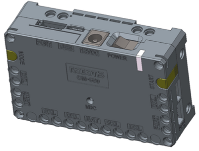
Layout
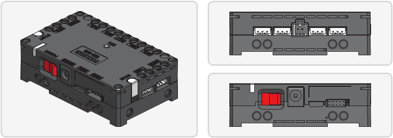
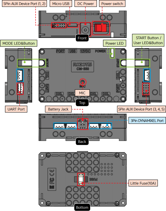
CM-550 Layout
USBMicro USB Port : The 5 pin micro USB cable can be used to connect to the USB port of the PC.UARTCommunication Port : BT-210, BT-410, LN-101, IR receiver or other communication modules can be connected.BATBattery Socket : Provided Li-Po battery can be connected.12VDCDC Input : The DC barrel jack of provided SMPS can be connected.POWERPower Switch : Controls the power supply of the controller.- Status LED : Displays voltage level and wireless device connection status with RGB LED.
MODEMODE LED : This RGB LED displays the operating mode of CM-550. Please refer to the Operating Mode of CM-550.STARTSTART LED : Please refer to the Operating Mode of CM-550.MODEMODE Button : The operating mode can be changed with this button. Please refer to the Operating Mode of CM-550.STARTSTART Button : This button runs selected operating mode. Please refer to the Operating Mode of CM-550.DXLDYNAMIXEL-X Series Port : DYNAMIXEL-X series can be connected in any of these ports.PORTROBOTIS 5 Pin Port : Sensors such as DMS, Touch sensor, IR sensor can be connected.
Servo motor, IR array sensor, Temperature & Humidity sensor can only be connected to Port 1 or 2.MICInternal Microphone : The integrated microphone detects clapping sound.FUSEFuse : 10A fuse protects electric damage.
CAUTION : The USB port on CM-550 is designed to be connected with the PC. Please do NOT connect other USB devices, or it may cause damage to the controller.
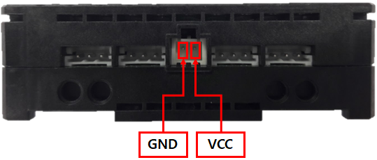
Battery Socket
The pinout of the battery socket is shown below.
ROBOTIS 5 Pin Ports
The pinout of the ROBOTIS 5 pin ports are shown below.
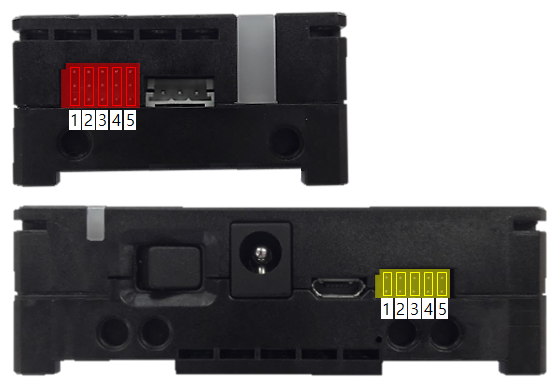
- OUT1 : 3.3 [V] Digital Output
- Port 1, 2(Yellow) maximum allowed current : < 0.5 [A]
- Port 3, 4, 5(Red) maximum allowed current : < 0.02 [A] (SM-10, IRSS-10, TMS-10 not supported)
- VCC : Power supply (5 [V])
- ADC : 3.3 [V] level Analog input
- GND : Ground (0 [V])
- OUT2 : 3.3 [V] Digital Output
- Port 1, 2(Yellow) maximum allowed current : < 0.5 [A]
- Port 3, 4, 5(Red) maximum allowed current : < 0.02 [A] (SM-10, IRSS-10, TMS-10 not supported)
Communication Port
The UART serial port supports wired or wireless communication devices. The pinout of the port is shown below.
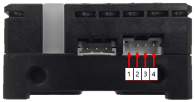
- GND : Ground (0 [V])
- VCC : Power Supply (2.7 ~ 3.6 [V])
- RXD : Receive Data
- TXD : Transmit Data
DYNAMIXEL Port
The pinout of DYNAMIXEL TTL connector is shown below.
| Item | TTL |
|---|---|
| Pinout | 1 GND2 VDD3 DATA |
| Diagram |  |
| Housing | 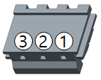 JST EHR-03 |
| PCB Header | 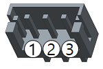 JST B3B-EH-A |
| Crimp Terminal | JST SEH-001T-P0.6 |
| Wire Gauge for DYNAMIXEL | 21 AWG |
Communication Circuit
To control the DYNAMIXEL actuators, the main controller needs to convert its UART signals to the half duplex type. The recommended circuit diagram for this is shown below.
TTL Communication
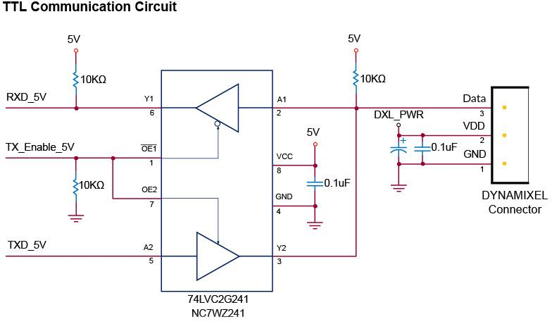
NOTE: Above circuit is designed for 5V or 5V tolerant MCU. Otherwise, use a Level Shifter to match the voltage of MCU.
- GND : Ground (0 [V])
- VDD : Power Supply (Same as Battery Level)
- DATA : Data tranceiving pin
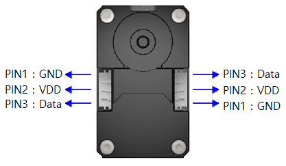
WARNING: To enhance user safety and to prevent proprietary risk or damage, be sure to check the pinout installed on DYNAMIXEL and the board. The Pinout of DYNAMIXEL may differ depending on a manufacturer of connector.
CAUTION : XL-320 is not compatible with CM-550.
Connecting Power
In order to supply power to CM-550, either connect the battery to BAT battery socket or plug the 12V SMPS DC barrel into 12VDC jack.
Set the POWER switch to ON and the Status LED will be turned on.
NOTE : If 12VDC is connected to the power source, the CM-550 controller will cut the BAT input.
How to Operate
Power Up
Setting the POWER switch to ON will turn on the CM-550 controller.
If the controller does not turn on, the battery might have been depleted. Please refer to Charging Battery section to charge the battery, or use 12V SMPS power supply to operate the robot.
Start
In order to operate the robot, press the MODE button until the button flashes green. While the MODE LED is flickering in green, press the START button to run the downloaded task code.
If the MODE LED stops flickering after pressing the START button, task is running normally.
Quit
In order to stop running the task code and exit to standby mode, press the MODE button while task is running.
Operating Mode
The MODE button flickers in Standby Mode. While the MODE LED is flickering, press the START button to enter the mode.
Press the MODE button again to exit to Standby Mode.
MANAGE
- In Manage Mode, Roboplus softwares can be connected to controllers and DYNAMIXEL’s for configuration.
- The
MODELED will appear red under Manage Mode. - R+ Manager 2.0 can be used to configure or test CM-550 and connected X series DYNAMIXEL’s.
- If CM-550 detects R+ Manager 2.0 or R+ Task 3.0 connection, the mode automatically changes to Manage Mode.
CAUTION : XL-320 is not compatible with CM-550.
PLAY
- Task code can be run in Play Mode.
- The
MODELED will appear green under Play Mode. - Task code can be downloaded to CM-550 with R+ Task 3.0.
- While the
MODELED is flickering in green, press theSTARTbutton to run the downloaded task code.
BOOT LOADER
- The firmware of CM-550 controller can be recovered under this mode.
- The
MODELED will appear blue under Boot Loader Mode. - Press and hold the
MODEbutton and turn on CM-550 or connect the USB cable to enter Boot Loader Mode. - While
MODELED is flickering in any color, press and hold theMODEbutton for five(5) seconds until the notification sounds with blueMODELED.
Firmware Recovery
In case of unexpected firmware malfunction or incomplete task code download that interferes normal operation, CM-550 can be recovered with R+ Manager 2.0 via Firmware Recovery.
It is strongly recommended to use USB port for the firmware recovery.
Compatible Software
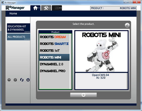
R+ Manager 2.0
RoboPlus Manager 2.0 is able to connect to CM-550 so that supported peripheral devices such as X series DYNAMIXEL, Touch Sensor, LED Module, IR Sensor and etc.
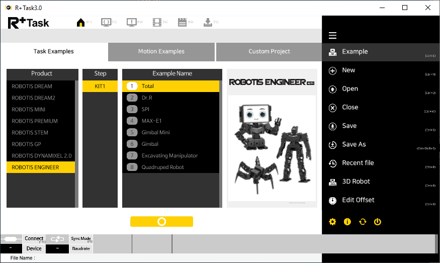
R+ Task 3.0
R+ Task 3.0 is an integrated software tool that combines R+ Task 2.0 and R+ Motion 2.0.
Task codes and Motions can be created and modified with R+ Task 3.0.
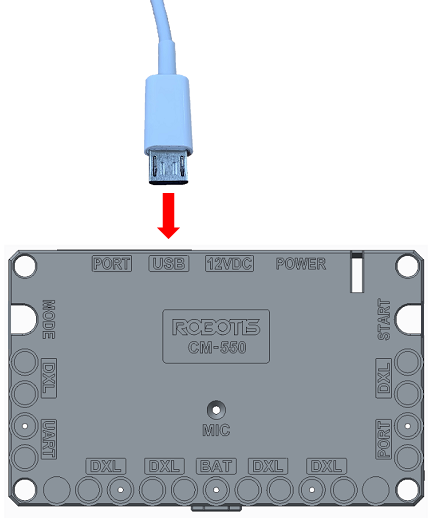
Connect to PC
There are three available options to connect PC and CM-550.
- Use 5pin micro USB cable to connect the PC and CM-550.
- Use BT-410 Dongle to pair the PC and CM-550 wirelessly.
- Use LN-101 to connect the PC and CM-550.
Connect to Smart Device
CM-550 includes BLE bluetooth slave module.
Smart devices or PC with BT-410 Dongle can be paired with CM-550 wirelessly.
-
Turn on the CM-550 controller.
-
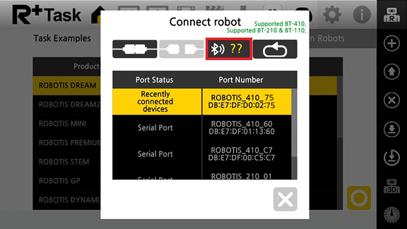
Launch the smart device app and select the bluetooth icon on the top right corner.
-
In case of R+ ENGINEER
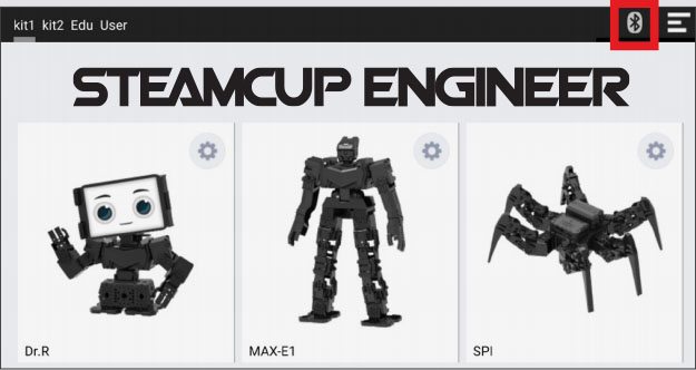
-
In case of R+ Task 3.0
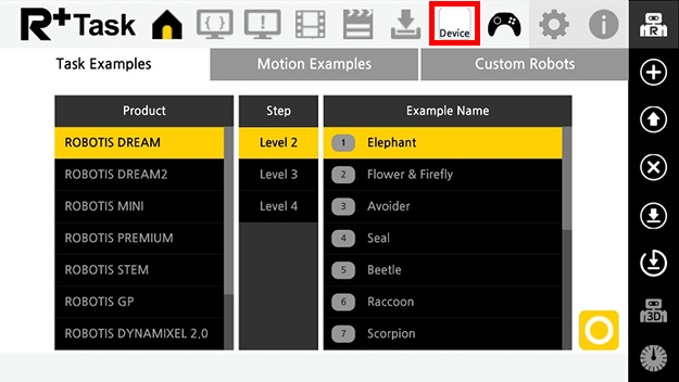
-
-
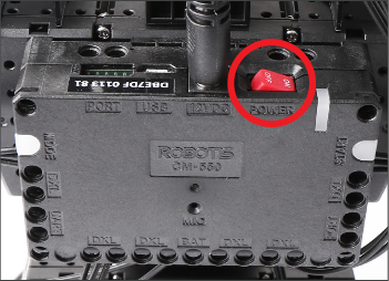
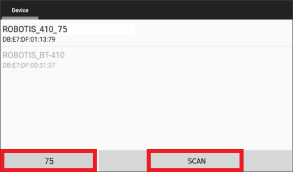
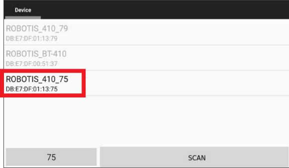
Find the address on the CM-550 controller.
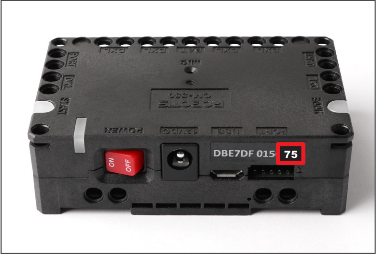
-
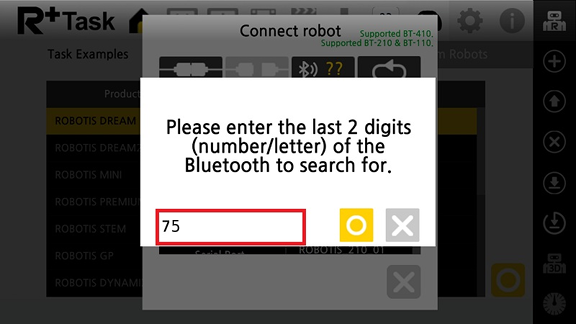
Enter the last two characters of CM-550 BLE address in the left box and press
Searchicon.-
In case of R+ ENGINEER
-
In case of R+ Task 3.0
-
-
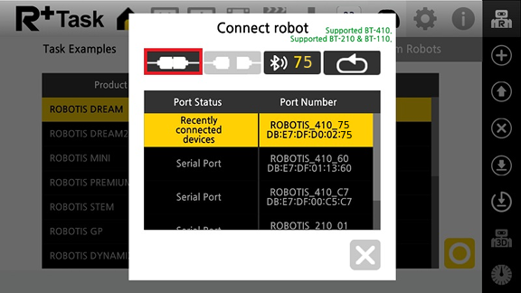
Select the CM-550 BLE address from the search list(R+ ENGINEER).
Charging Battery
CAUTION
- The provided battery must be charged with the provided charger(LBC-10) in the kit.
- Please power the charger before connecting the battery.
- Please fully charge the battery prior to first use.
-
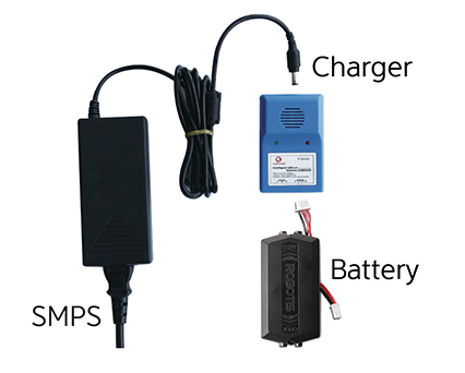
Get the rechargeable battery in the kit.
-
Connect the battery to the charger as shown below.
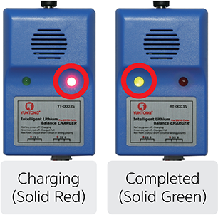
-
When fully charged, the LED will emit a solid green light.
-
The robot and controller can also be powered by the SMPS without the battery.
-
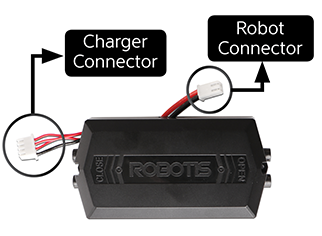
The battery has separate connectors for the charger and the robot. Please disconnect the
Robot Connectorfrom the robot when charging the battery.
Battery Level Check
Current battery life can be verified by the color of the LED located on the CM-550.
- Blue : 70% ~ 100%
- Green : 30% ~ 70%
- Red : Under 30% (Low voltage alarm)
NOTE : The Power LED will blink when Bluetooth connection is disconnected.
CAUTION : Please disconnect the battery from the charger when charging is completed. Please do not charge the battery while operating the robot.
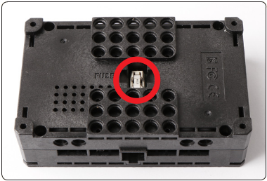
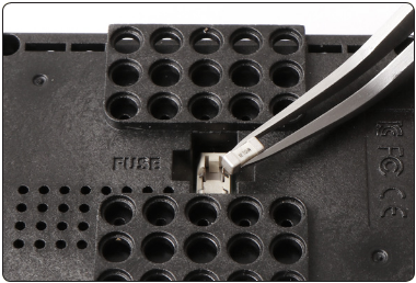
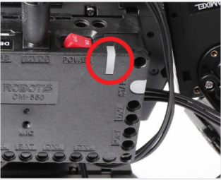
Fuse Replacement
The fuse in CM-550 protects hardware from unexpected excessive current.
If CM-550 can be turned on with the SMPS, but not with the battery, please check the fuse and replace it if necessary.
DANGER : Disconnect any power sources(SMPS, battery, USB) from CM-550 before replacing the fuse.
Disconnect power source from CM-550 and replace the fuse on the bottom of CM-550.