Integrated Sensor(AX-S1)
Introduction
CAUTION : AX-S1 is DISCONTINUED.
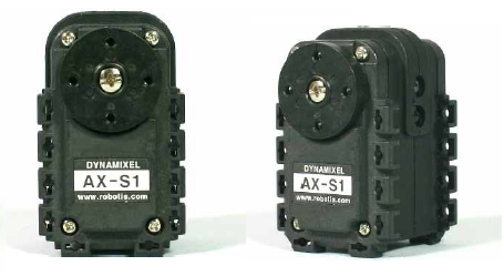
- AX-S1 is a sensor device, which plays the role of eyes and ears of robots. Distance of an object, Brightness of surroundings, heat, and sound detection functions are included; additionally, IR remote control receptor and sound-making functions are included. The configuration and the communication type of AX-S1 are equal to AX-12+’s, but it is not operated by servo motor.
Specifications
| Item | Specifications |
|---|---|
| Weight | 37g |
| Resolution | 10bit(1,024) |
| Operation Temperature | -5°C ~ +85°C |
| Voltage | 9 ~ 12V (Recommended Voltage 11.1V) |
| Maximum Current | 40mA |
| Command Signal | Digital Packet |
| Protocol Type | Half duplex Asynchronous Serial Communication (8bit,1stop,No Parity) |
| Link (Physical) | TTL Level Multi Drop (daisy chain type Connector) |
| ID | 254 ID (0~253) |
| Communication Speed | 7,843bps ~ 1 Mbps |
| Feedback | Infra-red Sensor, Internal Mic, Temperature, Input Voltage, IR Remocon Tx/Rx Data, etc. |
| Material | Engineering Plastic |
How to Communicate
The communication method and the hardware composition related to the communication of AX-S1 are the same as DYNAMIXEL AX series.
- Please refer to DYNAMIXEL Communication on the communication method and the packet composition.
- Please refer to Communication Hardware Composition of AX-Series on the communication hardware.
Control Table
Control Table consists of data regarding the current status and operation, which exists inside of DYNAMIXEL. The user can control DYNAMIXEL by changing data of Control Table via Instruction Packet.
EEPROM and RAM
Data in RAM area is reset to the initial value whenever the power is turned on while data in EEPROM area is kept once the value is set even if the power is turned off.
Address
It represents the location of data. To read from or write data to Control Table, the user should assign the correct address in the Instruction Packet.
Access
DYNAMIXEL has two kinds of data: Read-only data, which is mainly used for sensing, and Read-and-Write data, which is used for driving.
Initial Value
In case of data in the EEPROM Area, the initial values on the right side of the below Control Table are the factory default settings. In case of data in the RAM Area, the initial values on the right side of the above Control Tables are the ones when the power is turned on.
Highest/Lowest Byte
In the Control table, some data share the same name, but they are attached with (L) or (H) at the end of each name to distinguish the address. This data requires 16bit, but it is divided into 8bit each for the addresses (low) and (high). These two addresses should be written with one Instruction Packet at the same time.
EEPROM Area
| Address | Data Name | Description | Access | Initial Value |
|---|---|---|---|---|
| 0(0x00) | Model Number(L) | Lowest Byte of Model Number | R | 13(0x0D) |
| 1(0x01) | Model Number(H) | Highest Byte of Model Number | R | 0(0x00) |
| 2(0x02) | Firmware Version | Firmware Version | R | - |
| 3(0x03) | ID | DYNAMIXEL ID | RW | 100(0x64) |
| 4(0x04) | Baud Rate | Communication Speed | RW | 1(0x0x) |
| 5(0x05) | Return Delay Time | Response Delay Time | RW | 250(0xFA) |
| 16(0x10) | Status Return Level | Select Types of Status Return | RW | 2(0x02) |
RAM Area
| Address | Data Name | Description | Access | Initial Value |
|---|---|---|---|---|
| 26(0X1A) | Left Distance Data | The value of left IR Sensor | R | - |
| 27(0X1B) | Center Distance Data | The value of central IR Sensor | R | - |
| 28(0X1C) | Right Distance Data | The value of right IR Sensor | R | - |
| 29(0X1D) | Light Left Data | The value of left Light Sensor | R | - |
| 30(0X1E) | Light Center Data | The value of central Light Sensor | R | - |
| 31(0X1F) | Light Right Data | The value of right Light Sensor | R | - |
| 32(0X20) | IR Obstacle Detected | The object detected by IR | R | - |
| 33(0X21) | Light Detected | Light Detected | R | - |
| 35(0X23) | Sound Data | The value of current sound | R | - |
| 36(0X24) | Sound Data Max Hold | The value of Max Sound | RW | - |
| 37(0X25) | Sound Detected Count | The count of sound detected | RW | - |
| 38(0X26) | Sound Detected Time(L) | Lowest byte of sound detected time | RW | - |
| 39(0X27) | Sound Detected Time(H) | Highest byte of sound detected time | RW | - |
| 40(0X28) | Buzzer Data 0 | Buzzer Notes | RW | - |
| 41(0X29) | Buzzer Data 1 | Buzzer Ringing Time | RW | - |
| 44(0X2C) | Registered | Registration of Instruction | RW | 0(0X00) |
| 46(0X2E) | IR Remocon Arrived | Arrival of IR Remocon Data | R | 0(0X00) |
| 47(0X2F) | Lock | Locking EEPROM | RW | 0(0X00) |
| 48(0X30) | Remocon RX Data 0 | Lowest byte of received data packet | R | - |
| 49(0X31) | Remocon RX Data 1 | Higest byte of received data packet | R | - |
| 50(0X32) | Remocon TX Data 0 | Lowest byte of transmitted data packet | RW | - |
| 51(0X33) | Remocon TX Data 1 | Highest byte of transmitted data packet | RW | - |
| 52(0X34) | IR Obstacle Detect Compare | The reference value of object detected | RW | - |
| 53(0X35) | Light Detect Compare | The reference value of light detected | RW | - |
Control Table Description
Model Number (0)
This address stores model number of DYNAMIXEL.
Firmware Version (2)
This address stores firmware version of DYNAMIXEL.
ID (3)
The ID is a unique value in the network to identify each DYNAMIXEL with an Instruction Packet. 0~252 (0xFC) values can be used as an ID, and 254(0xFE) is occupied as a broadcast ID. The Broadcast ID(254, 0xFE) can send an Instruction Packet to all connected DYNAMIXEL simultaneously.
NOTE : Please avoid using an identical ID for multiple DYNAMIXEL. You may face communication failure or may not be able to detect DYNAMIXEL with an identical ID.
NOTE : If the Instruction Packet ID is set to the Broadcast ID(0xFE), Status Packets will not be returned for READ or WRITE Instructions regardless of the set value of Stuatus Return Level (68). For more details, please refer to the Status Packet section for DYNAMIXEL Protocol 2.0
Baud Rate (4)
Baud Rate determines serial communication speed between a controller and DYNAMIXEL.
Available value range is 0 ~ 254(0xFE), and below is the equation for BPS calculation.
Baudrate(BPS) = 2,000,000 / (Value + 1)
| Value | Baud Rate(bps) | Margin of Error |
|---|---|---|
| 1 | 1M | 0.000 [%] |
| 3 | 500,000 | 0.000 [%] |
| 4 | 400,000 | 0.000 [%] |
| 7 | 250,000 | 0.000 [%] |
| 9 | 200,000 | 0.000 [%] |
| 16 | 115200 | -2.124 [%] |
| 34(Default) | 57600 | 0.794 [%] |
| 103 | 19200 | -0.160 [%] |
| 207 | 9600 | -0.160 [%] |
NOTE : Less than 3% of the baud rate error margin will not affect to UART communication.
NOTE : For the stable communication with higher Baudrate, configure USB Latency value to the lower.
USB Latency Setting
Return Delay Time (5)
If the DYNAMIXEL receives an Instruction Packet, it will return the Status Packet after the time of the set Return Delay Time(5).
Note that the range of values is 0 to 254 (0XFE) and its unit is 2 [μsec]. For instance, if the Return Delay Time(5) is set to ‘10’, the Status Packet will be returned after 20[μsec] when the Instruction Packet is received.
| Unit | Value Range | Description |
|---|---|---|
| 2[μsec] | 0 ~ 254 | Default value ‘250’(500[μsec]) Maximum value: ‘508’[μsec] |
Status Return Level(16)
The Stuatus Return Level (68) decides how to return Status Packet when DYNAMIXEL receives an Instruction Packet.
| Value | Responding Instructions | Description |
|---|---|---|
| 0 | PING Instruction | Returns the Status Packet for PING Instruction only |
| 1 | PING Instruction READ Instruction |
Returns the Status Packet for PING and READ Instruction |
| 2 | All Instructions | Returns the Status Packet for all Instructions |
NOTE : If the Instruction Packet ID is set to the Broadcast ID(0xFE), Status Packet will not be returned for READ or WRITE Instructions regardless of Stuatus Return Level (68). For more details, please refer to the Status Packet section for DYNAMIXEL Protocol 2.0.
IR Obstacle Detect Compare Value
The reference value is set in the estimated place where an object exists on the direction of the sensor in the IR sensor value of DYNAMIXEL Sensor Module. If the sensor value is greater than the reference value, the bit which belongs to the sensor of IR Obstacle Detected (Address 0x20) is set to ‘1’ because the object is located within a certain distance; if the sensor value is less than the reference value, the bit is set to ‘0’ since the object is not located within a certain distance. IR Obstacle Detect Compare Value is assigned to two places: ROM(Address 0x14) and RAM(Address 0x34), and when the power is turned on, the value of EEPROM is copied to RAM.
Light Detect Compare Value
The reference value is set in the estimated place where a light is turned on in the light-brightness sensor of DYNAMIXEL Sensor Module. If the sensor value is grater than the reference value, the bit which belongs to Light Detected is set to ‘1’ because the light is brighter than a certain brightness; if the sensor value is less than the reference value, the bit is set to ‘0’ since the light is not brighter than a certain brightness. Light Detect Compare Value is assigned to two places: ROM(Address 0x15) and RAM(Address 0x35), and when the power is turned on, the value of EEPROM is copied to RAM.
IR Distance Sensor Value (Left/Center/Right)
It is the IR sensor value of DYNAMIXEL Sensor Module for distance measurement. If the infrared rays are emitted from the IR-emitting part of AX-S1, the emitted infrared rays are reflected after hitting walls or objects. The amount of the reflected rays is measured by the IR-receiving part of AX-S1, and the higher value is acquired, the closer walls and objects are located. The measured values have the range of 0~255; only 255 may be appeared if any object or wall is located within a certain distance. Since it is an IR-mesurement type, reflection ratio may vary depending on the color and the surface texture of walls and objects; the measured value can be different from the expected value.
Light Brightness Sensor Value (Left/Center/Right)
It is the light detection sensor value of DYNAMIXEL Sensor Module. The concept of this sensor is similar to IR sensor value’s, but it is measured without turning on the IR-emitting part; it can measure only infrared rays from a light. For that reason, the light brightness sensor value can be measured from the light which emits a lot of infrared rays such as lightbulb, and also lights from a lighter or candles can be measurede. The measured value has the range of 0~255.
IR Obstacle Detected
If IR Distance Sensor value of AX-S1 is greater than the reference value, a certain bit of object detection value is set to ‘1’, judging an object is detected. Please refer to the table below on the bits each sensor represents.
| Bit | Name |
|---|---|
| Bit 2 | Object/Light are detected by the right sensor |
| Bit 1 | Object/Light are detected by the central sensor |
| Bit 0 | Object/Light are detected by the left sensor |
Light Detected
If light brightness sensor value of AX-S1 is greater than the reference value, a certain bit of light detected value is set to ‘1’, judging a light is detected. The bit each sensor represents is equal to the object detection value. (See Address 0x20 above)
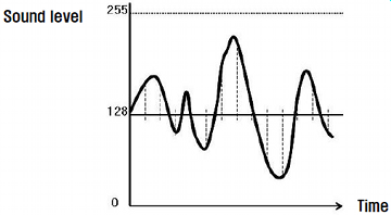
Sound Level
The level of the sound which is coming into the mic of AX-S1 is measured and converted into numerical value. Because the sound level is fulctuated up and down as below, if there is no sound, the numerical value of 127~128 (0x7F~0x80) is got, and it gets closer to 0 or 255 (0xFF) as the sound gets louder. The sound level is entered about 3800 times per second.
Maximum Sound Level
The loudest sound level is saved separately among the sound levels of AX-S1. That is, if current sound level is louder than the saved maximum sound level, the current sound is copied as maximum sound level. Therefore, the sound level lower than 128 is actually ignored, and it is assumed that the loudest sound level at the moment is accumulated and saved. See the following picutre for better understanding.
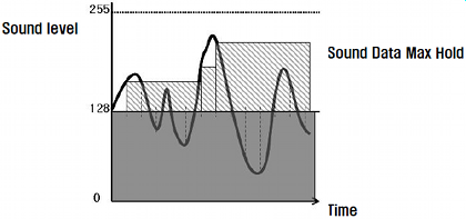
Be careful if the maximum sound leve becomes 255 (0xFF) while being accumulated, the maximum sound level remains 255 because it cannot exceed 255. Therefore, ‘0’ must be written on the maximum sound level part to measure the maximum sound level.
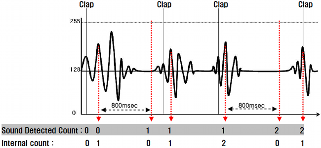
Sound Detected Count
AX-S1 has a function to count 1 time if a certain level of sound is made. For instance, it is possible to count the number of claps. However, to prevent 1 clap from being counted as multiple claps, once claps are counted one time, the claps are not counted for 80msec. After the last count, the counted value is saved as sound detected count in 800msec. To recognize the time when the sound detected count is increased, count the number internally, and then save the value in the sound detected count in 800msec while initializing the internal count as ‘0.’ See the following picture for better understanding.
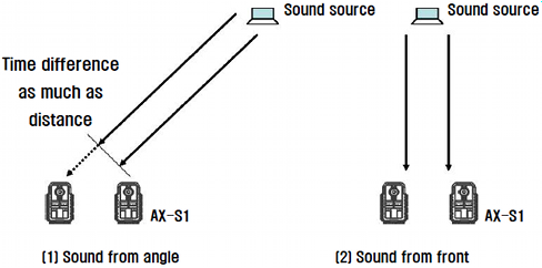
Sound Detected Time
AX-S1 has a function to save the time of the moment whenever sound detected count is done. The function is provided to detect the direction of sounds, and at least 2 units of AX-S1 are necessary. The function is based on the difference of sound-incoming time to each of AX-S1 Mics using the speed of sound (The speed of sound is about 343m/sec ot 20 degrees of Celsius). Sound detected time is counted internally (Repeating the count of 0~65535), and the currently counted value is saved when sound detected count is increased. Thus, after initializing sound detected time simultaneously to ‘0’ using Broadcasting command by separating 2 units of AX-S1 properly from each other, if sounds are made, the time difference between the two AX-S1s occurs pursuant to the directions of sounds. If the sound source is in the front, the sound is detected almost at the same time, but if the sound source is not in the front, the time difference occurs pursuant to the apart distance of AX-S1. The direction of sound sources can be roughly estimated using the principle above. See the following picture for better understanding.
The sound counted time of AX-S1 is counted about every 4.096 msec and it is counted again from ‘0.’ Therefore, calculating by the speed of sound, the sound moves about 0.02mm per count, and the distance between two AX-S1s must be within 70cm. For example, if the two AX-S1s are 10cm apart, in case of using the method above, the difference of sound detected time between two AX-S1s may vary up to 5000. (If the difference is about 5000, it means the sound source is located at 90 degrees left or right of the two AX-S1s)
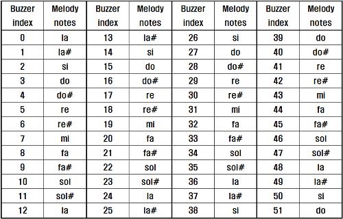
Buzzer Notes
A buzzer is installed in AX-S1, and simple beep sounds can be made. Total 52 musical notes can be made in Buzzer Notes, and various notes can be made because there are whole tones and halftones in each octave. The values of Buzzer Notes are assigned as the table below.
Buzzer Ringing Time
AX-S1 has a function to control the buzzer alarcming time. It is possible to control by the unit of 0.1 second, and the minimum length is set to 0.3 seconds; the time can be extended up to maximum 5 seconds. That is, if 0~3 is entered, the buzzer rings for 0.3 seconds; if the value over 50 is entered, the buzzer rings only for 5 seconds regardless of the value. Moreover, if the ringing is finished, the buzzer ringing time is automatically initialized to ‘0.’ There are 2 special buzzer ringing time functions for AX-S1. Firstly, the buzzer can be ringing without stopping. If 254 is entered in buzzer ringing time, and the number of desired musical notes is entered, the buzzer rings without stopping. To stop the ringing, ‘0’ is entered in buzzer ringing time. Secondly, the buzzer can play special melodies. If 255 is entered in buzzer ringing time, and then the value 0~26 is entered in buzzer notes, 27 melodies corresponding to each number can be played. If the ringing is finished, the buzzer ringing time is automatically initialized to ‘0.’
Registered Instruction
| Value | Meaning |
|---|---|
| 0 | There are no commands transmitted by REG_WRITE |
| 1 | There are commands transmitted by REG_WRITE. |
NOTE : If ACTION command is executed, the value is changed into 0.
Arrival of New Remocon Data
IR remote controller communication is possible among other AX-S1s since IR remote controller sensor is installed on the front of AX-S1. The data can be transmitted by 2 byte unit. IR remocon data can be transmitted to any direction since IR-emitting parts are installed in 3 directions: front/left/right, but the IR remocon data can be received only in limited angle because IR remocon sensor is installed only on the front. If IR remocon data is received on the sensor, the new remocon data arrival value is changed into ‘2’; it means 2 byte is received. If the received remocon data are read, it is automatically initialized to ‘0.’
Lock
| Value | Meaning |
|---|---|
| 0 | EEPROM area can be modified. |
| 1 | EEPROM area cannot be modified. |
CAUTION : If Lock is set to 1, the power must be turned off and then turned on again to change into 0.
Received Remocon Data
The received data is saved in IR remocon sensor. If this value is read, the new remocon data arrival value is automatically initialized to ‘0.’
Remocon Data To Be Transmitted
The remocon data to be transmitted through the IR-emitting part is written. The remocon data is transmitted as soon as the value of 2 bytes is written.
IR Obstacle Detect Compare Value
IR Obstacle Detect Compare Value of Address 0x14 is saved in RAM area of Control Table. Currently, it is not possible to detect normally in short distance(e.g. within 5cm distance, the maximum value is always acquired) since, in case of IR Sensor of AX-S1, infrared rays are emitted strongly to detect in long distance. Therefore, AX-S1 supports low-sensitive mode for acurate detection in short distance; if ‘0’ is entered in IR Obstacle Detect Compare Value, it is converted to low-sensitive mode. In low-sensitive mode, the long distance sensor performance is not satisfactory, but accurate and sensitive detection is possible in short distance because it is not saturated to the maximum value.
Light Detect Compare Value
Light Detect Compare Value of Address 0x15 is saved in RAM Area of Control Table.
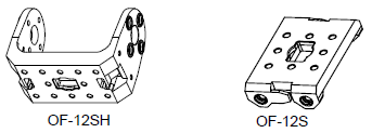
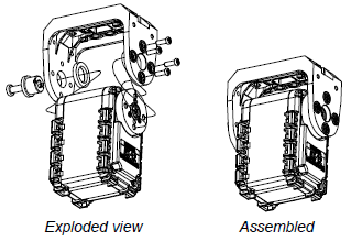
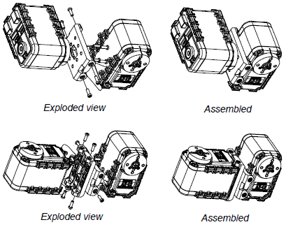
How to Assemble
The types of AX-S1 option frames are as follows. The frame of AX-S1 is compatible with the frame of AX-12/12+.
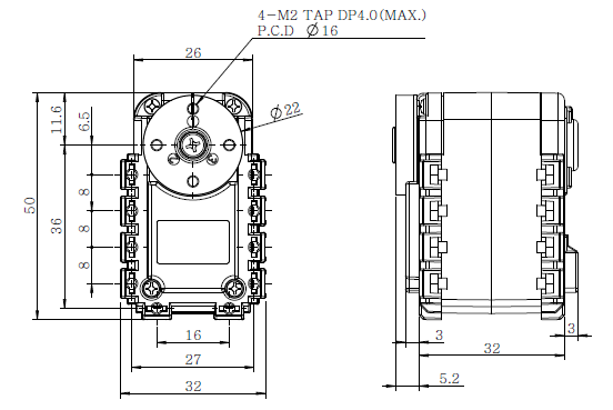
References
Drawings