
Introduction
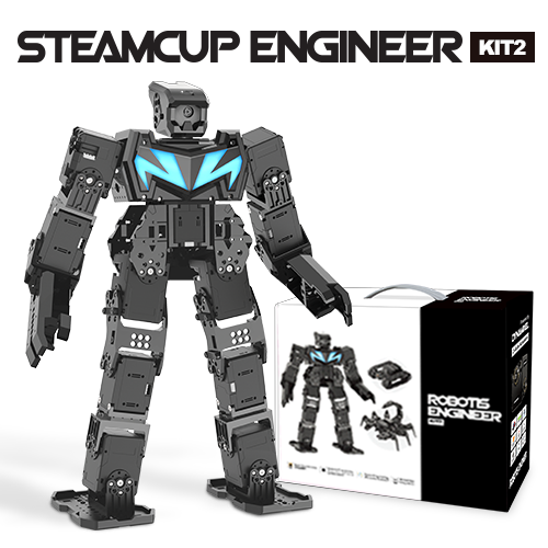
ROBOTIS ENGINEER is the next generation robot that adopts AI technology based on smart devices.
- Provides standardized curriculum for multi level robotics educational courses.
- Joint structure allows diverse motions for versatile robots.
- Supports 3D part designing and printing.
- Provides an exclusive app (R+ ENGINEER) and software (R+ Task 3.0).
- Supports Raspberry Pi and Camera.
- Kit includes parts to build 3 expansion robot figures (
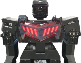
MAX-E2,Commando,Scorpi). Build up to 5 example figures total with Advanced Study Materials.
CAUTION ENGINEER KIT 2 is an expansion for ENGINEER KIT 1. Parts from ENGINEER Kit 1 are required to build the figures in ENGINEER KIT 2.
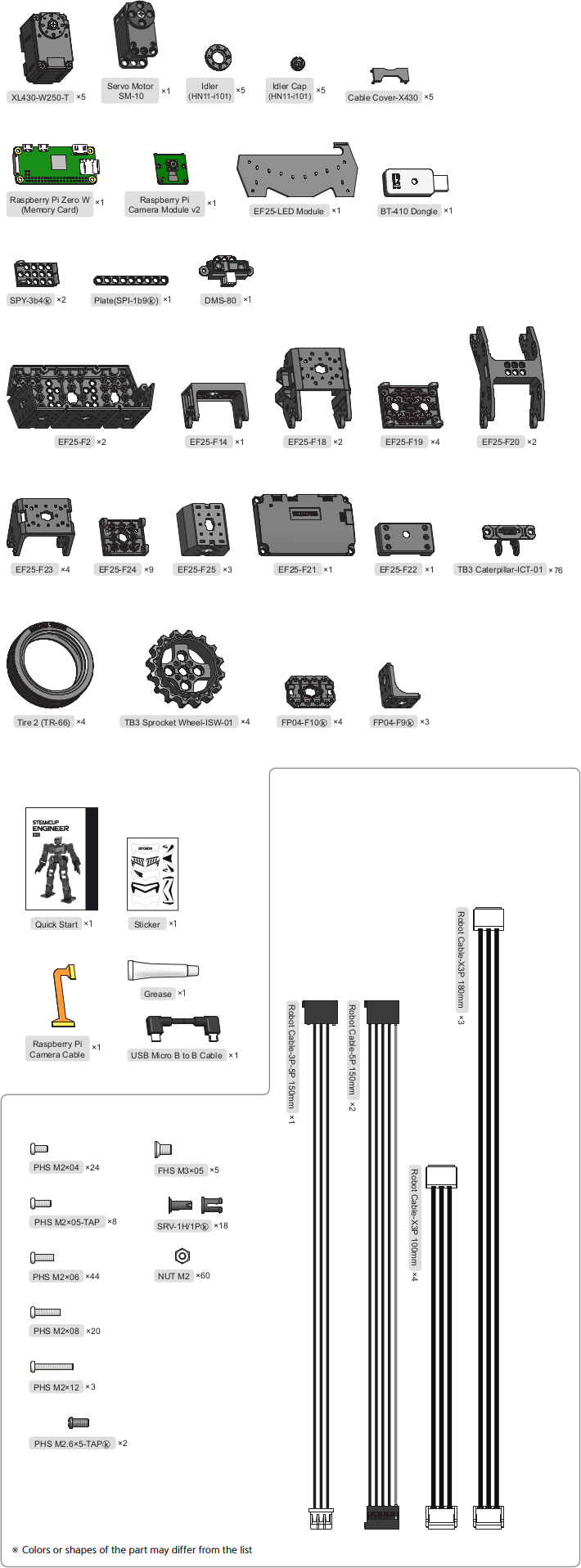
Parts List
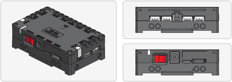
CM-550 Controller
Specifications
| Item | Specifications |
|---|---|
| Weight | 58.8 [g] |
| MCU | ARM Cortex-M4 (168 [MHz], 32 [Bit]) |
| Operating Voltage | Battery : 6.5 ~ 15 [V], Recommended 11.1 [V] (Li-PO 3cell) SMPS : 6.5 ~ 15 [V], Recommended 12.0 [V] Micro USB : 4.75 ~ 5.25 [V], Recommended 5.0 [V] |
| Current Consumption | Standby : 50 [mA] Port 1 ~ 2 I/O Max : 0.5 [A] Port 3 ~ 5 I/O Max : 0.02 [A] Total : 10 [A] (Fuse) |
| Operating Temperature | -5 ~ 70 [°C] |
| Communication Module | BLE Slave Module |
| Internal I/O Devices | Buttons : 2 (MODE, START) Mic (Sound Detection) : 1 Buzzer : 1 Voltage Sensor : 1 Gyro Accelerometer : 1 Temperature Sensor : 1 RGB LED : 3 |
| External I/O Devices | ROBOTIS 5 Pin Port : 5 (SM-10 / IR Array / TMS-10 : Use Port 1 or 2) X series DYNAMIXEL Ports : 6 |
CM-550 Layout
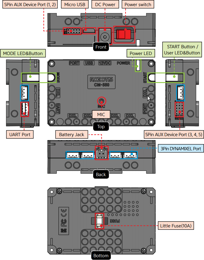
USBMicro USB Port : The 5 pin micro USB cable can be used to connect to the USB port of the PC.UARTCommunication Port : BT-210, BT-410, LN-101, IR receiver or other communication modules can be connected.BATBattery Socket : Provided Li-Po battery can be connected.12VDCDC Input : The DC barrel jack of provided SMPS can be connected.POWERPower Switch : Controls the power supply of the controller.- Status LED : Displays voltage level and wireless device connection status with RGB LED.
MODEMODE LED : This RGB LED displays the operating mode of CM-550. Please refer to the Operating Mode of CM-550.STARTSTART LED : Please refer to the Operating Mode of CM-550.MODEMODE Button : The operating mode can be changed with this button. Please refer to the Operating Mode of CM-550.STARTSTART Button : This button runs selected operating mode. Please refer to the Operating Mode of CM-550.DXLDYNAMIXEL-X Series Port : DYNAMIXEL-X series can be connected in any of these ports.PORTROBOTIS 5 Pin Port : Sensors such as DMS, Touch sensor, IR sensor can be connected.
Servo motor, IR array sensor, Temperature & Humidity sensor can only be connected to Port 1 or 2.MICInternal Microphone : The integrated microphone detects clapping sound.FUSEFuse : 10A fuse protects electric damage.
CAUTION : The USB port on CM-550 is designed to be connected with the PC. Please do NOT connect other USB devices, or it may cause damage to the controller.
Raspberry Pi
Raspberry Pi is a single board computer based on the Linux operating system developed by the Raspberry Pi Foundation in the UK for educational purposes.
Raspberry Pi Zero W
The Raspberry Pi Zero is a compact computer that’s smaller in size and lower in price while retaining the functionality of a traditional Raspberry Pi.
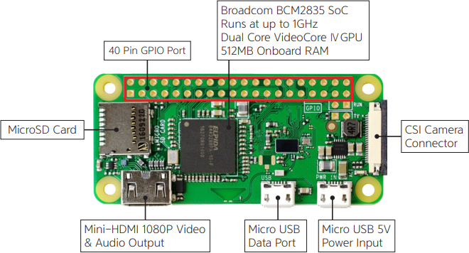
Raspberry Pi Zero W Features
40 Pin GPIO Port: General Purpose Input/Output pins on the Raspberry Pi.Broadcom BCM2835: The Broadcom processor used in Raspberry Pi ZeroCSI Camera Connector: Connector for the Raspberry Pi camera module.Micro USB 5V Power Input: 5 V Power Input via Micro USB cable.Micro USB Data Port: Port for a peripheral device (Mouse or Keyboard) using USB HUB.Mini-HDMI 1080P Video & Audio Output: Mini-HDMI port is used to output a monitor & audio.MicroSD Card: MicroSD card slot is used to install a provided image file in.
Raspberry Pi Camera Module
Raspberry Pi Camera can be connected with Raspberry Pi and can perform various functions as face and color recognition, line detection, and video streaming.
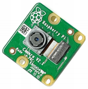
Raspberry Pi Camera Module
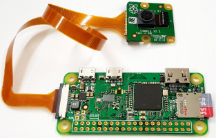
Raspberry Pi Zero W with the Camera Module.
How Raspberry Pi Zero can be connected to CM-550 controller?
NOTE: After turning on the controller, wait for 70 seconds to boot Raspberry Pi. Once booting is completed, the yellow LED will light on with beep sound.
DYNAMIXEL
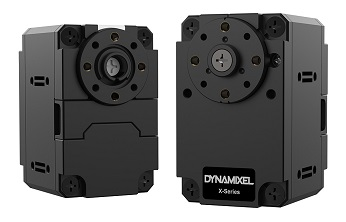
XL430-W250-T
The DYNAMIXEL XL430-W250-T is a smart actuator designed for robot applications. The XL430-W250-T offers various control modes such as speed, position, extended position(multi-turn) and PWM and is capable of generating 1.4 N.m torque at 11.0 V.
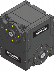
2XL430-W250
2XL430-W250 is a ground breaking DYNAMIXEL that allows to control 2 axis(2 DOF) with a single module. In order to control 2 axis at the same time, each axle is assigned with different ID while sharing an identical Baudrate. Since the Control Table for each axle is separated except the Baudrate, 2XL can be applied in various applications.
The usage is identical to other DYNAMIXEL’s, but be aware that Firmware Recovery will reset both axis to factory settings.
LED Module
The R / B LED board, which can control colors (red, blue and violet) and light intensity, can be attached to the robot’s appearance to give a colorful LED effect or to distinguish teams by LED color in competitions.
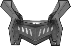
LED Module
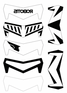
Stickers for LED Module
LED Module Equipped for MAX-E2
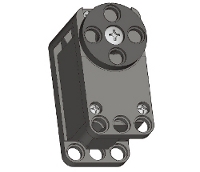
Servo Motor
An Actuator is often used for motion control in applications which require an apparatus to rotate at a certain angle or to move at a specific position. DYNAMIXEL can offer various operating modes, of which the wheel based rotational movement as well as precise position for joint movement are the most popular.
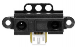
DMS-80
DMS-80(Distance Measuring Sensor) is a sensor to detect the distance using infrared sensor. Different to the common infrared sensor, the DMS sensor is rarely affected by the color of the refelctor and detection distance can be extended up to 10 to 80 cm.
Cautions
Safety Precautions
![]()
- Read this manual carefully before getting started.
- Only use provided tools in the kit.
- Keep the robot away from the face and body when the robot is operating.
- Be careful for getting fingers or part of the body stuck in the robot joints.
- Do not operate or store the robot under the direct sunlight.
- Do not operate or store the robot near water or heat source.
- Do not tamper or disassemble components.
- Keep the robot and parts away from infants or younger children.
- Do not impact or poke the robot with sharp objects.
Precautions on Use
- Use provided screwdriver(PH 1) in the kit for tightening screws.
- Do not apply excessive force on screws and parts when assembling.
- Operate the robot on the floor to avoid any damages from falling.
- Accidental damages from falling is not covered by warranty.
- DYNAMIXEL internal gears and robot joints are expendables. Excessive use or long term use may develop the backlash.
- The robot in a rapid motion (i.e, a combat motion) consumes a lot of current momentarily and may cause the unexpected Power off due to the lack of provided power from its power source. In this case, please use a battery or SMPS with an high ampere (A) to prevent from the unexpected power off.
Precautions on Battery
![]()
- The battery must be disconnected from the robot when not used or charged with the designated charger.
- Do not disassemble or impact the battery or charger.
- Do not heat the battery and avoid contact with fire and liquids.
- Do not place battery in the microwave, laundry machine, refrigerator, or dryer.
- Do not use damaged batteries (deformed, swollen, external damages).
- Do not short the battery.
- Do not reverse the polarity of the battery when charging.
- Do not charge the battery when it is hot. Let the battery cools down to the room temperature before charging
- Do not store the battery in hot or humid place.
- Do not charge multiple batteries with the charger at the same time.
- Do not connect the battery to the charger when the charger is not connected to the power source.
Assembly Precautions
DYNAMIXEL Assembly
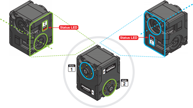
- In order to control 2 axis at the same time, each axle is assigned with different ID while sharing an identical Baudrate.
- The ID and Status LED is located on the opposite side of the output horn.
- ROBOTIS ENGINEER uses bolts to securely assemble the robot joints (Below image shows where bolts are required to attach the frame on DYNAMIXEL).
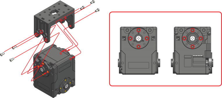
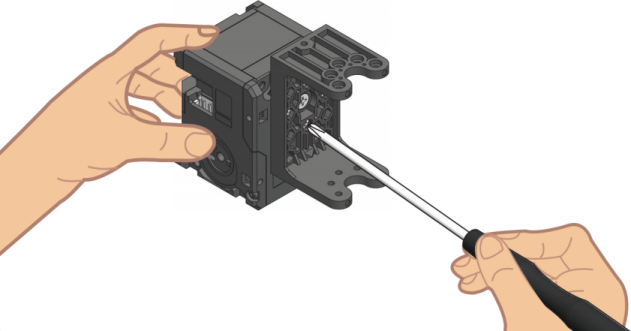
CAUTION : Please use the designated screw driver(PH 1) when assembling bolts.
Check DYNAMIXEL ID
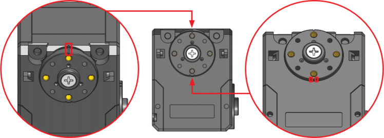
Check DYNAMIXEL Horn Position
CAUTION
- The marking on the housing should match to the horn marking when properly centered.
- In order to align the horn to the center, use PH 1 screw driver to rotate the horn screw to clockwise. Be aware of rotating the screw to counter clockwise as it will release the screw.
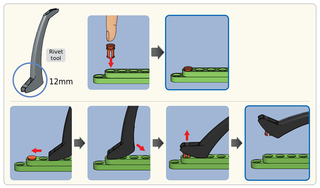
Rivet Assembly
6mm Rivet
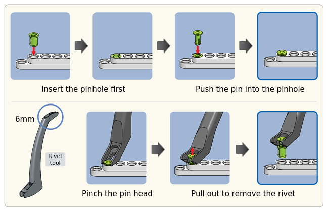
CAUTION : When reusing rivets, the pin hole must be inserted first. Used rivet will not be separated into pin and pinhole.
12mm Rivet
Cable Assemlby
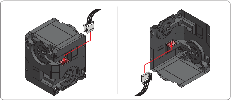
Connector
Both connectors are linked to supply power and communication to the module. Please use any connector for easier assembly.
Wiring through Idler Cap
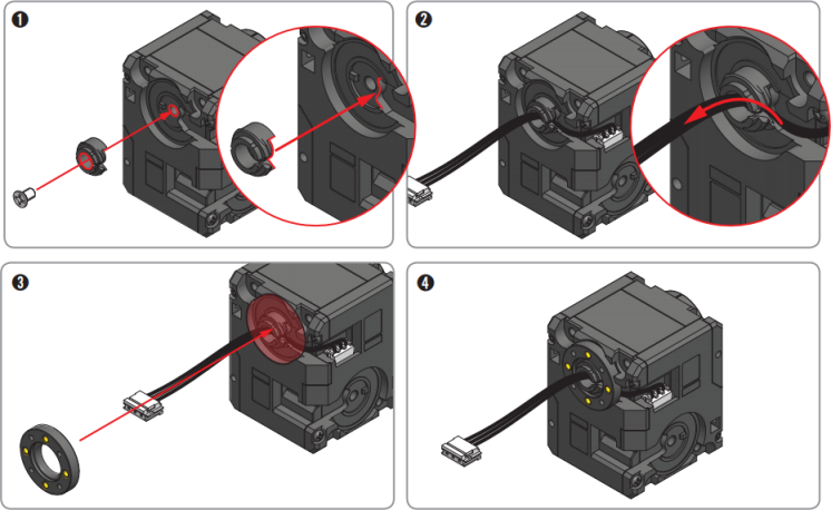
NOTE :
Through hole wiring method helps to increase the durability of cable and to simplify cable assembly.
It is not a mandatory and it may require more time to replace the cable afterward.