
CM-50 Controller
Introduction
- CM-50 controls PLAY 700 and OLLOBOT.
- CM-50 is compatible to 12mm hole pitch ROBOTIS blocks.
- IR sensors and geared motors are implemented in the controller.
- Write a program and control the robot with RoboPlus Task 2.0, R+Block
- RoboPlus Motion does NOT support CM-50.
Specifications
| Item | Description |
|---|---|
| Weight | 165g |
| CPU | STM32L151C8 |
| Size | 120 mm x 61 mm x 36 mm |
| Voltage Supply | 3.2V ~ 4.8V (3 x AA Batteries) |
| Internal I/O components | IR sensor(measure distance) x 3 Mic(Sound sensor) x 1 Buzzer x 1 LED x 3 (Power, Red, Blue) |
| External I/O components | 4-pin communication (wireless control & download) x 1 |
![]()
DANGER
(Ignoring these warnings may cause serious injury or death)
- Never place items containing water, flammables/open flames, or solvents near the product.
- Never place fingers, arms, toes, and other body parts near product during operation.
- Cease operation and remove power from the product if the product begins to emit strange odors, noises, or smoke.
- Keep product out of reach of children.
- Check input polarity before installing or energizing wiring or cables.
![]()
CAUTION
(Ignoring these warnings may cause mild injury or damage to the product)
- Always comply with the product’s offical operating environment specifications including input voltage, current, and operating temperature.
- Do not insert blades or other sharp objects during product operation.
![]()
ATTENTION
(Ignoring these warnings may cause minor injury or damage to the product)
- Do not disassemble or modify the product.
- Do not drop the product or apply strong impacts.
- Do not connect or disconnect DYNAMIXEL cables while power is being supplied.
Control Table
Control Table consists of data regarding the current status and operation of controller. The user can control controller by changing data of Control Table via Instruction packet.
EEPROM and RAM
Data in RAM area is reset to initial values whenever the power is turned on while data in EEPROM area is kept once values are set even if the power is turned off.
Address
Represents the location of data. To read from or write data to the control table the user should assign the correct address in the Instruction packet.
Access
Controller has two kinds of data: Read-only data, used mainly for sensing, and read-and-write data used for driving.
Initial Value
In case of data in the EEPROM Area, the initial values on the right side of the below Control Table are the factory default settings.
In case of data in the RAM Area, the initial values on the right side of the following control table are the ones when the power is turned on.
Size
The Size of data varies from 1 ~ 4 bytes depend on their usage. Please check the size of data when updating the data with an Instruction Packet.
EEPROM Area
| Address | Size[byte] | Data Name | Access | Init Value |
|---|---|---|---|---|
| 0 | 2 | Model Number | R | 410 |
| 6 | 1 | Firmware Version | R | - |
| 7 | 1 | ID | RW | 200 |
| 8 | 1 | Baud Rate (UART) | R | 1 |
| 9 | 1 | Return Delay Time | RW | 0 |
| 10 | 1 | Status Return Level | RW | 2 |
RAM Area
| Address | Size[byte] | Name | Description | Access | Init Value |
|---|---|---|---|---|---|
| 21 | 1 | Mode Number | Operation Mode | RW | - |
| 25 | 1 | Press Counter | Start Button Click Counts | R | - |
| 30 | 2 | My Zigbee ID | Local Zigbee ID | R | - |
| 32 | 2 | Your Zigbee ID | Remote Zigbee ID | RW | - |
| 36 | 1 | IR Communication Channel | IR Receiver Channel Number | RW | 1 |
| 73 | 1 | 128ms Timer Value | 128ms Timer Counter | RW | 0 |
| 74 | 2 | 1ms Timer Value | 1ms Timer Counter | RW | 0 |
| 76 | 1 | Power Save Timer Value | Power Save Timer Counter | RW | 0 |
| 77 | 1 | Random Number | Creating Random Number | RW | - |
| 79 | 1 | RED LED | RED LED Status | RW | 0 |
| 80 | 1 | BLUE LED | BLUE LED Status | RW | 0 |
| 84 | 1 | Buzzer Index | Buzzer Melody Frequency | RW | 0 |
| 85 | 1 | Buzzer Time | Buzzer Play Period | RW | 0 |
| 86 | 1 | Sound Detected Count | Final Count for Detected Sound | R | 0 |
| 87 | 1 | Sound Detecting Count | Current Count for Detected Sound | R | 0 |
| 88 | 1 | Low Battery Warning | Enable/Disable Low Battery Warning | RW | 0 |
| 91 | 2 | Internal Right IR Sensor Value | Sensor Value of Right IR | R | - |
| 93 | 2 | Internal Left IR Sensor Value | Sensor Value of Left IR | R | - |
| 95 | 2 | Internal Center IR Sensor Value | Sensor Value of Center IR | R | - |
| 97 | 1 | Input Voltage | Present Input Voltage | R | - |
| 136 | 2 | Port 1 Motor Speed | Speed of the Motor on Port 1 | RW | 0 |
| 138 | 2 | Port 2 Motor Speed | Speed of the Motor on Port 2 | RW | 0 |
NOTE : Control Table can be tested with R+ Manager 2.0.
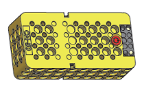
Layout
- Start button: Click the Start button to turn on the controller and run downloaded program. Power LED will be turned on.
- IR sensors : 3 IR sensor measurements can be used to program the robot.
- 4-pin communication port : Located next to the battery socket. ZIG-110A, BT-210, BT-410 can be connected.
Connecting Power
- CM-50 requires three(3) AA batteries to operate.
How to Operate
- Press the
Start Buttonto turn on the controller and run the downloaded program. - Press the
Start Buttonmultiple times to turn on the controller with a selected example. - Press and hold the
Start Buttonto change the operation mode.- Hold the
Start Buttonfor longer than 1 second until 2 beeps. LED turns on, and the controller enters to manage mode (Downloaded task will not run in this mode). - Hold the
Start Buttonfor longer than 5 seconds until 3 beeps. The controller is entered to firmware recovery mode.
- Hold the
- To turn off the controller press the
Start Buttonagain.
Connect to PC
- To connect the CM-50 to the PC, BT-210 or BT-410 or LN-101 is required.
- BT-210 can be used for the PC that supports Bluetooth.
- BT-410 requires BT-410 Dongle in order to connect to PC.
Wireless Communication
The CM-50 is compatible with ZIG-110, BT-110, BT-210, BT-410 wireless communications modules.
Mode Select
Play Mode
- Play Mode runs downloaded task.
- Press the
Start Buttononce to start the controller with Play Mode.
Manage Mode
- Manage Mode is used when recovering or updating controller firmware, and selecting RC-200 remote controller channel.
- Press and hold the
Start Buttonuntil 2 beeps, then release the button to start the controller with Manage Mode.
Tuning Mode
- Each motor can be tuned for the straight forware / backward movements.
- Two methods are available to start the Tuning mode.
First Method
- Place a white paper in front of the left and right IR sensor of CM-50.
- Press and hold the
Start Buttonuntil two(2) beeps, then release the button. - A melody will be played if the controller is entered to the Tuning Mode.
NOTE : If a melody is not played after the two beeps, the CM-50 controller is started with Manage Mode.
Please turn off the controller and try again.
WARNING : Please disconnect BT-210 or BT-410 modules from CM-50. Tuning Mode cannot be started when bluetooth modules are connected.
Second Method
- Turn on the CM-50 controller.
- Press and hold the
Start Buttonuntil three(3) beeps, then release the button. - A melody will be played if the controller is entered to the Tuning Mode.
WARNING : Please hold down the Start Button firmly until to hear three beeps or else the controller could be turned off.
Straightness Tuning
If the robot dosen’t move straight and keep steering to the right or left, the straightness can be tuned under Tuning Mode.
In order to synchronize right and left wheel speed, you need to tune the motor with a remote controller(RC-100B, RC-200, Smart Device).
NOTE : Tuning Mode for CM-50 is supported from the Firmware version 77 or above.
RC-100B
- Prepare a pair of BT-210 or BT-410 (Master/Slave module).
- Start the CM-50 controller with Tuning Mode.
- Connect the BT-210 or BT-410 Slave module to CM-50 controller.
- Connect the BT-210 or BT-410 Master module to RC-100B remote controller.
- Follow the Tuning Guide to tune the motor speed, then save the configuration.
RC-200
RC-200 supports IR communication with controller. In order to use RC-200 for the tuning, IR communication channel has to be configured before tuning the motor.
- Start the CM-50 controller with Manage Mode.
- Press and hold down
Vand↲button for 5 seconds until2,4,7,8,9buttons on RC-200 light up. - Select the channel to use(1 ~ 25), then enter the channel number from RC-200.
- Press the
↲button to save the channel setting. - Three beeps will sound consecutively if RC-200 is succesfully connected to the controller.
- Start the CM-50 controller with Tuning Mode.
- Follow the Tuning Guide to tune the motor speed, then save the configuration.
NOTE : Please point the RC-200 to IR receiver of the controller for the best signal reception.
Smart Device
Smart devices with R+ m.Task 2.0 app can be used as a remote controller instead of RC-100B or RC-200.
- Install R+ m.Task 2.0 on the smart device.
- Start the CM-50 controller with Tuning Mode.
- Connect the BT-210 or BT-410 Slave module to CM-50 controller.
- Run R+ m.Task 2.0 then use Remote Controller Program to connect the CM-50 controller.
- Follow the Tuning Guide to tune the motor speed, then save the configuration.
CAUTION : BT-210 and BT-110 do not support iOS smart devices.
Tuning Guide
NOTE
- After entering the Tuning Mode, push the button
4on the remote controller to activate the wheel. - Integrated motors will be rotating at a maximum speed under the Tuning Mode.
- Repeat the tuning to enhance the straightness.
L Button : Steer to the left.
R Button : Steer to the right.
1 Button : Switch the forward / reverse directions.
WARNING : It is recommended to tune for forward / reverse directions by pressing button 1.
2 + L Button : Fine steer tune to the left.
2 + R Button : FIne steer tune to the right.
Start Button : Save the setting and exit.