
NOTE: The OpenCM 9.04 e-Manual in Japanese (日本語) is available for the Japanese.
Introduction
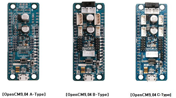
OpenCM 9.04
- OpenCM9.04 Types Package
| Item | OpenCM9.04 A Type | OpenCM9.04 B Type | OpenCM9.04 C Type |
|---|---|---|---|
| Power Switch | X | 1 | 1 |
| User Button | 1 | 1 | 1 |
| 2Pin Battery(LBS-40) | X | 2 | 2 |
| JTAG/SWD | X | 1 | 1 |
| Micro B USB | X | 1 | 1 |
| 5-Pin Port | X | 4 | 4 |
| DYNAMIXEL TTL BUS | X | 4 1 |
4 2 |
| 4 Pin Communication | X | 1 | 1 |
1: MOLEX 53253-0370 x 2(for XL-320), MOLEX 22-03-5035 x 2(for AX/MX-Series)
2: MOLEX 53253-0370 x 4(for XL-320)
- OpenCM9.04 is a microcontroller board based on 32bit ARM Cortex-M3. The OpenCM9.04’s schematics and source codes are open-source.
- 3 types are available: Type A & Type B & Type C. The difference between Type A,Type B, Type C is the availability of the connectors. (Refer to the image and table above.)
(OpenCM9.04 Accessory Set can be purchased to acquire all the necessary connector to upgrade Type A to Type B Type C.) OpenCM9.04 Accessory Set
NOTE : Refer to the ROBOTIS-MINI for controller recovery (type C-only) ROBOTIS-MINI Controller Firmware Update
CAUTION : Please DISCONNECT OpenCM9.04 and OpenCM 485 Expansion board when updating or recovering DYNAMIXEL firmware.
Specifications
| Item | Description |
|---|---|
| CPU | STM32F103CB (ARM Cortex-M3) |
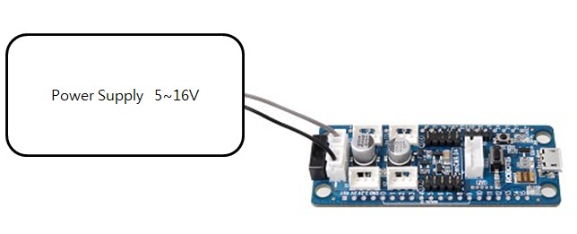
| Operation Voltage | 5V ~ 16V |
| I/O | GPIO x 26 |
| Timer | 4 (16bit) |
| Analog Input(ADC) | 10 (12bit) |
| Flash | 128Kb |
| SRAM | 20Kb |
| Clock | 72Mhz |
| USB | 1 (2.0 Full Speed) Micro B Type |
| USART | 3 |
| SPI | 2 |
| I2C(TWI) | 2 |
| Debug | JTAG & SWD |
| DYNAMIXEL TTL BUS | 4 (Max 1Mbps) |
| Dimensions | 27mm x 66.5mm |
- USB power is cannot be used to operate DYNAMIXEL’s. Separate power supply needs to be provided.
(OpenCM9.04 can operate using power supplied via USB, battery, + - terminal.) - Check the operating voltage for peripheral devices when using power supply. DYNAMIXEL or XL-series receives the exact same voltage.
- XL-320 cannot be used with other DYNAMIXEL’s due to the difference in operating voltages.
![]()
DANGER
(Ignoring these warnings may cause serious injury or death)
- Never place items containing water, flammables/open flames, or solvents near the product.
- Never place fingers, arms, toes, and other body parts near product during operation.
- Cease operation and remove power from the product if the product begins to emit strange odors, noises, or smoke.
- Keep product out of reach of children.
- Check input polarity before installing or energizing wiring or cables.
![]()
CAUTION
(Ignoring these warnings may cause mild injury or damage to the product)
- Always comply with the product’s offical operating environment specifications including input voltage, current, and operating temperature.
- Do not insert blades or other sharp objects during product operation.
![]()
ATTENTION
(Ignoring these warnings may cause minor injury or damage to the product)
- Do not disassemble or modify the product.
- Do not drop the product or apply strong impacts.
- Do not connect or disconnect DYNAMIXEL cables while power is being supplied.
Control Table
CAUTION
The control table of OpenCM9.04 can only be accessed using the default firmware.
If other program such as Arduino sketch is downloaded, the control table cannot be used.
In order to use the control table and connect to Roboplus softwares, please perform Firmware Recovery from R+Manager 2.0.
Control Table consists of data regarding the current status and operation of controller. The user can control controller by changing data of Control Table via Instruction packet.
-
EEPROM and RAM
Data in RAM area is reset to initial values whenever the power is turned on while data in EEPROM area is kept once values are set even if the power is turned off. -
Address
Represents the location of data. To read from or write data to the control table the user should assign the correct address in the Instruction packet. -
Access
Controller has two kinds of data: Read-only data, used mainly for sensing, and read-and-write data used for driving. -
Initial Value
In case of data in the EEPROM Area, the initial values on the right side of the below Control Table are the factory default settings.
In case of data in the RAM Area, the initial values on the right side of the following control table are the ones when the power is turned on. -
Size
The Size of data varies from 1 ~ 4 bytes depend on their usage. Please check the size of data when updating the data with an Instruction Packet.
EEPROM Area
| Address | Size | Name | Description | Access | Init Value |
|---|---|---|---|---|---|
| 0 | 2 | Model Number | Model Number | R | 400 |
| 6 | 1 | Firmware Version | Firmware Version | R | - |
| 7 | 1 | ID | Controller ID | RW | 200 |
| 8 | 1 | Baud Rate | Communication Baud Rate | R | 1 |
| 9 | 1 | Return Delay Time | Response Delay Time | RW | 0 |
| 10 | 1 | Status Return Level | Select Types of Status Return | RW | 2 |
| 11 | 1 | Bootloader Version | Indicates Bootloader Version | R | - |
| 12 | 1 | DXL Baud Rate | DYNAMIXEL Communication Baud Rate | RW | 3 |
| 16 | 1 | DYNAMIXEL Channel | Select DYNAMIXEL Port | RW | 0 |
RAM Area
| Address | Size | Name | Description | Access | Init Value |
|---|---|---|---|---|---|
| 21 | 1 | Mode Number | Operation Mode | RW | - |
| 26 | 1 | Button Status | Start Button Status | R | 0 |
| 66 | 2 | Motion Play Page | Motion Play Page Number | RW | 0 |
| 68 | 1 | Motion Play Status | Motion Play Status | R | - |
| 73 | 1 | 128ms Timer Value | 128ms Timer Counter | RW | 0 |
| 74 | 2 | 1ms Timer Value | 1ms Timer Counter | RW | 0 |
| 77 | 1 | Random Number | Creating Random Number | RW | - |
| 79 | 1 | Green LED | Green LED Status | RW | 0 |
| 82 | 1 | Motion LED | Motion LED Status | RW | 0 |
| 360 | 2 | Port 1 IR Sensor Value | IR Sensor Value on Port 1 | R | - |
| 366 | 2 | Port 4 IR Sensor Value | IR Sensor Value on Port 4 | R | - |
| 368 | 2 | Port 1 DMS Sensor Value | DMS Sensor Value on Port 1 | R | - |
| 370 | 2 | Port 2 DMS Sensor Value | DMS Sensor Value on Port 2 | R | - |
| 372 | 2 | Port 3 DMS Sensor Value | DMS Sensor Value on Port 3 | R | - |
| 374 | 2 | Port 4 DMS Sensor Value | DMS Sensor Value on Port 4 | R | - |
| 376 | 1 | Port 1 Touch Sensor Value | Touch Sensor Value on Port 1 | R | - |
| 377 | 1 | Port 2 Touch Sensor Value | Touch Sensor Value on Port 2 | R | - |
| 378 | 1 | Port 3 Touch Sensor Value | Touch Sensor Value on Port 3 | R | - |
| 379 | 1 | Port 4 Touch Sensor Value | Touch Sensor Value on Port 4 | R | - |
| 381 | 1 | Port 2 LED Module Value | LED Module Control Value on Port 2 | RW | 0 |
| 382 | 1 | Port 3 LED Module Value | LED Module Control Value on Port 3 | RW | 0 |
| 386 | 2 | Port 2 User Device Value | User Device Value on Port 2 | RW | 0 |
| 388 | 2 | Port 3 User Device Value | User Device Value on Port 3 | RW | 0 |
| 392 | 1 | Port 1 Temperature Sensor Value | Temperature Sensor Value on Port 1 | R | - |
| 393 | 1 | Port 2 Temperature Sensor Value | Temperature Sensor Value on Port 2 | R | - |
| 394 | 1 | Port 3 Temperature Sensor Value | Temperature Sensor Value on Port 3 | R | - |
| 395 | 1 | Port 4 Temperature Sensor Value | Temperature Sensor Value on Port 4 | R | - |
| 396 | 1 | Port 1 Ultrasonic Sensor Value | Ultrasonic Sensor Value on Port 1 | R | - |
| 397 | 1 | Port 2 Ultrasonic Sensor Value | Ultrasonic Sensor Value on Port 2 | R | - |
| 398 | 1 | Port 3 Ultrasonic Sensor Value | Ultrasonic Sensor Value on Port 3 | R | - |
| 399 | 1 | Port 4 Ultrasonic Sensor Value | Ultrasonic Sensor Value on Port 4 | R | - |
| 400 | 1 | Port 1 Magnetic Sensor Value | Magnetic Sensor Value on Port 1 | R | - |
| 401 | 1 | Port 2 Magnetic Sensor Value | Magnetic Sensor Value on Port 2 | R | - |
| 402 | 1 | Port 3 Magnetic Sensor Value | Magnetic Sensor Value on Port 3 | R | - |
| 403 | 1 | Port 4 Magnetic Sensor Value | Magnetic Sensor Value on Port 4 | R | - |
| 404 | 1 | Port 1 Motion Sensor Value | Motion Sensor Value on Port 1 | R | - |
| 405 | 1 | Port 2 Motion Sensor Value | Motion Sensor Value on Port 2 | R | - |
| 406 | 1 | Port 3 Motion Sensor Value | Motion Sensor Value on Port 3 | R | - |
| 407 | 1 | Port 4 Motion Sensor Value | Motion Sensor Value on Port 4 | R | - |
| 409 | 1 | Port 2 Color Sensor Value | Color Sensor Value on Port 2 | R | - |
| 410 | 1 | Port 3 Color Sensor Value | Color Sensor Value on Port 3 | R | - |
NOTE : Some Addresses of the Control Table can be tested with R+ Manager 2.0.
WARNING : DYNAMIXEL should NOT use ID 200 when OpenCM9.04 is using factory default firmware recovered with R+Manager.
ID 200 will be assigned to OpenCM9.04 in the factory default firmware.
Hardware
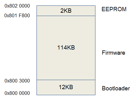
Memory Map
Block Diagram
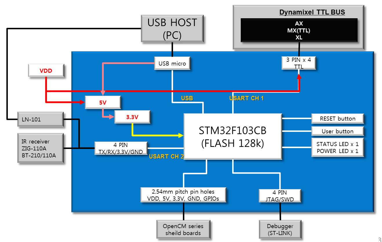
OpenCM9.04’s block diagram is shown below. OpenCM9.04’s schematic is based on 32bit Cortex-M3 core STM32F103CB microcontroller.
The power schematic is designed to cascade through 5V and 3.3V regulators. 5V is supplied to TTL bus and 3.3V is supplied to microcontrollers, 5-pin port and 4-pin communication port.
OpenCM9.04 supports USB2.0 FS. Micro-B connector is used to download the program or perform data communication.
Pin 11(TX1) & Pin 12(RX1) cannot be used simultaneously because USART Channel 1 is assigned to DYNAMIXEL TTL Bus.
USART channel 1 is registered under DYNAMIXEL TTL Bus and cannot be used simultaneously with pin 11(TX1) & 12(RX1).
Layout/Pin Map
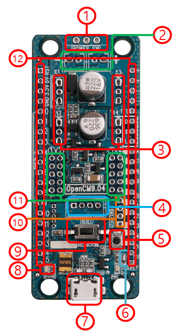
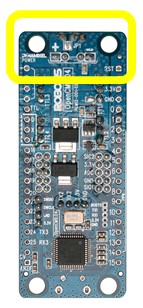
Power Switch
Switch used to control the power supplied to the board and DYNAMIXEL on/off. (Note: the board is always powered ON when USB cable is connected.)
Serial Battery Socket
Connects two LBS-04 Lithium-ion battery.
CAUTION : Do NOT charge the battery while its connected to the board because the user will short the circuit. Be sure to disconnect from the board when charging the battery.
DYNAMIXEL TTL 3 PIN
Port for daisy chaining DYNAMIXEL’s that use 3-pin cables (DYNAMIXEL TTL Bus).
WARNING: To enhance user safety and to prevent proprietary risk or damage, be sure to check the pinout installed on DYNAMIXEL and the board. The Pinout of DYNAMIXEL may differ depending on a manufacturer of connector.
Communication Port
Used from wired/wireless communication using peripheral devices (i.e. BT-410, BT-210, BT-110A, ZIG-110A, LN-101, etc). OpenCM9.04’s 4-pin communication port uses Serial2(USART2).
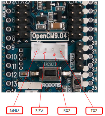
4-pin communication port pinmap
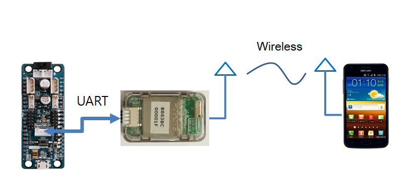
Example : Wireless communication between OpenCM9.04 and a smartphone
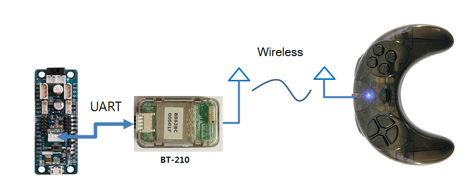
Example : Bluetooth communication using OpenCM9.04 and RC100
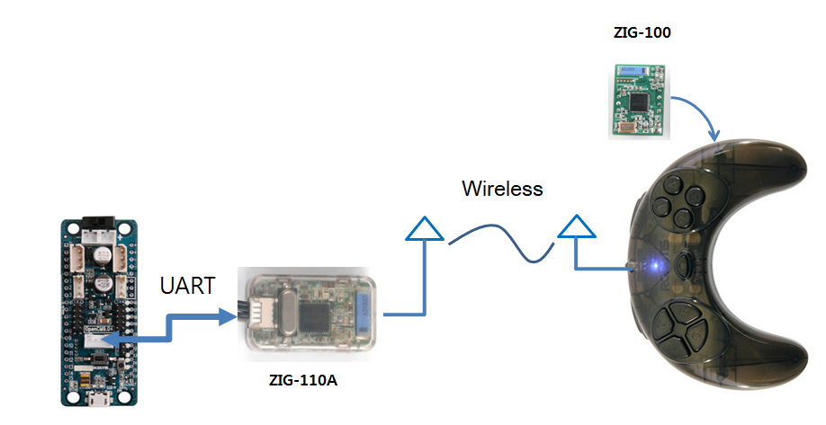
Example : Zigbee communication using OpenCM9.04 and RC100
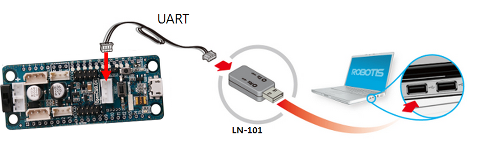
Example : Wired communication using OpenCM9.04 and LN-101
User Button
A button that can be controlled/programmed by the user. Can be used as pin 23 or BOARD_BUTTON_PIN. It can be initialized in setup() as pinMode(23, INPUT_PULLDOWN).
If OpenCM9.04 does not download the program, connect the USB cable while holding down the “User Button”. Status LED will stay lit and the download will be initiated.
OpenCM9.04 can enter a “Emergency Recovery Mode” by using the “User button”
Ext. ADC Ref Jumper
Analog Reference voltage can be modified. Please refer to I/O header section.
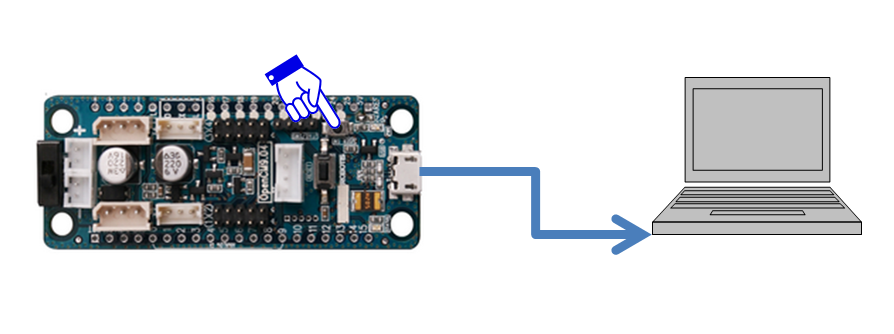
Micro-B USB
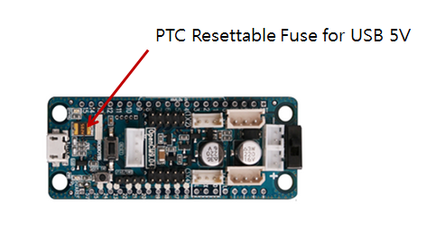
Used to download programs onto OpenCM9.04 and used to communicate with other devices via USB while simultaneously supplying 5V to the board.
Upon connecting the battery, 5V power from USB is automatically disconnected and power is supplied from the battery.
If excessive current is drawn, internal fuse cuts off the current drawn from the 5V USB connection to protect the user’s PC from damage.
[Status LED]
LED used to test OpenCM9.04’s program. The LED turns ON when Pin 14 or BOARD_LED_PIN is HIGH and turns OFF when it’s LOW. PWM control is possible.
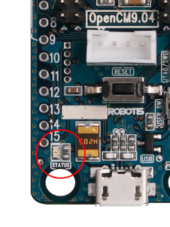
Status LED Position
Reset Button
Imitates the CPU to reset.
JTAG/SWD 4 PIN
Used to connect ST-LINK or other In-Circuit Debugger/Programmer.
JTAG/SWD 4-pin port can be used for various developments by advanced users. ST-LINK connection example is shown below.
Example: ST-LINK and OpenCM9.04 connection
ROBOTIS 5-Pin Port
Used to connect ROBOTIS 5-pin devices (modules).
5-pin port number and instructions
5-pin cable direction
| 5-pin Device Type | Port 1 | Port 2 | Port 3 | Port 4 |
|---|---|---|---|---|
| IR Sensor | O | X | X | O |
| DMS Sensor | O | O | O | O |
| Gyro Sensor | O | O | O | O |
| Touch Sensor | O | O | O | O |
| Color Sensor | X | O | O | X |
| Magnetic Sensor | O | O | O | O |
| Temperature Sensor | O | O | O | O |
| Passive IR Sensor PIR-10 | O | O | O | O |
| LED Module | X | O | O | X |
ROBOTIS sense and LED module compatibility list
I/O Header
OpenCM9.04’s CPU STM32F103CB can be accessed via GPIO pins.
26 GPIO pins (0~25) are digital input/outputs and operates at 3.3V. Digital input either HIGH(3.3V) or LOW(0V).
Digital input’s maximum toggle speed is 18Mhz. (With exception of pin 22 & 23, which has a maximum toggle speed of 2Mhz).
Digital pins can only tolerate up to 3.3V; any voltage input greater than 3.3V may damage the OpenCM9.04.
5V Tolerant Pin : 10, 11, 12, 13, 14, 15, 16, 17, 18, 19, 20, 21
The maximum current these pins can tolerate is 25mA. (exception: pin 22 & 23 can only tolerate 3mA.)
All of OpenCM9.04’s GPIO pins can internally “pull-up” or “pull-down” and can be modified via software. “Pull-up” and “pull-up” resistance is 40KΩ(Typical).
OpenCM9.04 GPIO PinMap
| Name | Arduino Pin | Description |
|---|---|---|
| Serial/SerialUSB | USB Port | |
| Serial1 | N/A | DXL Port |
| Serial2 | A4, A5 | 4PIN UART |
| Serial3 | D24, D25 | OpenCM485 EXP DXL Port |
| SPI1 | A1, A6, A7 | |
| SPI2 | D19, D20, D21 | |
| PWM | A2 ~ D14 | |
| ADC | A0 ~ A9 | |
| LED | D14 | |
| EXTI | A0 ~ D25 | |
| I2C | D24, D25 | |
| BUTTON | D23 | |
| 5PIN #1 | D2, D6, D7 | |
| 5PIN #2 | D3, D8, D9 | |
| 5PIN #3 | D0, D10, D11 | |
| 5PIN #4 | D1, D12, D13 | |
| 4PIN UART | D1, D12, D13 | Serial2 |
- Serial(USART) : 11(TX1), 12(RX1), 4(TX2), 5(RX2), 24(TX3), 25(RX3)
- PWM : 2, 3, 4, 5, 6, 7, 8, 9, 10, 11, 12, 13, 14
- SPI : 0(SS1), 1(SCK1),6(MISO1) ,7(MOSI1), 18(SS2) ,19(SCK2) ,20(MISO2) ,21(MOSI2)
- LED : 14 (BOARD_LED_PIN is defined as 14)
- BUTTON : 23 (BOARD_BUTTON_PIN is defined as 23)
- TWI(I2C) : 24(SCL2), 25(SDA2)
- RST : Pin connect to the CPU Reset signal.
- 5V : outputs 5V when the battery is connected to the board. (Does not output 5V when USB only the USB cable is connected.)
- 3.3V : outputs 3.3V when the power is supplied to the board via battery or USB cable.
- GND : GROUND(-) terminal.
- A0 : Digital I/O and analog input.
- A1 : Digital I/O and analog input. Can be used for SPI channel 1’s SCK clock-pin.
- A2 : Digital I/O, analog input, & PWM output.
- A3 : Digital I/O, analog input, & PWM output.
- A4 : Digital I/O, analog input, & PWM output. USART2(Serial2) TX pin and connected to the TX2 of 4-pin communication port.
- A5 : Digital I/O, analog input, & PWM output. USART2(Serial2) RX pin and connected to the RX2 of 4-pin communication port.
- A6 : Digital I/O, analog input, & PWM output. Can be used as SPI channel 1’s MISO pin.
- A7 : Digital I/O, analog input, & PWM output. Can be used as SPI channel 1’s MISO pin.
- A8 : Digital I/O, analog input, & PWM output.
- A9 Digital I/O, analog input, & PWM output.
- D10 : Digital I/O & PWM output.
- D11 : Digital I/O & PWM output. USART1 TX pin.
- D12 : Digital I/O & PWM output. USART1 RX pin.
- D13 : Digital I/O & PWM output.
- D14 : Digital I/O & PWM output. Pin connected to the Status LED. It’s pre-defined as BOARD_LED_PIN.
- D15 : Digital I/O.
- VCC(+) : +voltage of the board. There are 2 VCC(+) pins. Connected to the + terminal of the battery socket.
- GND(-) :-voltage of the board. There are 2 GND(-) pins. Connected to the + terminal of the battery socket.
- TTL : DYNAMIXEL TTL Bus’s Data line. Used to communicate with 3-pin TTL DYNAMIXEL’s.
- D : Direction Control pin of DYNAMIXEL TTL Bus that controls TX and RX selection.
- X : TX pin of DYNAMIXEL TTL Bus (Serial1).
- L : RX pin of DYNAMIXEL TTL Bus (Serial1).
- D16 : Digital I/O Pin.
- D17 : Digital I/O Pin.
- D18 : Digital I/O Pin.
- D19 : Digital I/O Pin. Can be used for SPI channel 2’s SCK clock pin.
- D20 : Digital I/O Pin. Can be used for SPI channel 2’s MOSI pin.
- D21 : Digital I/O Pin. Can be used for SPI channel 2’s MOSI pin.
- D22 : Digital I/O Pin. Maximum output current is 3mA and maximum toggle speed is 2Mhz.
- D23 : Digital I/O Pin. It’s connected to User Button. If the power is supplied while User Button is pressed, the board initiates Emergency Recovery (Download) Mode. Maximum output current is 3mA and maximum toggle speed is 2Mhz.
- D24 : Digital I/O Pin. Can be used as SCL pin of I2C channel 2 or TX of USART3(Serial3) for OpenCM485 EXP.
- D25 : Digital I/O Pin. Can be used as SDA pin of I2C channel 2 or RX of USART3(Serial3) for OpenCM485 EXP.
- 5V : 5V output pin. JP2 jumper can be modified to connect to AREF pin and change the default voltage to 5V.
- AREF : Connect to CPU’s Analog Reference pin. Voltage can be modified from 3.3V by changing the JP2 jumper (Maximum 5V). Refer to STM32F103CB datasheet for specifications.)
JP2 jumper location and instructions
Example: Changing default Analog Reference voltage(AREF) to 5V by modifying JP2
CAUTION : Check the pin supporting up to 5V once Analog Reference (AREF) has been modified to 5V.
Pin Name Definition
#define LED_BUILTIN             14

#define BOARD_BUTTON_PIN        23  //PC15
#define BOARD_LED_PIN           14  //PB9

#define BOARD_USART1_TX_PIN     11  //D9(PA9)
#define BOARD_USART1_RX_PIN     12  //D10(PA10)
#define BOARD_USART2_TX_PIN     4   //D2 (PA2)
#define BOARD_USART2_RX_PIN     5   //D3 (PA3)
#define BOARD_USART3_TX_PIN     24  //D24 (PB10)
#define BOARD_USART3_RX_PIN     25  //D25 (PB11)

#define BOARD_SPI1_NSS_PIN      0   //D10 (PA4)
#define BOARD_SPI1_MOSI_PIN     7   //D11 PA7
#define BOARD_SPI1_MISO_PIN     6   //D12 PA6
#define BOARD_SPI1_SCK_PIN      1   //D13 PA5
#define BOARD_SPI2_NSS_PIN      18  //D26 PB12
#define BOARD_SPI2_MOSI_PIN     21  //D29 PB15
#define BOARD_SPI2_MISO_PIN     20  //D28 PB14
#define BOARD_SPI2_SCK_PIN      19  //D27 PB13
Pin Function Definition
extern const Pin2PortMapArray g_Pin2PortMapArray[]=
{
  {GPIOA, GPIO_PIN_4,   &hADC1,   ADC_CHANNEL_4 , NULL   ,   NO_PWM       , 0       },  // 0
  {GPIOA, GPIO_PIN_5,   &hADC1,   ADC_CHANNEL_5 , NULL   ,   NO_PWM       , 1       },  // 1
  {GPIOA, GPIO_PIN_0,   &hADC1,   ADC_CHANNEL_0 , &hTIM2 ,   TIM_CHANNEL_1, 2       },  // 2
  {GPIOA, GPIO_PIN_1,   &hADC1,   ADC_CHANNEL_1 , &hTIM2 ,   TIM_CHANNEL_2, 3       },  // 3
  {GPIOA, GPIO_PIN_2,   &hADC1,   ADC_CHANNEL_2 , &hTIM2 ,   TIM_CHANNEL_3, 4       },  // 4
  {GPIOA, GPIO_PIN_3,   &hADC1,   ADC_CHANNEL_3 , &hTIM2 ,   TIM_CHANNEL_4, 5       },  // 5
  {GPIOA, GPIO_PIN_6,   &hADC1,   ADC_CHANNEL_6 , &hTIM3 ,   TIM_CHANNEL_1, 6       },  // 6
  {GPIOA, GPIO_PIN_7,   &hADC1,   ADC_CHANNEL_7 , &hTIM3 ,   TIM_CHANNEL_2, 7       },  // 7
  {GPIOB, GPIO_PIN_0,   &hADC1,   ADC_CHANNEL_8 , &hTIM3 ,   TIM_CHANNEL_3, 8       },  // 8
  {GPIOB, GPIO_PIN_1,   &hADC1,   ADC_CHANNEL_9 , &hTIM3 ,   TIM_CHANNEL_4, 9       },  // 9

  {GPIOA, GPIO_PIN_8,   NULL,     NO_ADC        , &hTIM1 ,   TIM_CHANNEL_1, 10      },  // 10
  {GPIOA, GPIO_PIN_9,   NULL,     NO_ADC        , &hTIM1 ,   TIM_CHANNEL_2, 11      },  // 11
  {GPIOA, GPIO_PIN_10,  NULL,     NO_ADC        , &hTIM1 ,   TIM_CHANNEL_3, 12      },  // 12
  {GPIOB, GPIO_PIN_8,   NULL,     NO_ADC        , &hTIM4 ,   TIM_CHANNEL_3, 13      },  // 13
  {GPIOB, GPIO_PIN_9,   NULL,     NO_ADC        , &hTIM4 ,   TIM_CHANNEL_4, 14      },  // 14 LED
  {GPIOA, GPIO_PIN_15,  NULL,     NO_ADC        , NULL   ,   NO_PWM       , 15      },  // 15
  {GPIOB, GPIO_PIN_3,   NULL,     NO_ADC        , NULL   ,   NO_PWM       , 16      },  // 16
  {GPIOB, GPIO_PIN_4,   NULL,     NO_ADC        , NULL   ,   NO_PWM       , 17      },  // 17
  {GPIOB, GPIO_PIN_12,  NULL,     NO_ADC        , NULL   ,   NO_PWM       , 18      },  // 18
  {GPIOB, GPIO_PIN_13,  NULL,     NO_ADC        , NULL   ,   NO_PWM       , 19      },  // 19

  {GPIOB, GPIO_PIN_14,  NULL,     NO_ADC        , NULL   ,   NO_PWM       , 20      },  // 20
  {GPIOB, GPIO_PIN_15,  NULL,     NO_ADC        , NULL   ,   NO_PWM       , 21      },  // 21
  {GPIOC, GPIO_PIN_14,  NULL,     NO_ADC        , NULL   ,   NO_PWM       , 22      },  // 22
  {GPIOC, GPIO_PIN_15,  NULL,     NO_ADC        , NULL   ,   NO_PWM       , 23      },  // 23 USER_BUTTON
  {GPIOB, GPIO_PIN_10,  NULL,     NO_ADC        , NULL   ,   NO_PWM       , 24      },  // 24
  {GPIOB, GPIO_PIN_11,  NULL,     NO_ADC        , NULL   ,   NO_PWM       , 25      },  // 25


  {GPIOA, GPIO_PIN_13,  NULL,     NO_ADC        , NULL   ,   NO_PWM       , NO_EXTI },  // 26 JTAG SWDIO
  {GPIOA, GPIO_PIN_14,  NULL,     NO_ADC        , NULL   ,   NO_PWM       , NO_EXTI },  // 27 JTAG SWDCLK
  {GPIOB, GPIO_PIN_5,   NULL,     NO_ADC        , NULL   ,   NO_PWM       , NO_EXTI },  // 28 DXL DIR
  {GPIOB, GPIO_PIN_6,   NULL,     NO_ADC        , NULL   ,   NO_PWM       , NO_EXTI },  // 29 DXL TXD
  {GPIOB, GPIO_PIN_7,   NULL,     NO_ADC        , NULL   ,   NO_PWM       , NO_EXTI },  // 30 DXL RXD

  {NULL , 0          ,  NULL,     NO_ADC        , NULL   ,   NO_PWM       , NO_EXTI }
};
Connecting Power
OpenCM board can be powered using 3 types of voltage input:
- LBS-40 battery socket
- Power supplied via +- header pins
- Micro-B USB cable
We recommend using 2 LBS-40 batteries when operating the XL-320.
Example: OpenCM9.04, XL-320, and LBS-40(Li-Ion Battery) connection
LBS-40 battery
We recommend using +- pin to power DYNAMIXEL’s other than XL-320.
Example: OpenCM9.04 and AX12 connection
As displayed in the image below, connect towards the end of both +,- and it can also be connected using other power supply equipment.
(If you see the back side of OpenCM9.04, the +,- in the center is connected as displayed in image A. So, please connect as in the image below)
Picture A
Example : Power Connection
ExamplePower supply cable (Link)
Avoid connecting power to the battery socket and +- pin (shown below). Do not connect an incorrect battery to the battery socket. Only connect LBS-40 onto the battery socket.
CAUTION: Remove either the battery connector or +-header-pin power
CAUTION: Don’t used different types of batteries
It is possible to simultaneously connect the USB port, LBS-40 battery, and +- pin.(Built-in protection)
We recommend supplying the recommended voltage of the DYNAMIXEL when supplying power via +- pin or battery. Higher voltage usage may reduce the DYNAMIXEL’s lifespan or damage the product.
The OpenCM9.04’s maximum tolerable voltage is 16V; voltage input greater than 16V may damage the board.
DYNAMIXEL cannot operate using the power supplied via USB cable, but communication ports and I/O headers can be operated normally.
CAUTION: do NOT charge the LBS-40 battery while it is connected to the board and the board is connected to the PC via USB cable.
Switch Assembly(Type A)
OpenCM9.04 Type A is sold without a power switch and JP1 shorted. To add the power switch, remove the solder connection of JP1 and solder the 2.54mm pitch power switch.
Power switch is included in the OpenCM accessory kit or other switches with the similar pitch can be used.
JP1& Power Switch schematics : Power is supplied to the board if JP1 is connected even without a switch
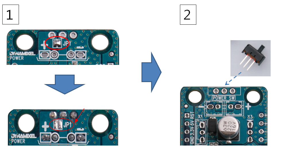
OpenCM9.04 Type A needs to have JP1 disconnected when soldering the switch for it to operate properly
Connector Assembly(Type A)
OpenCM9.04’s DYNAMIXEL 3-Pin TTL pins are all compatible with DYNAMIXEL 3-pin TTL and XL-320 3-pin TTL(mini-type). Thus, both type of pins can be soldered and used.
Both types of 3-pin TTL pins are included in OpenCM Accessory Set.
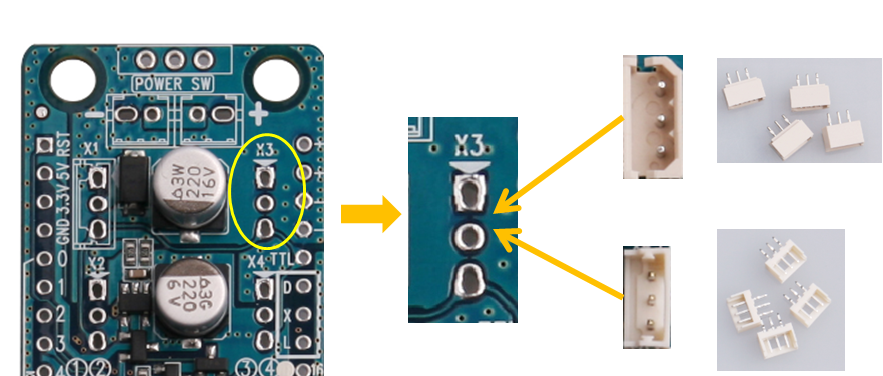
OpenCM9.04 Type A can have 2 types of 3-pin connectors soldered onto the board
NOTE: If DYNAMIXEL-X is used with OpenCM 9.04, JST Type connector should be soldered. For more details, see Using DYNAMIXEL-X.
Development Environment
Supported Software
| Arduino IDE | OpenCM IDE | |
|---|---|---|
| DYNAMIXEL SDK | O | X |
| DYNAMIXELWorkbench | O | X |
| Arduino Libraries | O | X |
| OS X | O | O(10.12.2) |
| Linux | O | O(12.04) |
| Windows | O | O |
OpenCM IDE
OpenCM IDE is deprecated. Please use Arduino IDE.
- OpenCM IDE manual
Arduino IDE
Install on Linux
USB port settings (Linux)
Make the OpenCM9.04 USB port be able to upload the Arduino IDE program without root permission.
wget https://raw.githubusercontent.com/ROBOTIS-GIT/OpenCM9.04/master/99-opencm-cdc.rules
sudo cp ./99-opencm-cdc.rules /etc/udev/rules.d/
sudo udevadm control --reload-rules
sudo udevadm trigger
Compiler Settings (Linux)
Since the OpenCM9.04 libraries is built for 32 bit platform, 64 bit PC needs the 32 bit compiler relevants for the ArduinoIDE.
sudo apt-get install libncurses5-dev:i386
Install the Arduino IDE (Linux)
Download the latest version of Arduino IDE from the official arduino homepage, and install it. Currently, the OpenCM9.04 will be on service in the version 1.6.4 or later.
https://www.arduino.cc/en/Main/Software
Then, extract the downloaded file to the desired folder and execute the installation file from the terminal. In this case, the example shown below makes the folder tools in the user’s top folder (~/). This folder will act as the Arduino IDE folder.
cd ~/tools/arduino-1.8.3
./install.sh
Set the file path of installed Arduino IDE as an absolute path named PATH in the bashrc file. Here recommends to use gedit editor. (Use another editor, if necessary.) Finally, source it to apply the changes.
gedit ~/.bashrc
export PATH=$PATH:$HOME/tools/arduino-1.8.3
source ~/.bashrc
Run the Arduino IDE (Linux)
To run the Arduino IDE on Linux platform, type into the terminal as follows.
arduino
Porting the OpenCM9.04 board to the Arduino IDE (Linux)
Preferences (Linux)
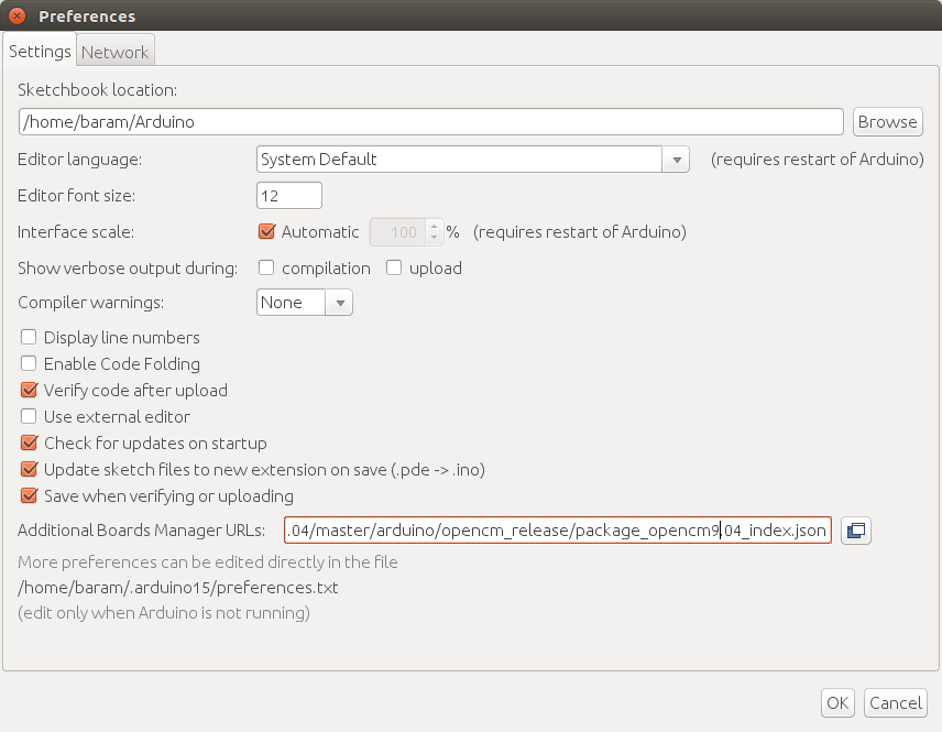
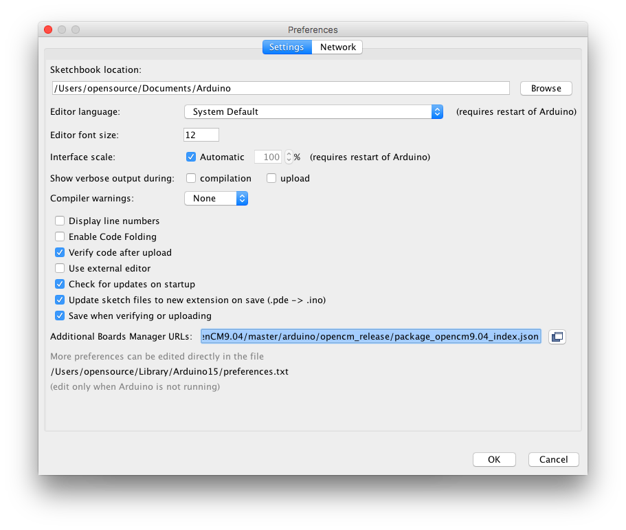
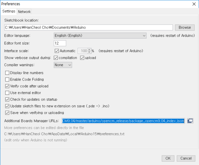
After Arduino IDE is run, click File → Preferences in the top menu of the IDE. When the Preferences window appears, copy and paste following link to the Additional Boards Manager URLs textbox. (This step may take about 20 min.)
Install the OpenCM9.04 package via Boards Manager (Linux)
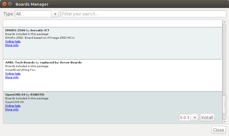
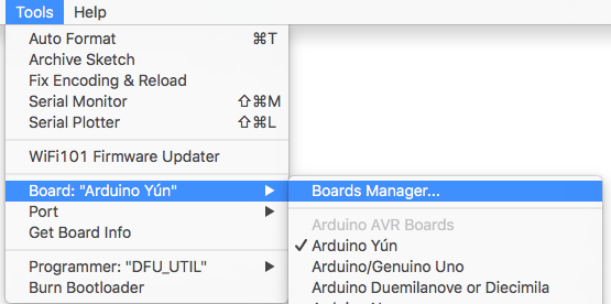
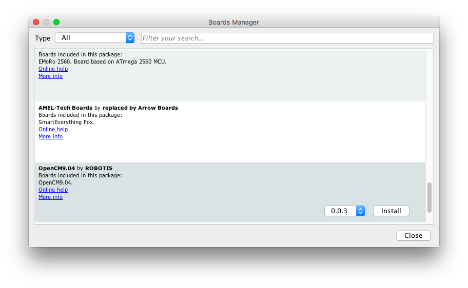
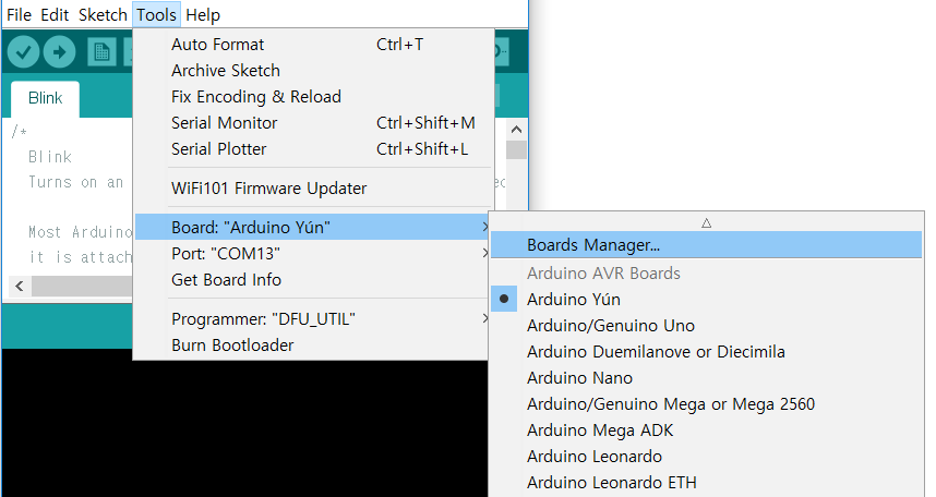
Click Tools → Board → Boards Manager.
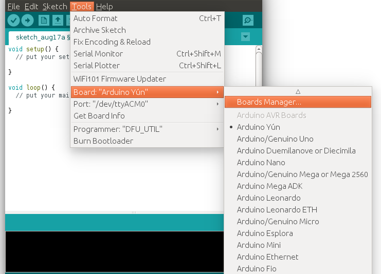
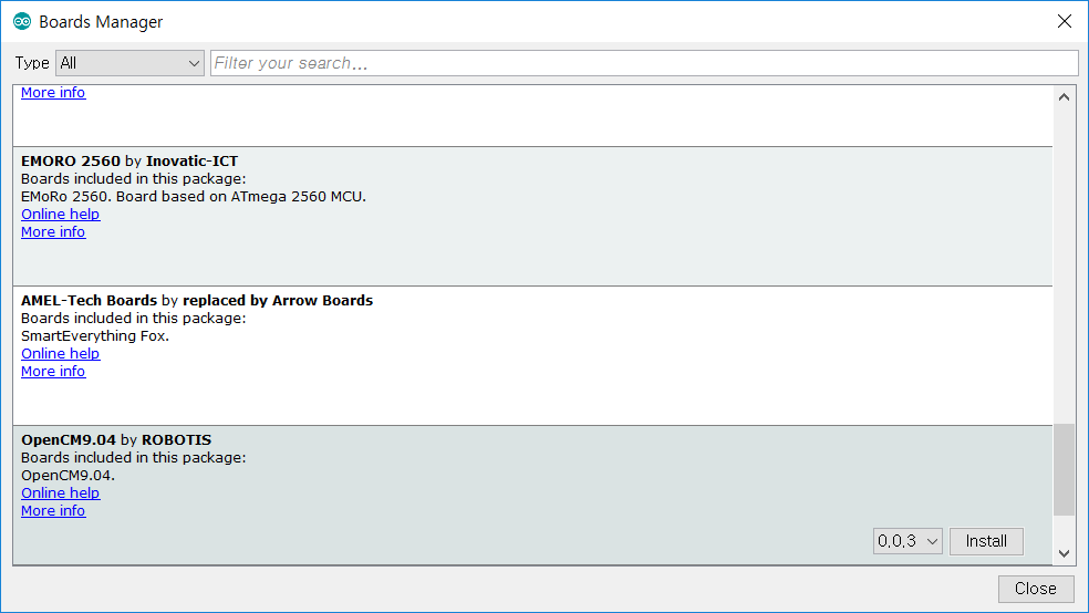
Type OpenCM9.04 into the textbox to find the OpenCM9.04 by ROBOTIS package. After it finds out, click Install.
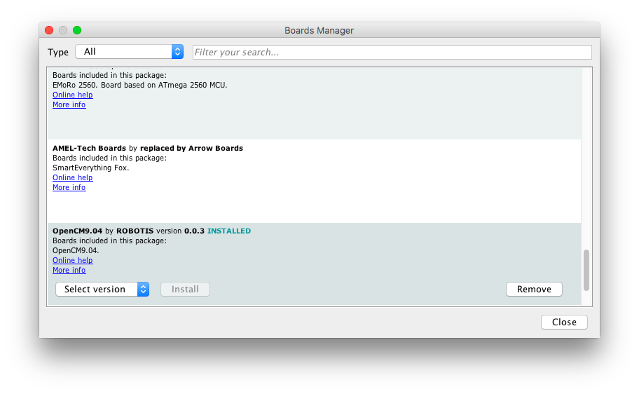
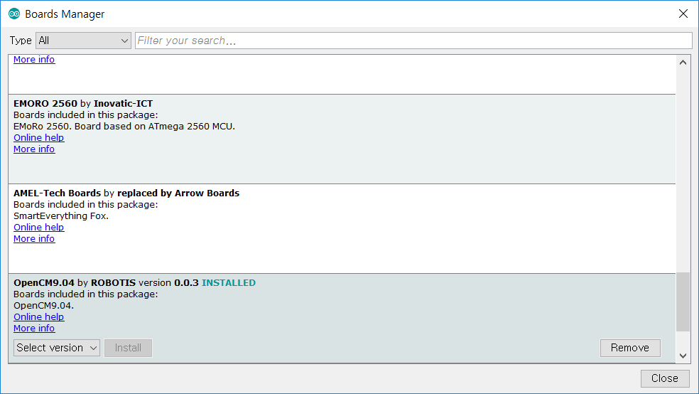
After the installation, “INSTALLED” will be appeared.
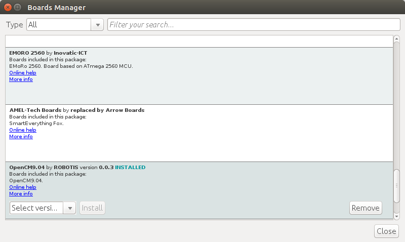
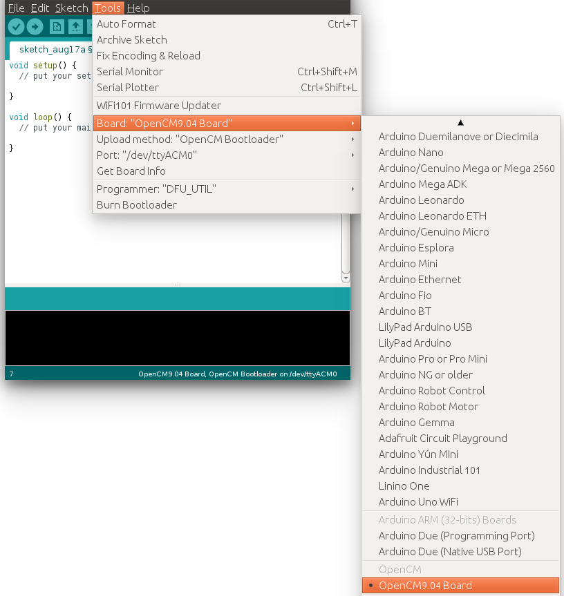
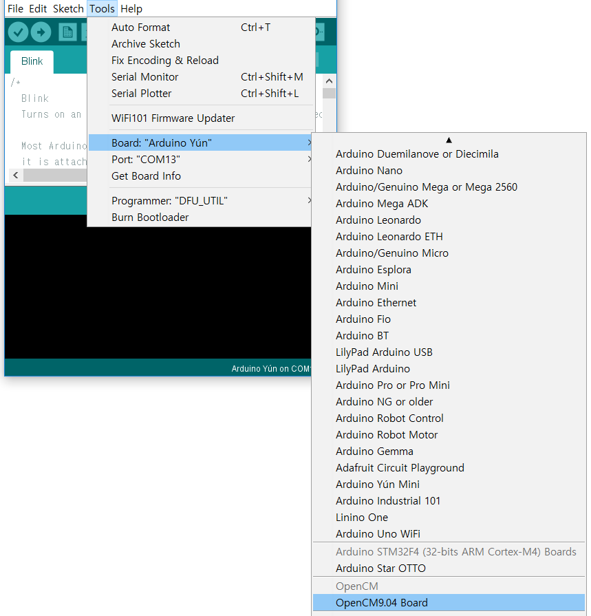
See if OpenCM9.04 Board is now on the list of Tools → Board. Click this to import the OpenCM9.04 Board source.
Port setting (Linux)
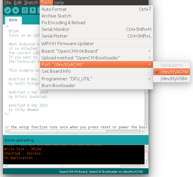
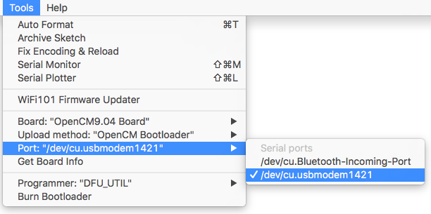
This step shows the port setting for the program uploads. The OpenCM9.04 should be connected to the PC and the OpenCM9.04 via the USB ports.
Select Tools → Port → /dev/ttyACM0.
The value of /dev/ttyACM0 may be different depending on the environment connected to the PC.
Install on Mac
Install the Arduino IDE (Mac)
Download the latest version of Arduino IDE from the official arduino homepage, and install it. Currently, the OpenCM9.04 will be on service in the version 1.6.4 or later.
https://www.arduino.cc/en/Main/Software
Run the Arduino IDE (Mac)
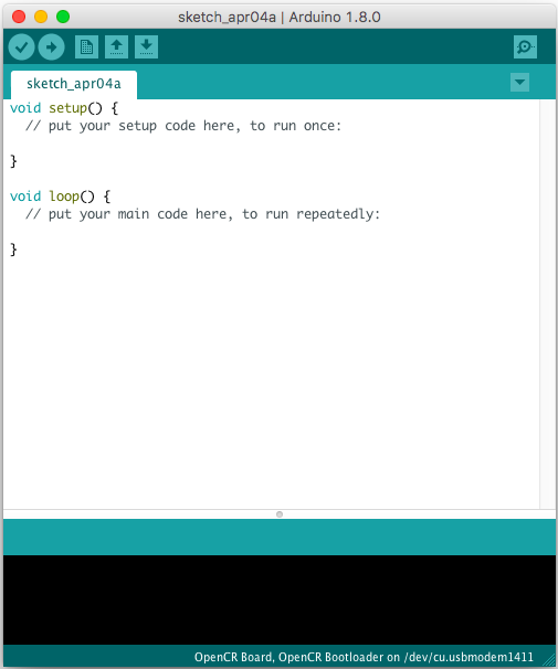
To run the Arduino IDE on Mac platform, click the Arduino IDE icon as follows.
Porting the OpenCM9.04 board to the Arduino IDE (Mac)
Preferences (Mac)
After Arduino IDE is run, click File → Preferences in the top menu of the IDE. When the Preferences window appears, copy and paste following link to the Additional Boards Manager URLs textbox. (This step may take about 20 min.)
Install the OpenCM9.04 package via Boards Manager (Mac)
Click Tools → Board → Boards Manager.
Type OpenCM9.04 into the textbox to find the OpenCM9.04 by ROBOTIS package. After it finds out, click Install.
After the installation, “INSTALLED” will be appeared.
See if OpenCM9.04 Board is now on the list of Tools → Board. Click this to import the OpenCM9.04 Board source.
Port setting (Mac)
This step shows the port setting for the program uploads. The OpenCM9.04 should be connected to the PC and the OpenCM9.04 via the USB ports.
Select Tools → Port → /dev/ttyACM0.
The value of /dev/ttyACM0 may be different depending on the environment connected to the PC.
Install on Windows
Install Virtual COM Port Driver
To use OpenCM9.04’s USB port as a serial port in Windows, you need a USB CDC driver.
Download the latest version of Arduino IDE from the official arduino homepage, and install it. Currently, the OpenCM 9.04 will be on service in the version 1.6.4 or later.
https://www.arduino.cc/en/Main/Software
The Arduino IDE for Windows is available as an installation version and a compressed version, so you can install it using your preferred method.
Porting the OpenCM 9.04 board to the Arduino IDE (Windows)
Preferences (Windows)
After Arduino IDE is run, click File → Preferences in the top menu of the IDE. When the Preferences window appears, copy and paste following link to the Additional Boards Manager URLs textbox. (This step may take about 20 min.)
Install the OpenCM9.04 package via Boards Manager (Windows)
Click Tools → Board → Boards Manager.
Type OpenCM9.04 into the textbox to find the OpenCM9.04 by ROBOTIS package. After it finds out, click Install.
After the installation, “INSTALLED” will be appeared.
See if OpenCM9.04 Board is now on the list of Tools → Board. Click this to import the OpenCM9.04 Board source.
Port setting (Windows)
This step shows the port setting for the program uploads. The OpenCM9.04 should be connected to the PC and the OpenCM9.04 via the USB ports.
Select Tools > Port > COM1.
The value of COM1 may be different depending on the environment connected to the PC.
Upload sketch
The way to upload the sketch to the OpenCM9.04 board is similar to the way other common arduino boards do such as Arduino Uno.
Connect the OpenCM9.04 to the PC via USB cable and click on the Upload icon.
Make sure that the board is properly entering the Bootloader (See the resulting output from the Arduino IDE), otherwise the OpenCM9.04 will fail to download the sketch.
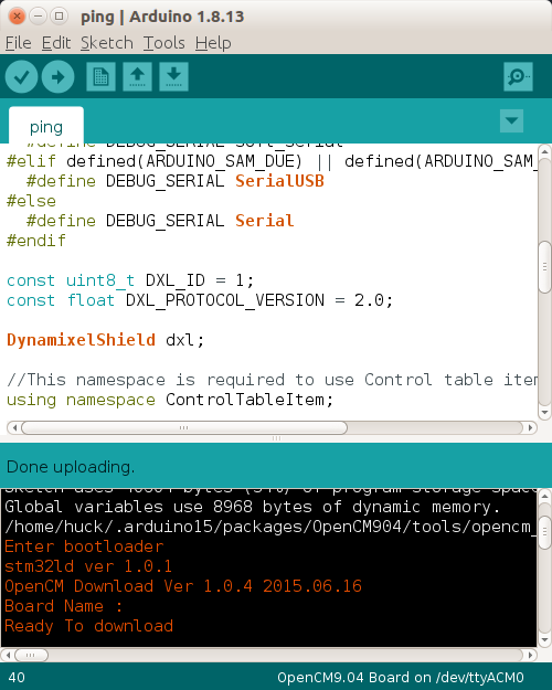
Note: Uploading error could be occured by a firmware issue installed on the board. If you enters any error while uploading the code to the board, see User Button
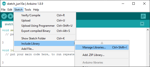
Library API
There are three ways to add libraries to the Arduino IDE.
- Using the Library Manager
- Importing a .zip Library
- Manual installation
Each way is described in detail in the Arduino Official Guide, so please refer to it if necessary.
Below is an example of using the Library Manager.
Search for DYNAMIXEL2Arduino from the Library Manager and install the library.
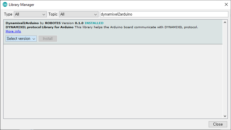
If the DYNAMIXEL2Arduino library has been successfully installed, useful examples to control DYNAMIXEL can be found under the DYNAMIXEL2Arduino category.
Dynamixel2Arduino Library
Dynamixel2Arduino Class
- begin()
- getPortBaud()
- ping()
- scan()
- getModelNumber()
- setID()
- setProtocol()
- setBaudrate()
- torqueOn()
- torqueOff()
- ledOn()
- ledOff()
- setOperatingMode()
- setGoalPosition()
- getPresentPosition()
- setGoalVelocity()
- getPresentVelocity()
- setGoalPWM()
- getPresentPWM()
- setGoalCurrent()
- getPresentCurrent()
- getTorqueEnableStat()
- readControlTableItem()
- writeControlTableItem()
Master Class
DYNAMIXEL2Arduino class inherits below public functions from the Master class.
Examples
You can find more examples after installing DYNAMIXEL2Arduino library
LED
It is a built-in LED test on the OpenCM9.04 board.
Test Example for LED
There are 1 LED available in OpenCM9.04, The LED connected to base 14 of Arduino.
When the built-in LED pin is output as High / Low, the LED turns on / off.
#define BOARD_LED_PIN 14
It is a code that sequentially turns on and off all the LEDs.
int led_pin = 14;

void setup() {
  // Set up the built-in LED pin as an output:
  pinMode(led_pin, OUTPUT);

  Serial.begin(115200);
}

void loop() {
  int i;

  digitalWrite(led_pin, HIGH);  // set to as HIGH LED is turn-off
  Serial.println("led_off");
  delay(100);                   // Wait for 0.1 second
  digitalWrite(led_pin, LOW);   // set to as LOW LED is turn-on
  Serial.println("led_on");
  delay(100);                   // Wait for 0.1 second
}
Button
It is a built-in BUTTON test on the OpenCM9.04 board.
Test Example for Button
There is one Push switche in OpenCM9.04. The pin number is defined as below, so you can see the status of the current button when you input the data of that pin.
#define BOARD_BUTTON_PIN 23
It is a code that outputs the button input status in serial. In order to use the built-in buttons, you need to set the port to pull-down.
void setup(){
  Serial.begin(115200);

  pinMode(BOARD_BUTTON_PIN, INPUT_PULLDOWN);
}

void loop(){
  int push_state;

  push_state  = digitalRead(BOARD_BUTTON_PIN)<<0;

  Serial.print("push_state = ");
  Serial.println(push_state, BIN);

  delay(100);
}
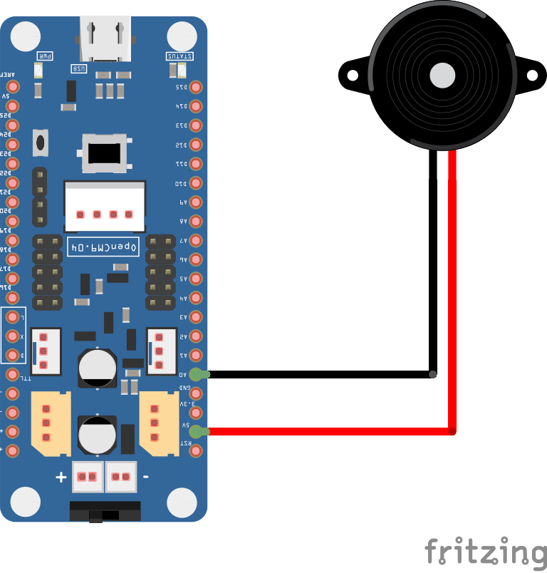
Buzzer
Buzzer can be driven using Arduino tone API. Buzzer-enabled pins are available on all I / O pins in OpenCM 9.04.
Connection with Buzzer
Arduino code for Buzzer
The following example shows a change to the Buzzer pin in the basic tone example provided by Arduino, which uses the Buzzer to play the melody.
#include "pitches.h"

int buzzer_pin = A0;

// notes in the melody:
int melody[] = {
  NOTE_C4, NOTE_G3, NOTE_G3, NOTE_A3, NOTE_G3, 0, NOTE_B3, NOTE_C4
};

// note durations: 4 = quarter note, 8 = eighth note, etc.:
int noteDurations[] = {
  4, 8, 8, 4, 4, 4, 4, 4
};

void setup() {
  // iterate over the notes of the melody:
  for (int thisNote = 0; thisNote < 8; thisNote++) {

    // to calculate the note duration, take one second
    // divided by the note type.
    //e.g. quarter note = 1000 / 4, eighth note = 1000/8, etc.
    int noteDuration = 1000 / noteDurations[thisNote];
    tone(buzzer_pin, melody[thisNote], noteDuration);

    // to distinguish the notes, set a minimum time between them.
    // the note's duration + 30% seems to work well:
    int pauseBetweenNotes = noteDuration * 1.30;
    delay(pauseBetweenNotes);
    // stop the tone playing:
    noTone(buzzer_pin);
  }
}
PWM
This is the PWM output test from the pin of the OpenCM9.04 board.
Test Example for PWM
The analogueWrite is used to output the PWM duty ratio to the corresponding ports. The resolution is 8 bits, from 0 to 255, and the frequency is 10 KHz.
OpenCM 9.04 has 13 PWM pins in total. This is an example of PWM output on the six pins.
/*
 * PWM Pins : 2, 3, 4, 5, 6, 7, 8, 9, 10, 11, 12, 13, 14
 */

int pwm_pins[6] = { 2, 3, 4, 5, 6, 7 };

void setup() {
  // put your setup code here, to run once:
}

void loop() {
  // put your main code here, to run repeatedly:
  int i;
  static uint8_t pwm_out = 0;

  for( i=0; i<6; i++ )
  {
    analogWrite(pwm_pins[i], pwm_out++);
  }
  delay(100);
}
EEPROM
It is the EEPROM library test of OpenCM9.04 board.
Test
OpenCM9.04 does not have EEPROM memory, so it emulates a part of flash memory built in STM32F103 into EEPROM. The method of emulation was provided by ST as an example.
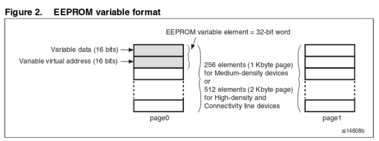
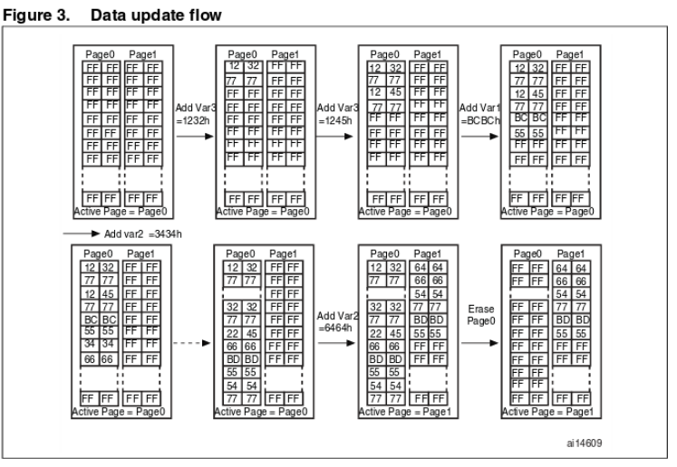
The area used as EEPROM is 0x0801F800 ~ 0x08020000 (2KBytes) as shown below. Two sectors are used.
32 bits are used to store one data, the lower 16 bits are the data to be stored, and the upper 16 bits indicate the address of the corresponding data. When storing data, it is always stored in the new location. When you use one page while saving the data, only the latest values from the saved page are copied to the new page and the existing page is deleted. As a result, the number of flash memory erasures is reduced, thereby increasing the write-through life.
To use the EEPROM library, a header must be added, and the maximum size of the current EEPROM is 512bytes. Since the EEPROM library has ported what is supported in Arduino, the basic usage method is the same as that used in other existing Arduino boards. For more information on how to use it, please refer to the Arduino site.
https://www.arduino.cc/en/Reference/EEPROM
#include <EEPROM.h>
#include <EEPROM.h>

void setup() {
  // put your setup code here, to run once:
  Serial.begin(115200);
}

void loop() {
  // put your main code here, to run repeatedly:
  uint32_t tTime;
  static int i = 0;


  if( (millis()-tTime) > 100 )
  {
    Serial.print(EEPROM.read(0));
    Serial.print("\t");
    Serial.print(EEPROM.read(1));
    Serial.print("\t");
    Serial.print(EEPROM.read(2));
    Serial.println("\t");

    tTime = millis();
  }

  if (Serial.available())
  {
    uint8_t inByte = Serial.read();

    if( inByte == '1' )
    {
      EEPROM.write(0, i+1);
      EEPROM.write(1, i+2);
      EEPROM.write(2, i+3);
      i++;
    }
  }
}
Servo
- Servo library is used to drive RC servo for RC.
- RC Servo Library uses OpenCM9.04 hardware timer and can be used by connecting to PWM output pin.
- A2 to D14 pins are PWM output pins.
- Be careful when using Servo library because other functions using hardware timer can not be used at the same time.
- See the list below for the hardware and channels used.
{GPIOA, GPIO_PIN_0,   &hADC1,   ADC_CHANNEL_0 , &hTIM2 ,   TIM_CHANNEL_1, 2       },  // 2
{GPIOA, GPIO_PIN_1,   &hADC1,   ADC_CHANNEL_1 , &hTIM2 ,   TIM_CHANNEL_2, 3       },  // 3
{GPIOA, GPIO_PIN_2,   &hADC1,   ADC_CHANNEL_2 , &hTIM2 ,   TIM_CHANNEL_3, 4       },  // 4
{GPIOA, GPIO_PIN_3,   &hADC1,   ADC_CHANNEL_3 , &hTIM2 ,   TIM_CHANNEL_4, 5       },  // 5
{GPIOA, GPIO_PIN_6,   &hADC1,   ADC_CHANNEL_6 , &hTIM3 ,   TIM_CHANNEL_1, 6       },  // 6
{GPIOA, GPIO_PIN_7,   &hADC1,   ADC_CHANNEL_7 , &hTIM3 ,   TIM_CHANNEL_2, 7       },  // 7
{GPIOB, GPIO_PIN_0,   &hADC1,   ADC_CHANNEL_8 , &hTIM3 ,   TIM_CHANNEL_3, 8       },  // 8
{GPIOB, GPIO_PIN_1,   &hADC1,   ADC_CHANNEL_9 , &hTIM3 ,   TIM_CHANNEL_4, 9       },  // 9

{GPIOA, GPIO_PIN_8,   NULL,     NO_ADC        , &hTIM1 ,   TIM_CHANNEL_1, 10      },  // 10
{GPIOA, GPIO_PIN_9,   NULL,     NO_ADC        , &hTIM1 ,   TIM_CHANNEL_2, 11      },  // 11
{GPIOA, GPIO_PIN_10,  NULL,     NO_ADC        , &hTIM1 ,   TIM_CHANNEL_3, 12      },  // 12
{GPIOB, GPIO_PIN_8,   NULL,     NO_ADC        , &hTIM4 ,   TIM_CHANNEL_3, 13      },  // 13
{GPIOB, GPIO_PIN_9,   NULL,     NO_ADC        , &hTIM4 ,   TIM_CHANNEL_4, 14      },  // 14 LED
Connection with Servo
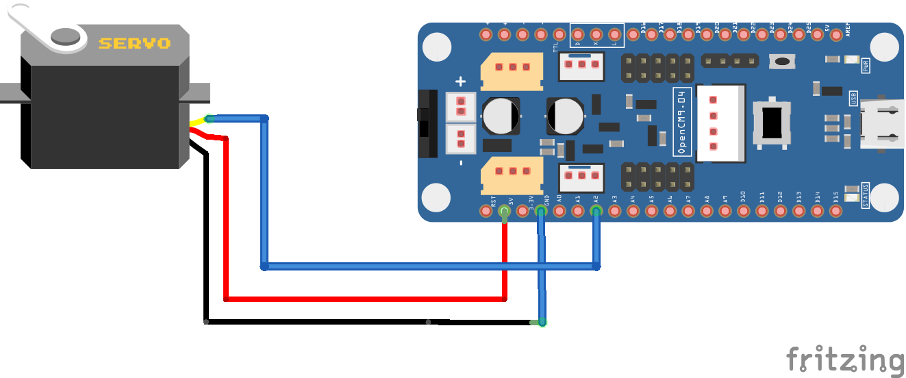
Arduino code for servo
This is an example of a Servo library and uses the A2 pin of OpenCM9.04. The range of the input value is 0 to 180 degrees.
#include <Servo.h>

Servo myservo;  // create servo object to control a servo

void setup() {
  myservo.attach(A2);  // attaches the servo on pin 2 to the servo object
}

void loop() {
  myservo.write(0);                    // sets the servo position according to the scaled value
  delay(1000);                         // waits for the servo to get there
  myservo.write(180);                  // sets the servo position according to the scaled value
  delay(1000);                         // waits for the servo to get there
}
SD Card
The Arduino IDE includes an SD card control library using the SPI library. OpenCM 9.04 supports the default SD library.
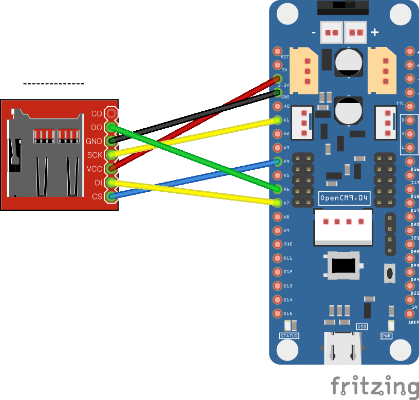
Connection with SD Card
-
SD Card Connection(SPI port)
Arduino code for SD Card
The cardInfo example from the SD library and displays the file list after initializing the SD card. OpenCM9.04 SPI1 is used, and CS pin is used as No. 4.
// include the SD library:
#include <SPI.h>
#include <SD.h>

// set up variables using the SD utility library functions:
Sd2Card card;
SdVolume volume;
SdFile root;

// change this to match your SD shield or module;
// Arduino Ethernet shield: pin 4
// Adafruit SD shields and modules: pin 10
// Sparkfun SD shield: pin 8
// MKRZero SD: SDCARD_SS_PIN
const int chipSelect = 4;

void setup() {
  // Open serial communications and wait for port to open:
  Serial.begin(9600);
  while (!Serial) {
    ; // wait for serial port to connect. Needed for native USB port only
  }

  Serial.print("\nInitializing SD card...");

  // we'll use the initialization code from the utility libraries
  // since we're just testing if the card is working!
  if (!card.init(SPI_HALF_SPEED, chipSelect)) {
    Serial.println("initialization failed. Things to check:");
    Serial.println("* is a card inserted?");
    Serial.println("* is your wiring correct?");
    Serial.println("* did you change the chipSelect pin to match your shield or module?");
    return;
  } else {
    Serial.println("Wiring is correct and a card is present.");
  }

  // print the type of card
  Serial.print("\nCard type: ");
  switch (card.type()) {
    case SD_CARD_TYPE_SD1:
      Serial.println("SD1");
      break;
    case SD_CARD_TYPE_SD2:
      Serial.println("SD2");
      break;
    case SD_CARD_TYPE_SDHC:
      Serial.println("SDHC");
      break;
    default:
      Serial.println("Unknown");
  }

  // Now we will try to open the 'volume'/'partition' - it should be FAT16 or FAT32
  if (!volume.init(card)) {
    Serial.println("Could not find FAT16/FAT32 partition.\nMake sure you've formatted the card");
    return;
  }

  // print the type and size of the first FAT-type volume
  uint32_t volumesize;
  Serial.print("\nVolume type is FAT");
  Serial.println(volume.fatType(), DEC);
  Serial.println();

  volumesize = volume.blocksPerCluster();    // clusters are collections of blocks
  volumesize *= volume.clusterCount();       // we'll have a lot of clusters
  volumesize *= 512;                            // SD card blocks are always 512 bytes
  Serial.print("Volume size (bytes): ");
  Serial.println(volumesize);
  Serial.print("Volume size (Kbytes): ");
  volumesize /= 1024;
  Serial.println(volumesize);
  Serial.print("Volume size (Mbytes): ");
  volumesize /= 1024;
  Serial.println(volumesize);

  Serial.println("\nFiles found on the card (name, date and size in bytes): ");
  root.openRoot(volume);

  // list all files in the card with date and size
  root.ls(LS_R | LS_DATE | LS_SIZE);
}

void loop(void) {

}
MS5540S
The MS5540S is a sensor that can measure water pressure and can calculate the depth in water by measuring the water pressure. SPI communication is used.
Connection with MS5540S
| MS5540S | OpenCM9.04 | etc |
|---|---|---|
| VCC | 3.3V | |
| GND | GND | |
| MCLK | D13 | 32.768Khz |
| DIN | A7 | MOSI |
| DOUT | A6 | MISO |
| SCLK | A1 | SCK |
Arduino code for MS5540S
Use SPI1 of OpenCM9.04 and input the clock of 32.768Khz to MCLK of MS5540S sensor. The analogWriteFreq function, which can adjust the frequency of the PWM pin of OpenCM 9.04, generates a clock of 32.768 KHz.
#include <SPI.h>

float water_depth;
float water_temp;

void ms5540s_reset();
void ms5540s_setup();
void ms5540s_loop();

void setup() {
  // put your setup code here, to run once:
  Serial.begin(115200);
  ms5540s_setup();
}

void loop() {
  // put your main code here, to run repeatedly:
  static uint32_t pre_time[2];

  if( (millis() - pre_time[0]) >= 10 )
  {
    pre_time[0] = millis();
    ms5540s_loop();
  }

  if( (millis() - pre_time[1]) >= 100 )
  {
    pre_time[1] = millis();
    Serial.print(water_depth);
    Serial.print(" m\t");
    Serial.print(water_temp);
    Serial.println(" 'C");
  }
}

////////////////////////////////////////////
// MS5540S
////////////////////////////////////////////

#define FRESH_WATER  1000.0 // [kg/m^3]
#define SEA_WATER    1030.0 // [kg/m^3]


const int clock = 13;

const float water_type = SEA_WATER;
const int get_interval = 35;
static int ms5540s_state = 0;

float g;
float latitude = 37.0;
float lat_rad = ((37.0/57.29578) * PI / 180);
float x = sin(lat_rad)*sin(lat_rad);

/*---------------------------------------------------------------------------
     TITLE   : ms5540s_reset
     WORK    :
     ARG     : void
     RET     : void
---------------------------------------------------------------------------*/
void ms5540s_reset() //this function keeps the sketch a little shorter
{
 SPI.setDataMode(SPI_MODE0);
 SPI.transfer(0x15);
 SPI.transfer(0x55);
 SPI.transfer(0x40);
}

/*---------------------------------------------------------------------------
     TITLE   : ms5540s_setup
     WORK    :
     ARG     : void
     RET     : void
---------------------------------------------------------------------------*/
void ms5540s_setup() {
 SPI.begin(); //see SPI library details on arduino.cc for details
 SPI.setBitOrder(MSBFIRST);
 SPI.setClockDivider(SPI_CLOCK_DIV32); //divide 16 MHz to communicate on 500 kHz
 pinMode(clock, OUTPUT);
 analogWriteFreq(clock, 32768);
 delay(100);
}

/*---------------------------------------------------------------------------
     TITLE   : ms5540s_loop
     WORK    :
     ARG     : void
     RET     : void
---------------------------------------------------------------------------*/
void ms5540s_loop()
{
  static uint32_t tTime;

  unsigned int word1 = 0;
  unsigned int word11 = 0;
  unsigned int word2 = 0;
  unsigned int word3 = 0;
  byte word22 = 0;
  byte word33 = 0;
  unsigned int word4 = 0;
  byte word44 = 0;
  static long c1;
  static long c2;
  static long c3;
  static long c4;
  static long c5;
  static long c6;
  unsigned int presMSB = 0; //first byte of value
  unsigned int presLSB =0; //last byte of value
  static unsigned int D1 = 0;
  unsigned int tempMSB = 0; //first byte of value
  unsigned int tempLSB = 0; //last byte of value
  static unsigned int D2 = 0;
  long UT1 = 0;
  long dT = 0;
  long TEMP = 0;
  long OFF = 0;
  long SENS = 0;

  float p;
  static long PCOMP = 0;
  static long PCOMP2 = 0;
  static long PH2 = 0;
  static float TEMPREAL = 0;
  static float DEPTH = 0;

  long dT2 = 0;
  static float TEMPCOMP = 0;

  bool ret = false;

//////////////////////////////////////////
  switch( ms5540s_state )
  {
    case 0:
      analogWrite (clock, 128) ;
      ms5540s_reset();//resets the sensor - caution: afterwards mode = SPI_MODE0!
      //Calibration word 1
      word1 = 0;
      word11 = 0;
      SPI.transfer(0x1D); //send first byte of command to get calibration word 1
      SPI.transfer(0x50); //send second byte of command to get calibration word 1
      SPI.setDataMode(SPI_MODE1); //change mode in order to listen
      word1 = SPI.transfer(0x00); //send dummy byte to read first byte of word
      word1 = word1 << 8; //shift returned byte
      word11 = SPI.transfer(0x00); //send dummy byte to read second byte of word
      word1 = word1 | word11; //combine first and second byte of word
      ms5540s_reset();//resets the sensor
      //Calibration word 2; see comments on calibration word 1
      word2 = 0;
      word22 = 0;
      SPI.transfer(0x1D);
      SPI.transfer(0x60);
      SPI.setDataMode(SPI_MODE1);
      word2 = SPI.transfer(0x00);
      word2 = word2 <<8;
      word22 = SPI.transfer(0x00);
      word2 = word2 | word22;
      ms5540s_reset();//resets the sensor
      //Calibration word 3; see comments on calibration word 1
      word3 = 0;
      word33 = 0;
      SPI.transfer(0x1D);
      SPI.transfer(0x90);
      SPI.setDataMode(SPI_MODE1);
      word3 = SPI.transfer(0x00);
      word3 = word3 <<8;
      word33 = SPI.transfer(0x00);
      word3 = word3 | word33;
      ms5540s_reset();//resets the sensor
      //Calibration word 4; see comments on calibration word 1
      word4 = 0;
      word44 = 0;
      SPI.transfer(0x1D);
      SPI.transfer(0xA0);
      SPI.setDataMode(SPI_MODE1);
      word4 = SPI.transfer(0x00);
      word4 = word4 <<8;
      word44 = SPI.transfer(0x00);
      word4 = word4 | word44;
////////////////////////////////////////////////////////////////////

      c1 = (word1 >> 1);
      c2 = ((word3 & 0x3F) << 6) | ((word4 & 0x3F));
      c3 = (word4 >> 6);
      c4 = (word3 >> 6);
      c5 = (word2 >> 6) | ((word1 & 0x1) << 10);
      c6 = (word2 & 0x3F);
      ms5540s_reset();//resets the sensor

      //Temperature:
      SPI.transfer(0x0F); //send first byte of command to get temperature value
      SPI.transfer(0x20); //send second byte of command to get temperature value

      tTime = millis();
      ms5540s_state = 1;
      break;

    case 1:
      if( (millis()-tTime) >= get_interval )
      {
        ms5540s_state = 2;
      }
      break;

    case 2:
      SPI.setDataMode(SPI_MODE1); //change mode in order to listen
      tempMSB = SPI.transfer(0x00); //send dummy byte to read first byte of value
      tempMSB = tempMSB << 8; //shift first byte
      tempLSB = SPI.transfer(0x00); //send dummy byte to read second byte of value
      D2 = tempMSB | tempLSB; //combine first and second byte of value
      ms5540s_reset();//resets the sensor

     //Pressure:
      SPI.transfer(0x0F); //send first byte of command to get pressure value
      SPI.transfer(0x40); //send second byte of command to get pressure value

      tTime = millis();
      ms5540s_state = 3;
      break;

    case 3:
      if( (millis()-tTime) >= get_interval )
      {
        ms5540s_state = 4;
      }
      break;

    case 4:
      SPI.setDataMode(SPI_MODE1); //change mode in order to listen
      presMSB = SPI.transfer(0x00); //send dummy byte to read first byte of value
      presMSB = presMSB << 8; //shift first byte
      presLSB = SPI.transfer(0x00); //send dummy byte to read second byte of value
      D1 = presMSB | presLSB;

      UT1 = (c5 * 8) + 20224;   //calculate calibration temperature
      //calculate actual temperature
      dT =(D2 - UT1);
      TEMP = 200 + ((dT * (c6 + 50))/1024);
      //TEMP = 20 + (dT * c6);
      //calculate temperature compensated pressure
      OFF = (c2*4) + (((c4 - 512) * dT)/4096);
      SENS = c1 + ((c3 * dT)/1024) + 24576;

      //0.1 mbar resolution
      PCOMP = ((((((SENS * (D1 - 7168))/16384)- OFF)*10)/32)+(250*10))/10;

      if(PCOMP > 1000)
      {
       PH2 = (-5*((PCOMP-1000)*(PCOMP-1000)))/(1<<19);
      }
      else
      {
        PH2 = 0;
      }
      PCOMP2 = PCOMP - PH2;

       // smaller than 1atm (1,013.25 hPa)
      //if(PCOMP2 < 1013.25) PCOMP2 = 0;

      TEMPREAL = TEMP/10;

      dT2 = dT - ((dT >> 7 * dT >> 7) >> 3);
      TEMPCOMP = (200 + (dT2*(c6+100) >>11))/10;

      if(water_type == FRESH_WATER)
      {
        DEPTH = PCOMP2 * 1.019716 / 1000;   // 1000mb = bar
      }
      else
      {
        g = 9.780318*(1.0 + ((5.2788*1/1000) + 2.36*1/100000 * x)*x) + (1.092*1/1000000*PCOMP2);
        DEPTH = (((((-1.82*1/1000000000000000)*PCOMP2 + (2.279*1/10000000000))*PCOMP2 - (2.2512*1/100000))*PCOMP2 + 9.72659)*PCOMP2)/g;
      }

      water_depth = DEPTH;
      water_temp  = TEMPCOMP;
/*
      Serial.print("Pressure : ");
      Serial.print(PCOMP);
      Serial.println(" mb(millibar)");
      Serial.print("Temperature : ");
      Serial.print(TEMPCOMP);
      Serial.println(" 'C");
      Serial.print("WaterDepth : ");
      Serial.print(DEPTH);
      Serial.println(" m");
      Serial.println();
*/
      ret = true;
      ms5540s_state = 0;
      break;

    default:
      ms5540s_state = 0;
      break;
  }
}
MPU6050 DMP
The MPU6050 is a sensor consisting of three axes of acceleration / three axes of gyro. If a dedicated processor called DMP is used in the MPU6050, the MPU6050 performs sensor fusion processing for obtaining Roll / Pitch / Yaw.
Connection with MPU6050 DMP
| MPU6050 | OpenCM9.04 | etc |
|---|---|---|
| VCC | 5V | |
| GND | GND | |
| SCL | D24 | I2C2 |
| SDA | D25 | I2C2 |
| INT | A2 |
Arduino code for MPU6050 DMP
Enable the DMP function of MPU6050 and output Roll / Pitch / Yaw value in serial every 50ms. The full source code is downloaded from the link below.
- Source code download link https://github.com/ROBOTIS-GIT/OpenCM9.04/blob/master/arduino/opencm_arduino/examples/Exam_MPU6050.zip
#include "mpu.h"

MPU6050 mpu;

void setup()
{
  Serial.begin(115200);

  dmpDataReady();
  dmp_setup();
}

void loop()
{
  static uint32_t tTime[4];

  dmp_loop();

  if( (millis() - tTime[2]) >= 50 )
  {
    tTime[2] = millis();
    Serial.print("roll : ");
    Serial.print(String(roll, 2));
    Serial.print("  pitch : ");
    Serial.print(String(pitch, 2));
    Serial.print("  yaw : ");
    Serial.println(String(yaw, 2));
  }
}

////////////////////////////////////////
//        IMU
/////////////////////////////////////////
/*---------------------------------------------------------------------------
     TITLE   : dmpDataReady
     WORK    :
     ARG     : void
     RET     : void
---------------------------------------------------------------------------*/
void dmpDataReady() {
    mpuInterrupt = true;
}

/*---------------------------------------------------------------------------
     TITLE   : dmp_setup
     WORK    :
     ARG     : void
     RET     : void
---------------------------------------------------------------------------*/
void dmp_setup() {
    I2Cdev::begin(400);

    // initialize device
    Serial.println(F("Initializing I2C devices..."));
    mpu.initialize();
    pinMode(INTERRUPT_PIN, INPUT);

    // verify connection
    Serial.println(F("Testing device connections..."));
    Serial.println(mpu.testConnection() ? F("MPU6050 connection successful") : F("MPU6050 connection failed"));

    // wait for ready
    Serial.println(F("\nSend any character to begin DMP programming and demo: "));
  //  while (Serial.available() && Serial.read()); // empty buffer
  //  while (!Serial.available());                 // wait for data
  //  while (Serial.available() && Serial.read()); // empty buffer again

    // load and configure the DMP
    Serial.println(F("Initializing DMP..."));
    devStatus = mpu.dmpInitialize();

    // supply your own gyro offsets here, scaled for min sensitivity
    //mpu.setXGyroOffset(220);
    //mpu.setYGyroOffset(76);
    //mpu.setZGyroOffset(-85);
    //mpu.setZAccelOffset(1788); // 1688 factory default for my test chip

    // make sure it worked (returns 0 if so)
    if (devStatus == 0) {
        // turn on the DMP, now that it's ready
        Serial.println(F("Enabling DMP..."));
        mpu.setDMPEnabled(true);

        // enable Arduino interrupt detection
        Serial.println(F("Enabling interrupt detection (Arduino external interrupt 0)..."));
        attachInterrupt(digitalPinToInterrupt(INTERRUPT_PIN), dmpDataReady, RISING);
        mpuIntStatus = mpu.getIntStatus();

        // set our DMP Ready flag so the main loop() function knows it's okay to use it
        Serial.println(F("DMP ready! Waiting for first interrupt..."));
        dmpReady = true;

        // get expected DMP packet size for later comparison
        packetSize = mpu.dmpGetFIFOPacketSize();
    } else {
        // ERROR!
        // 1 = initial memory load failed
        // 2 = DMP configuration updates failed
        // (if it's going to break, usually the code will be 1)
        Serial.print(F("DMP Initialization failed (code "));
        Serial.print(devStatus);
        Serial.println(F(")"));
    }
}

/*---------------------------------------------------------------------------
     TITLE   : dmp_loop
     WORK    :
     ARG     : void
     RET     : void
---------------------------------------------------------------------------*/
void dmp_loop() {
    // if programming failed, don't try to do anything
    if (!dmpReady) return;

    // wait for MPU interrupt or extra packet(s) available
    if (!mpuInterrupt && fifoCount < packetSize) return;

    // reset interrupt flag and get INT_STATUS byte
    mpuInterrupt = false;
    mpuIntStatus = mpu.getIntStatus();

    // get current FIFO count
    fifoCount = mpu.getFIFOCount();

    // check for overflow (this should never happen unless our code is too inefficient)
    if ((mpuIntStatus & 0x10) || fifoCount == 1024) {
        // reset so we can continue cleanly
        mpu.resetFIFO();
      //  Serial.println(F("FIFO overflow!"));

    // otherwise, check for DMP data ready interrupt (this should happen frequently)
    } else if (mpuIntStatus & 0x02) {
        // wait for correct available data length, should be a VERY short wait
        while (fifoCount < packetSize) fifoCount = mpu.getFIFOCount();

        // read a packet from FIFO
        mpu.getFIFOBytes(fifoBuffer, packetSize);

        // track FIFO count here in case there is > 1 packet available
        // (this lets us immediately read more without waiting for an interrupt)
        fifoCount -= packetSize;

        // display Euler angles in degrees
        mpu.dmpGetQuaternion(&q, fifoBuffer);
        mpu.dmpGetGravity(&gravity, &q);
        mpu.dmpGetYawPitchRoll(ypr, &q, &gravity);

        // store roll, pitch, yaw
        yaw = ypr[0] * 180/M_PI;
        roll = ypr[1] * 180/M_PI;
        pitch = ypr[2] * 180/M_PI;
    }
}
0.96” OLED LCD
It is a 0.96 inch OLED monochrome LCD. It has 128x64 resolution and is controlled using the Adafruit_GFX_Library library.
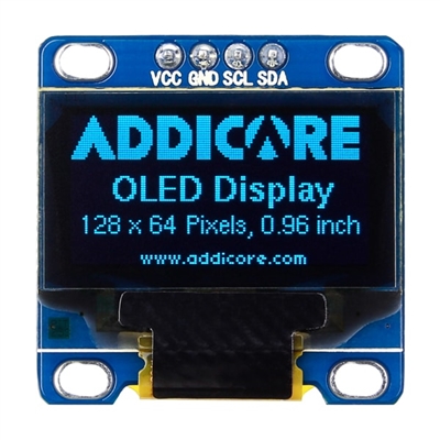
Connection with LCD
| OLED | OpenCM9.04 | etc |
|---|---|---|
| VCC | 3.3V | |
| GND | GND | |
| SCK | D24 | I2C2 |
| SDA | D25 | I2C2 |
Arduino code for LCD
Enable the DMP function of MPU6050 and output Roll / Pitch / Yaw value in serial every 50ms. The full source code is downloaded from the link below.
-
DownloadLibrary. Copy the following two libraries into the Document > Arduino > libraries folder and unzip them. https://github.com/ROBOTIS-GIT/OpenCM9.04/blob/master/arduino/opencm_arduino/examples/Adafruit_SSD1306/Adafruit_GFX_Library.zip
https://github.com/ROBOTIS-GIT/OpenCM9.04/blob/master/arduino/opencm_arduino/examples/Adafruit_SSD1306/Adafruit_SSD1306.zip -
DownloadSource Code. Extract downloaded source code and open the code from Arduino IDE with File > Open. https://github.com/ROBOTIS-GIT/OpenCM9.04/blob/master/arduino/opencm_arduino/examples/Adafruit_SSD1306/Exam_ssd1306_128x64_i2c.zip
/*********************************************************************
This is an example for our Monochrome OLEDs based on SSD1306 drivers

  Pick one up today in the adafruit shop!
  ------> http://www.adafruit.com/category/63_98

This example is for a 128x64 size display using I2C to communicate
3 pins are required to interface (2 I2C and one reset)

Adafruit invests time and resources providing this open source code,
please support Adafruit and open-source hardware by purchasing
products from Adafruit!

Written by Limor Fried/Ladyada  for Adafruit Industries.
BSD license, check license.txt for more information
All text above, and the splash screen must be included in any redistribution
*********************************************************************/

#include <SPI.h>
#include <Wire.h>
#include <Adafruit_GFX.h>
#include <Adafruit_SSD1306.h>

#define OLED_RESET 4
Adafruit_SSD1306 display(-1);

#define NUMFLAKES 10
#define XPOS 0
#define YPOS 1
#define DELTAY 2

#define LOGO16_GLCD_HEIGHT 16
#define LOGO16_GLCD_WIDTH  16
static const unsigned char PROGMEM logo16_glcd_bmp[] =
{ B00000000, B11000000,
  B00000001, B11000000,
  B00000001, B11000000,
  B00000011, B11100000,
  B11110011, B11100000,
  B11111110, B11111000,
  B01111110, B11111111,
  B00110011, B10011111,
  B00011111, B11111100,
  B00001101, B01110000,
  B00011011, B10100000,
  B00111111, B11100000,
  B00111111, B11110000,
  B01111100, B11110000,
  B01110000, B01110000,
  B00000000, B00110000 };

#if (SSD1306_LCDHEIGHT != 64)
#error("Height incorrect, please fix Adafruit_SSD1306.h!");
#endif

void setup()   {
  Serial.begin(9600);

  // by default, we'll generate the high voltage from the 3.3v line internally! (neat!)
  display.begin(SSD1306_SWITCHCAPVCC, 0x3C);  // initialize with the I2C addr 0x3D (for the 128x64)
  // init done

  // Show image buffer on the display hardware.
  // Since the buffer is intialized with an Adafruit splashscreen
  // internally, this will display the splashscreen.
  display.display();
  delay(2000);

  // Clear the buffer.
  display.clearDisplay();

  // draw a single pixel
  display.drawPixel(10, 10, WHITE);
  // Show the display buffer on the hardware.
  // NOTE: You _must_ call display after making any drawing commands
  // to make them visible on the display hardware!
  display.display();
  delay(2000);
  display.clearDisplay();

  // draw many lines
  testdrawline();
  display.display();
  delay(2000);
  display.clearDisplay();

  // draw rectangles
  testdrawrect();
  display.display();
  delay(2000);
  display.clearDisplay();

  // draw multiple rectangles
  testfillrect();
  display.display();
  delay(2000);
  display.clearDisplay();

  // draw mulitple circles
  testdrawcircle();
  display.display();
  delay(2000);
  display.clearDisplay();

  // draw a white circle, 10 pixel radius
  display.fillCircle(display.width()/2, display.height()/2, 10, WHITE);
  display.display();
  delay(2000);
  display.clearDisplay();

  testdrawroundrect();
  delay(2000);
  display.clearDisplay();

  testfillroundrect();
  delay(2000);
  display.clearDisplay();

  testdrawtriangle();
  delay(2000);
  display.clearDisplay();

  testfilltriangle();
  delay(2000);
  display.clearDisplay();

  // draw the first ~12 characters in the font
  testdrawchar();
  display.display();
  delay(2000);
  display.clearDisplay();

  // draw scrolling text
  testscrolltext();
  delay(2000);
  display.clearDisplay();

  // text display tests
  display.setTextSize(1);
  display.setTextColor(WHITE);
  display.setCursor(0,0);
  display.println("Hello, world!");
  display.setTextColor(BLACK, WHITE); // 'inverted' text
  display.println(3.141592);
  display.setTextSize(2);
  display.setTextColor(WHITE);
  display.print("0x"); display.println(0xDEADBEEF, HEX);
  display.display();
  delay(2000);
  display.clearDisplay();

  // miniature bitmap display
  display.drawBitmap(30, 16,  logo16_glcd_bmp, 16, 16, 1);
  display.display();
  delay(1);

  // invert the display
  display.invertDisplay(true);
  delay(1000);
  display.invertDisplay(false);
  delay(1000);
  display.clearDisplay();

  // draw a bitmap icon and 'animate' movement
  testdrawbitmap(logo16_glcd_bmp, LOGO16_GLCD_HEIGHT, LOGO16_GLCD_WIDTH);
}

void loop() {

}

void testdrawbitmap(const uint8_t *bitmap, uint8_t w, uint8_t h) {
  uint8_t icons[NUMFLAKES][3];

  // initialize
  for (uint8_t f=0; f< NUMFLAKES; f++) {
    icons[f][XPOS] = random(display.width());
    icons[f][YPOS] = 0;
    icons[f][DELTAY] = random(5) + 1;

    Serial.print("x: ");
    Serial.print(icons[f][XPOS], DEC);
    Serial.print(" y: ");
    Serial.print(icons[f][YPOS], DEC);
    Serial.print(" dy: ");
    Serial.println(icons[f][DELTAY], DEC);
  }

  while (1) {
    // draw each icon
    for (uint8_t f=0; f< NUMFLAKES; f++) {
      display.drawBitmap(icons[f][XPOS], icons[f][YPOS], bitmap, w, h, WHITE);
    }
    display.display();
    delay(200);

    // then erase it + move it
    for (uint8_t f=0; f< NUMFLAKES; f++) {
      display.drawBitmap(icons[f][XPOS], icons[f][YPOS], bitmap, w, h, BLACK);
      // move it
      icons[f][YPOS] += icons[f][DELTAY];
      // if its gone, reinit
      if (icons[f][YPOS] > display.height()) {
        icons[f][XPOS] = random(display.width());
        icons[f][YPOS] = 0;
        icons[f][DELTAY] = random(5) + 1;
      }
    }
   }
}

void testdrawchar(void) {
  display.setTextSize(1);
  display.setTextColor(WHITE);
  display.setCursor(0,0);

  for (uint8_t i=0; i < 168; i++) {
    if (i == '\n') continue;
    display.write(i);
    if ((i > 0) && (i % 21 == 0))
      display.println();
  }
  display.display();
  delay(1);
}

void testdrawcircle(void) {
  for (int16_t i=0; i<display.height(); i+=2) {
    display.drawCircle(display.width()/2, display.height()/2, i, WHITE);
    display.display();
    delay(1);
  }
}

void testfillrect(void) {
  uint8_t color = 1;
  for (int16_t i=0; i<display.height()/2; i+=3) {
    // alternate colors
    display.fillRect(i, i, display.width()-i*2, display.height()-i*2, color%2);
    display.display();
    delay(1);
    color++;
  }
}

void testdrawtriangle(void) {
  for (int16_t i=0; i<min(display.width(),display.height())/2; i+=5) {
    display.drawTriangle(display.width()/2, display.height()/2-i,
                     display.width()/2-i, display.height()/2+i,
                     display.width()/2+i, display.height()/2+i, WHITE);
    display.display();
    delay(1);
  }
}

void testfilltriangle(void) {
  uint8_t color = WHITE;
  for (int16_t i=min(display.width(),display.height())/2; i>0; i-=5) {
    display.fillTriangle(display.width()/2, display.height()/2-i,
                     display.width()/2-i, display.height()/2+i,
                     display.width()/2+i, display.height()/2+i, WHITE);
    if (color == WHITE) color = BLACK;
    else color = WHITE;
    display.display();
    delay(1);
  }
}

void testdrawroundrect(void) {
  for (int16_t i=0; i<display.height()/2-2; i+=2) {
    display.drawRoundRect(i, i, display.width()-2*i, display.height()-2*i, display.height()/4, WHITE);
    display.display();
    delay(1);
  }
}

void testfillroundrect(void) {
  uint8_t color = WHITE;
  for (int16_t i=0; i<display.height()/2-2; i+=2) {
    display.fillRoundRect(i, i, display.width()-2*i, display.height()-2*i, display.height()/4, color);
    if (color == WHITE) color = BLACK;
    else color = WHITE;
    display.display();
    delay(1);
  }
}

void testdrawrect(void) {
  for (int16_t i=0; i<display.height()/2; i+=2) {
    display.drawRect(i, i, display.width()-2*i, display.height()-2*i, WHITE);
    display.display();
    delay(1);
  }
}

void testdrawline() {
  for (int16_t i=0; i<display.width(); i+=4) {
    display.drawLine(0, 0, i, display.height()-1, WHITE);
    display.display();
    delay(1);
  }
  for (int16_t i=0; i<display.height(); i+=4) {
    display.drawLine(0, 0, display.width()-1, i, WHITE);
    display.display();
    delay(1);
  }
  delay(250);

  display.clearDisplay();
  for (int16_t i=0; i<display.width(); i+=4) {
    display.drawLine(0, display.height()-1, i, 0, WHITE);
    display.display();
    delay(1);
  }
  for (int16_t i=display.height()-1; i>=0; i-=4) {
    display.drawLine(0, display.height()-1, display.width()-1, i, WHITE);
    display.display();
    delay(1);
  }
  delay(250);

  display.clearDisplay();
  for (int16_t i=display.width()-1; i>=0; i-=4) {
    display.drawLine(display.width()-1, display.height()-1, i, 0, WHITE);
    display.display();
    delay(1);
  }
  for (int16_t i=display.height()-1; i>=0; i-=4) {
    display.drawLine(display.width()-1, display.height()-1, 0, i, WHITE);
    display.display();
    delay(1);
  }
  delay(250);

  display.clearDisplay();
  for (int16_t i=0; i<display.height(); i+=4) {
    display.drawLine(display.width()-1, 0, 0, i, WHITE);
    display.display();
    delay(1);
  }
  for (int16_t i=0; i<display.width(); i+=4) {
    display.drawLine(display.width()-1, 0, i, display.height()-1, WHITE);
    display.display();
    delay(1);
  }
  delay(250);
}

void testscrolltext(void) {
  display.setTextSize(2);
  display.setTextColor(WHITE);
  display.setCursor(10,0);
  display.clearDisplay();
  display.println("scroll");
  display.display();
  delay(1);

  display.startscrollright(0x00, 0x0F);
  delay(2000);
  display.stopscroll();
  delay(1000);
  display.startscrollleft(0x00, 0x0F);
  delay(2000);
  display.stopscroll();
  delay(1000);
  display.startscrolldiagright(0x00, 0x07);
  delay(2000);
  display.startscrolldiagleft(0x00, 0x07);
  delay(2000);
  display.stopscroll();
}
Video
Downloads
Download ZIPOpenCM 9.04 ManualDownload PDFPCB SchematicDownload PDFTop GerberDownload PDFBottom GerberDownload PDFGerberDownload Software LinkArduino IDEDownload Software LinkOpenCM IDE
References
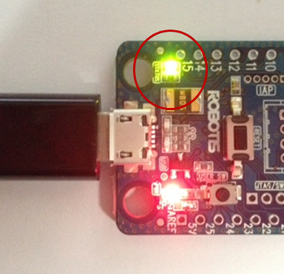
Recovery Mode
- If the board does not work due to corrupted firmware, you can force downloading default firmware from Roboplus Manager 1.0 / 2.0. Sketches also can be downloaded from Arduino IDE, OpenCM IDE.
-
Disconnect other power sources and devices from OpenCM9.04. While holding down the User Button of OpenCM9.04, connect the board directly to PC with USB cable.
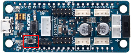
User Button
-
If you enter recovery mode as shown below, the green LED will be turned on. When download is completed normally, the board will be reset and the green LED is turned off.
NOTE R+Manager 2.0 Firmware Recovery.
Windows Driver Installation
Using DYNAMIXEL-X
To use ROBOTIS software (R+ Task, R+ Motion 및 R+ Manager) with DYNAMIXEL-X series, Configuring DYNAMIXEL Channle is required.
NOTE: Arduino IDE does not require DYNAMIXEL Channel configuration.
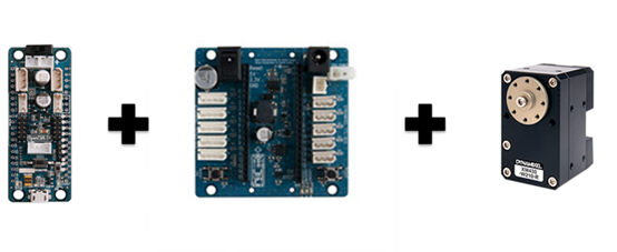
NOTE: With OpenCM485 EXP Board, DYNAMIXEL-X with 24V and RS-485 Communication Port can be used.
NOTE: If Molex type connectors are soldered on the OpenCM 9.04 (i.e, Type-B or Type-C), use JST-Molex convertable cable in order to wire DYNAMIXEL-X.
- A-Type: Soldering Required. See Connector Assembly(Type A)
- B-Type: Robot Cable-X3P (Convertible) and Robot Cable-XL320 (Convertible)
- C-Type: Robot Cable-XL320 (Convertible)
Configuring DYNAMIXEL Channel
Change DYNAMIXEL Channel’s item to use various DYNAMIXEL-X series.
NOTE:
- Keep a version of firmware up-to-date.
- If OpenCM485 board and OpenCM9.04 are connected, make sure to separate it before Firmware Update or Firmware Recovery.
-
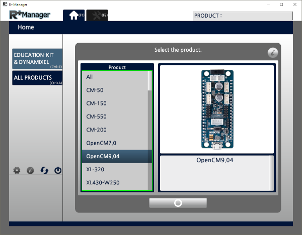
Open R+ Manager, and select OpenCM 9.04 in the Home tab.
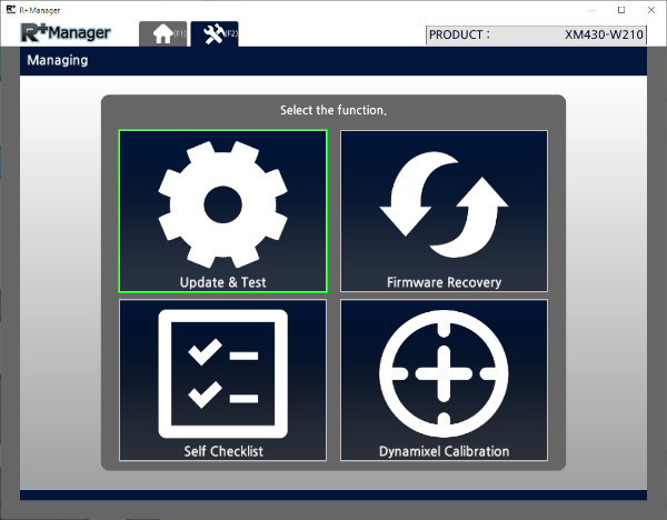
-
Select Update & Test.
-
When the control table appears, select an DYNAMIXEL’s bus channel on the list of Dynamixel Channel. For example, select EXP Board(X-Series) to use DYNAMIXEL-X series on the expansion board.
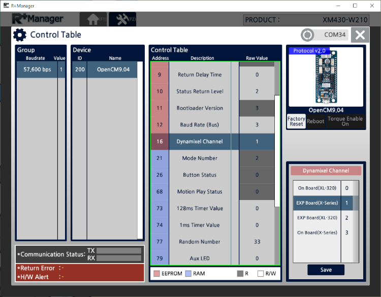
| Item | Description |
|---|---|
| On Board(XL-320) | Uses XL-320 only with the OpenCM 9.04 on ROBOTIS Software (R+ Motion and R+ Task) |
| EXP Board(X-Series) | Uses DYNAMIXEL-X series, XL-320 excluded, with the expantion board on ROBOTIS Software (R+ Motion and R+ Task) |
| EXP Board(XL-320) | Uses XL-320 only with the expantion board on ROBOTIS Software (R+ Motion and R+ Task) |
| On Board(X-Series) | Uses DYNAMIXEL-X series, XL-320 excluded, with the OpenCM 9.04 on ROBOTIS Software (R+ Motion and R+ Task) |
NOTE: After setup is complete, restart the OpenCM9.04 or the expansion board to activate DYNAMIXEL’s bus channel. Consequently, the DYNAMIXEL with the controller will properly work on the motion tool or with the motion file on the task program.
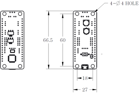
Dimension
Please also checkout ROBOTIS Download Center for software applications, 3D/2D CAD, and other useful resources!