
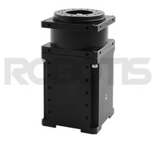
L54-30-S500-R
Specifications
| Item | Specifications |
|---|---|
| MCU | ARM CORTEX-M4 (168 [MHz], 32Bit) |
| Motor | BLDC |
| Baud Rate | 9,600 [bps] ~ 10.5 [Mbps] |
| Operating Modes | Torque Control Mode Velocity Control Mode Position Control Mode Extended Position Control Mode |
| Weight | 591 [g] |
| Dimensions (W x H x D) | 54 x 108 x 54 [mm] |
| Resolution | 361,384 [pulse/rev] |
| Gear Ratio | 501.923 : 1 |
| Backlash | < 6 [arcmin], 0.1 [°] |
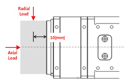
| Radial Load | 370 [N] (10 [mm] away from the horn) |
| Axial Load | 130 [N] |
| No Load Speed | 23.0 [rev/min] |
| No Load Current | 1.1 [A] |
1 Continuous Speed |
21.0 [rev/min] |
1 Continuous Torque |
5.4 [N.m] |
1 Continuous Current |
1.6 [A] |
| Output | 30 [W] |
| Operating Temperature | 5 ~ 55 [°C] |
| Input Voltage | 24.0 [V] |
| Command Signal | Digital Packet |
| Protocol Type | RS-485 Asynchronous Serial Communication (8bit, 1stop, No Parity) |
| Physical Connection | RS-485 Multidrop Bus |
| ID | 253 ID (0 ~ 252) |
| Standby Current | 80 [mA] |
1 These specifications are calculated based on the specifications of the core motor.
Please consult ROBOTIS for the long term use or special use, or else refer to the Performance Graph for general use.
![]()
DANGER
(Ignoring these warnings may cause serious injury or death)
- Never place items containing water, flammables/open flames, or solvents near the product.
- Never place fingers, arms, toes, and other body parts near product during operation.
- Cease operation and remove power from the product if the product begins to emit strange odors, noises, or smoke.
- Keep product out of reach of children.
- Check input polarity before installing or energizing wiring or cables.
![]()
CAUTION
(Ignoring these warnings may cause mild injury or damage to the product)
- Always comply with the product’s offical operating environment specifications including input voltage, current, and operating temperature.
- Do not insert blades or other sharp objects during product operation.
![]()
ATTENTION
(Ignoring these warnings may cause minor injury or damage to the product)
- Do not disassemble or modify the product.
- Do not drop the product or apply strong impacts.
- Do not connect or disconnect DYNAMIXEL cables while power is being supplied.
Performance Graph
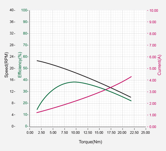
NOTE : The given Stall torque rating for a servo is different from it’s continuous output rating, and may also differ from it’s expected real world performance.
Stall torque is the maximum momentary torque output the servo is capable of, an is generally how RC servos are measured. The Performance graph, or N-T curve, from the above graph is measured under conditions simulating a gradually increasing load.
Generally, the Maximum Torque shown through Performance Graph testing is less than the maximum Stall Torque.
The actual real world performance of the servo will generally be closer to the performance graph measurements, not the rated stall torque.
CAUTION - When supplying power:
-
Do not connect or disconnect DYNAMIXEL actuator cables while power is being supplied.
-
For DYNAMIXEL PRO and DYNAMIXEL-P series servos, supply additional power through the 24V accessory power port.
Control Table
The Control Table is a data structure used by DYNAMIXEL actuators to manage the state of the device. Users can read data registers to get information about the status of the device with Read Instruction Packets, and modify data registers to control the device with Write Instruction Packets.
Control Table, Data, Address
The Control Table is a structure that consists of multiple Data fields to store status or to control the device. Users can check current status of the device by reading a specific Data from the Control Table with Read Instruction Packets. WRITE Instruction Packets enable users to control the device by changing specific Data in the Control Table. The Address is a unique value when accessing a specific Data in the Control Table with Instruction Packets. In order to read or write data, users must designate a specific Address in the Instruction Packet. Please refer to DYNAMIXEL Protocol 2.0 for more details about Instruction Packets.
NOTE : Two’s complement is applied for the negative value. For more information, please refer to Two’s complement from Wikipedia.
Area (EEPROM, RAM)
The Control Table is divided into 2 Areas. Data in the RAM Area is reset to initial values when the power is reset(Volatile). On the other hand, data in the EEPROM Area is maintained even when the device is powered off(Non-Volatile).
Data in the EEPROM Area can only be written to if Torque Enable(562) is cleared to ‘0’(Torque OFF).
Size
The Size of data varies from 1 ~ 4 bytes depend on their usage. Please check the size of data when updating the data with an Instruction Packet. For data larger than 2 bytes will be saved according to Little Endian.
Access
The Control Table has two different access properties. ‘RW’ property stands for read and write access permission while ‘R’ stands for read only access permission. Data with the read only property cannot be changed by the WRITE Instruction. Read only property(‘R’) is generally used for measuring and monitoring purpose, and read write property(‘RW’) is used for controlling device.
Initial Value
Each data in the Control Table is restored to initial values when the device is turned on. Default values in the EEPROM area are initial values of the device (factory default settings). If any values in the EEPROM area are modified by a user, modified values will be restored as initial values when the device is turned on. Initial Values in the RAM area are restored when the device is turned on.
Control Table of EEPROM Area
| Address | Size(Byte) | Data Name | Access | Initial Value |
Range | Unit |
|---|---|---|---|---|---|---|
| 0 | 2 | Model Number | R | 37,896 | - | - |
| 2 | 4 | Model Information | R | - | - | - |
| 6 | 1 | Firmware Version | R | - | - | - |
| 7 | 1 | ID | RW | 1 | 0 ~ 252 | - |
| 8 | 1 | Baud Rate | RW | 1 | 0 ~ 13 | - |
| 9 | 1 | Return Delay Time | RW | 250 | 0 ~ 255 | - |
| 11 | 1 | Operating Mode | RW | 3 | 0, 1, 3, 4 | - |
| 13 | 4 | Homing Offset | RW | 0 | -2,147,483,648 ~ 2,147,483,647 |
1 [pulse] |
| 17 | 4 | Moving Threshold | RW | 50 | 0 ~ 2,147,483,647 | 0.00199234 [rev/min] |
| 21 | 1 | Temperature Limit | RW | 80 | 0 ~ 100 | 1 [°C] |
| 22 | 2 | Max Voltage Limit | RW | 400 | 0 ~ 400 | 0.1 [V] |
| 24 | 2 | Min Voltage Limit | RW | 150 | 0 ~ 400 | 0.1 [V] |
| 26 | 4 | Acceleration Limit | RW | - | 0 ~ 2,147,483,647 | 58,000 [rev/min2] |
| 30 | 2 | Torque Limit | RW | 100 | 0 ~ 300 | 16.11328 [mA] |
| 32 | 4 | Velocity Limit | RW | 9,000 | 0 ~ 2,147,483,647 | 0.00199234 [rev/min] |
| 36 | 4 | Max Position Limit | RW | 180,692 | -2,147,483,648 ~ 2,147,483,647 |
1 [pulse] |
| 40 | 4 | Min Position Limit | RW | -180,692 | -2,147,483,648 ~ 2,147,483,647 |
1 [pulse] |
| 44 | 1 | External Port Mode 1 | RW | 0 | 0 ~ 3 | - |
| 45 | 1 | External Port Mode 2 | RW | 0 | 0 ~ 3 | - |
| 46 | 1 | External Port Mode 3 | RW | 0 | 0 ~ 3 | - |
| 47 | 1 | External Port Mode 4 | RW | 0 | 0 ~ 3 | - |
| 48 | 1 | Shutdown | RW | 58 | 0 ~ 255 | - |
| 49 | 2 | Indirect Address 1 | RW | 634 | 562 ~ 949 | - |
| 51 | 2 | Indirect Address 2 | RW | 635 | 562 ~ 949 | - |
| 53 | 2 | Indirect Address 3 | RW | 636 | 562 ~ 949 | - |
| … | 2 | Indirect Address N | RW | … | 562 ~ 949 | - |
| 559 | 2 | Indirect Address 256 | RW | 889 | 562 ~ 949 | - |
Control Table of RAM Area
| Address | Size(Byte) | Data Name | Access | Initial Value |
Range | Unit |
|---|---|---|---|---|---|---|
| 562 | 1 | Torque Enable | RW | 0 | 0 ~ 1 | - |
| 563 | 1 | LED Red | RW | 0 | 0 ~ 255 | - |
| 564 | 1 | LED Green | RW | 0 | 0 ~ 255 | - |
| 565 | 1 | LED Blue | RW | 0 | 0 ~ 255 | - |
| 586 | 2 | Velocity I Gain | RW | 16 | 0 ~ 65535 | - |
| 588 | 2 | Velocity P Gain | RW | 256 | 0 ~ 65535 | - |
| 594 | 2 | Position P Gain | RW | 32 | 0 ~ 65535 | - |
| 596 | 4 | Goal Position | RW | - | Min Position Limit(40) ~ Max Position Limit(36) |
1 [pulse] |
| 600 | 4 | Goal Velocity | RW | 0 | -Velocity Limit(32) ~ Velocity Limit(32) |
0.00199234 [rev/min] |
| 604 | 2 | Goal Torque | RW | 0 | -Torque Limit(30) ~ Torque Limit(30) |
16.11328 [mA] |
| 606 | 4 | Goal Acceleration | RW | 0 | 0 ~ Acceleration Limit(26) |
58,000 [rev/min2] |
| 610 | 1 | Moving | R | - | - | - |
| 611 | 4 | Present Position | R | - | - | 1 [pulse] |
| 615 | 4 | Present Velocity | R | - | - | 0.00199234 [rev/min] |
| 621 | 2 | Present Current | R | - | - | 16.11328 [mA] |
| 623 | 2 | Present Input Voltage | R | - | - | 0.1 [V] |
| 625 | 1 | Present Temperature | R | - | - | 1 [°C] |
| 626 | 2 | External Port Data 1 | R/RW | 0 | 0 ~ 4,095 | - |
| 628 | 2 | External Port Data 2 | R/RW | 0 | 0 ~ 4,095 | - |
| 630 | 2 | External Port Data 3 | R/RW | 0 | 0 ~ 4,095 | - |
| 632 | 2 | External Port Data 4 | R/RW | 0 | 0 ~ 4,095 | - |
| 634 | 1 | Indirect Data 1 | RW | 0 | 0 ~ 255 | - |
| 635 | 1 | Indirect Data 2 | RW | 0 | 0 ~ 255 | - |
| 636 | 1 | Indirect Data 3 | RW | 0 | 0 ~ 255 | - |
| … | 1 | Indirect Data N | RW | 0 | 0 ~ 255 | - |
| 889 | 1 | Indirect Data 256 | RW | 0 | 0 ~ 255 | - |
| 890 | 1 | Registered Instruction | R | 0 | - | - |
| 891 | 1 | Status Return Level | RW | 2 | 0 ~ 2 | - |
| 892 | 1 | Hardware Error Status | R | 0 | - | - |
Control Table Description
CAUTION : Data in the EEPROM Area can only be written when the value of Torque Enable(562) is cleared to ‘0’.
Model Number(0)
This address stores model number of DYNAMIXEL.
| Model Name | Model Number |
|---|---|
| L54-30-S500-R | 37896 (0x9408) |
Firmware Version(6)
This address stores firmware version of DYNAMIXEL.
ID(7)
The ID is a unique value in the network to identify each DYNAMIXEL with an Instruction Packet. 0~252 (0xFC) values can be used as an ID, and 254(0xFE) is occupied as a broadcast ID. The Broadcast ID(254, 0xFE) can send an Instruction Packet to all connected DYNAMIXEL simultaneously.
NOTE : Please avoid using an identical ID for multiple DYNAMIXEL. You may face communication failure or may not be able to detect DYNAMIXEL with an identical ID.
NOTE : If the Instruction Packet ID is set to the Broadcast ID(0xFE), Status Packets will not be returned for READ or WRITE Instructions regardless of the set value of Stuatus Return Level (68). For more details, please refer to the Status Packet section for DYNAMIXEL Protocol 2.0
Baud Rate(8)
Baud Rate determines serial communication speed between a controller and DYNAMIXEL.
| Value | Baud Rate |
|---|---|
| 8 | 10.5M |
| 7 | 4.5M |
| 6 | 4M |
| 5 | 3M |
| 4 | 2M |
| 3 | 1M |
| 2 | 115,200 |
| 1(Default) | 57,600 |
| 0 | 9,600 |
NOTE : Less than 3% of the baud rate error margin will not affect to UART communication.
NOTE : For the stable communication with higher Baudrate, configure USB Latency value to the lower.
USB Latency Setting
Return Delay Time(9)
If the DYNAMIXEL receives an Instruction Packet, it will return the Status Packet after the time of the set Return Delay Time(9).
Note that the range of values is 0 to 254 (0XFE) and its unit is 2 [μsec]. For instance, if the Return Delay Time(9) is set to ‘10’, the Status Packet will be returned after 20[μsec] when the Instruction Packet is received.
| Unit | Value Range | Description |
|---|---|---|
| 2[μsec] | 0 ~ 254 | Default value ‘250’(500[μsec]) Maximum value: ‘508’[μsec] |
Operating Mode(11)
| Value | Operating Mode | Description |
|---|---|---|
| 0 | Torque Control Mode | This mode only controls Torque. Speed and Position will not be controlled. |
| 1 | Velocity Control Mode | This mode controls Velocity and Torque. Position will not be controlled. |
| 3(Default) | Position Control Mode | This mode controls Position, Velocity and Torque. |
| 4 | Extended Position Control Mode | This mode controls Position, Velocity and Torque. Multi-turn is enabled. |
NOTE : Present Position(611) represents a 4 byte continuous range from -2,147,483,648 to 2,147,483,647 when Torque is turned off regardless of Operating Mode(11).
However, Present Position(611) will be reset to an absolute position value within one full rotation in the following cases:
- When the Operating Mode(11) is changed to Position Control Mode.
- When torque is turned on in Position Control Mode.
- When the actuator is turned on or when rebooted using a Reboot Instruction.
Note that a Present Position(611) value that has been reset to the absolute value within a single rotation will still be affected by the configured Homing Offset(13) value.
Homing Offset(13)
Users can adjust the Home position by setting Homing Offset(13). The Homing Offset value is added to the Present Position(611). Present Position(611) = Actual Position + Homing Offset(13).
| Value Range |
|---|
| -2,147,483,648 ~ 2,147,483,647 |
Moving Threshold(17)
This value helps to determine whether the DYNAMIXEL is in motion or not.
If Present Velocity(615) is bigger than Moving Threshold(17) value, Moving(610) is set to ‘1’. Otherwise Moving(610) is cleared to ‘0’.
This value determines whether DYNAMIXEL is in motion or not.
| Value Range |
|---|
| 0 ~ 2,147,483,647 |
Temperature Limit(21)
This value limits operating temperature.
When the Present Temperature(625) that indicates internal temperature of DYNAMIXEL is greater than the Temperature Limit(21), the Overheating Error Bit(Bit 2) in the Hardware Error Status(892) will be set.
If Overheating Error Bit(Bit 2) is configured in the Shutdown(48) when Overheating Error occurs, Torque Enable(562) is cleared to ‘0’ and Torque will be disabled.
For more details, please refer to the Shutdown(48) section.
| Unit | Value Range | Description |
|---|---|---|
| About 1° | 0 ~ 100 | 0 ~ 100° |
CAUTION : Do not set the temperature higher than the default value. When the temperature alarm shutdown occurs, wait for 20 minutes to cool the temperature before reuse. Keep using the product with high temperature can cause severe damage to DYNAMIXEL.
Min/Max Voltage Limit(22, 24)
These values are maximum and minimum operating voltages.
When present input voltage acquired from Present Input Voltage(623) exceeds the range of Max Voltage Limit(36) and Min Voltage Limit(40), Input Voltage Error Bit(Bit 0) in the Hardware Error Status(892) will be set to ‘1’.
If Input Voltage Error Bit(Bit 0) is configured in the Shutdown(48) when Input Voltage Error occurs, Torque Enable(562) is cleared to ‘0’ and Torque will be disabled.
For more details, please refer to the Shutdown(48) section.
| Unit | Value Range | Description |
|---|---|---|
| About 0.1V | 0 ~ 400 | 0 ~ 40.0V |
Acceleration Limit(26)
This data indicates maximum value of Goal Acceleration(606).
Goal Acceleration(606) can’t be configured with any values exceeding the Acceleration Limit(26).
Attempting to write an exceeding value will result transmitting Data Limit Error(0x06) in the Error field of the Status Packet.
Goal Acceleration(606) is used in all operating mode except Current(Torque) Control Mode in order to generate a desired trajectory.
| Value Range |
|---|
| 0 ~ 2,147,483,647 |
Torque Limit(30)
This value indicates torque limit. Goal Torque(604) can’t exceed this value.
Attempting to write an exceeding value will fail and result in receiving a Limit Error Bit from the Status Packet.
| Value Range |
|---|
| 0 ~ 32,767 |
Velocity Limit(32)
This value indicates velocity limit.
The Goal Velocity(600) can’t exceed this value.
Attempting to write an exceeding value will fail and result in receiving a Limit Error Bit from the Status Packet.
| Value Range |
|---|
| 0 ~ 2,147,483,647 |
Min/Max Position Limit(36, 40)
These values limit maximum and minimum desired positions.
The Goal Position(596) can’t exceed these values.
Attempting to write an exceeding value will fail and result in receiving a Limit Error Bit from the Status Packet.
The position value range is -2,147,483,648 ~ 2,147,483,647 while the position limit value ranges are vary by products, so please refer to below table.
In Extended Position Control Mode, these limits will be ignored.
| Model Name | Limit Value Range |
|---|---|
| H54-200-S500-R H54-100-S500-R |
-250,961 ~ 250,961 |
| H42-20-S300-R | -151,875 ~ 151,875 |
| M54-60-S250-R M54-40-S250-R |
-125,708 ~ 125,708 |
| M42-10-S260-R | -131,593 ~ 131,593 |
| L54-50-S290-R | -103,846 ~ 103,846 |
| L54-50-S500-R L54-30-S500-R |
-180,692 ~ 180,692 |
| L54-30-S400-R | -144,197 ~ 144,197 |
External Port Mode, External Port Data
External ports that can be used for various purposes are provided.
The property of each port is configured by the External Port Mode (44, 45, 46, 47) and data of external port is controlled by the External Port Data(626, 628, 630, 632).
| External Port Mode | Mode | Description |
|---|---|---|
| 0 | AI(Analogue Input) | Converts External Port signal to 12[bit] digital value |
| 1 | DO_PP(Digital Output Push-Pull) | Use External Port as a digital output port(3.3V level) |
| 2 | DI_PU(Digital Input Pull-Up) | Use External Port as a digital input port Floating connection will be considered as ‘1’ |
| 3(default) | DI_PD(Digital Input Pull-Down) | Use External Port as a digital input port Floating connection will be considered as ‘0’ |
| External Port Mode | Access | Details | Electrical Characteristics |
|---|---|---|---|
| Common | - | - | 0 ~ 3.3[V], 0 ~ 5[mA] VESD(HBM) : 2[kV] |
| 0(AI) | Read | Converts External Port signal to digital value External Data = signal x (4,095 / 3.3) |
Resolution : 12[bit] (0 ~ 4,095) |
| 1(DO_PP) | Write | 0 : Set External Port output to 0[V] 1 : Set External Port output to 3.3[V] |
Output High level(VOH) : 2.4 [V] (min) Output Low level(VOL) : 0.5 [V] (max) |
| 2(DI_PU) 3 (DI_PD) |
Read | 0: External Port input is 0[V] 1 : External Port input is 3.3[V] |
Input High level(VIH) : 2.3 [V] (min) Input Low level(VIL) : 1.0 [V] (max) Pull-Up/Down : 40 [kΩ] (typ) |
※ VESD(HBM) : ESD(Electrostatic Discharge) Voltage(human body model)
The External Port is not electrically insulated, therefore, abide by the electrical specifications.
If the electrical specification is exceeded or there is a problem with the signal connection, special caution is required because DYNAMIXEL can be damaged.
- Be careful not to cause electric shock by static electricity (ESD), short circuit, open circuit.
- Be careful not to let water or dust get into the External Port connector.
- If you are not using the External Port, remove the cable.
- To connect or disconnect the External Port, proceed with power off.
- Do not connect the GNDext pin of External Port directly to the GND pin of DYNAMIXEL connector. Noise from power may affect on the External Port.
External expansion port location and pin function
Remove bolts and cover plate to reveal External Port connector.
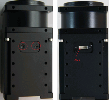
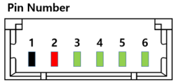
| Pin 1 | Pin 2 | Pin 3 | Pin 4 | Pin 5 | Pin 6 |
|---|---|---|---|---|---|
| GND | 3.3V | PORT1 | PORT2 | PORT3 | PORT4 |
Shutdown(48)
The DYNAMIXEL can protect itself by detecting dangerous situations that could occur during the operation. Each Bit is inclusively processed with the ‘OR’ logic, therefore, multiple options can be generated. For instance, when ‘0x05’ (binary : 00000101) is defined in Shutdown(48), DYNAMIXEL can detect both Input Voltage Error(binary : 00000001) and Overheating Error(binary : 00000100). If those errors are detected, Torque Enable(562) is cleared to ‘0’ and the motor’s output becomes 0 [%].
REBOOT is the only method to reset Torque Enable(562) to ‘1’(Torque ON) after the shutdown.
Check Alert Bit(0x80) in an error field of Status Packet or a present status via Hardware Error Status(892). The followings are detectable situations.
| Bit | Item | Description |
|---|---|---|
| Bit 7 | - | Not used, always ‘0’ |
| Bit 6 | - | Not used, always ‘0’ |
| Bit 5 | Overload Error(Default) | Detects that persistent load exceeds maximum output |
| Bit 4 | Electrical Shock Error(Default) | Detects electric shock on the circuit or insufficient power to operate the motor |
| Bit 3 | Motor Encoder Error(Default) | Detects malfunction of the motor encoder |
| Bit 2 | Overheating Error | Detects that internal temperature exceeds the configured operating temperature |
| Bit 1 | Motor Hall Sensor Error(Default) | Detects that Motor hall sensor value exceeds normal range |
| Bit 0 | Input Voltage Error | Detects that input voltage exceeds the configured operating voltage |
NOTE :
- If Shutdown occurs, Dynamic brake will be activated.
- If Shutdown occurs, LED will flicker every second.
- If Shutdown occurs, reboot the device.
- H/W REBOOT : Turn off and turn on the power again
- S/W REBOOT : Transmit REBOOT Instruction (For more details, refer to the Reboot section of e-Manual.)
Indirect Address, Indirect Data
Indirect Address and Indirect Data are useful when accessing two remote addresses in the Control Table as sequential addresses. Sequential addresses increase Instruction Packet efficiency. Addresses that can be defined as Indirect Address is limited to RAM area(Address 562 ~ 892). If specific address is allocated to Indirect Address, Indirect Address inherits features and properties of the Data from the specific Address. Property includes Size(Byte length), value range, and Access property(Read Only, Read/Write). For instance, if address 563(LED Red) is allocated to Indirect Address 1(49), Indirect Data 1(634) will have the exactly same value of LED Red(563).
Example 1
Allocating 1 byte LED(563) to Indirect Data 1(634).
- Indirect Address 1(49) : change the value to ‘563’ which is the address of LED Red.
- Set Indirect Data 1(634) to ‘1’ : LED Red(563) also becomes ‘1’ and Red LED will be turned on.
- Set Indirect Data 1(634) to ‘0’ : LED Red(563) also becomes ‘0’ and Red LED will be turned off.
Example 2
Allocating Size 4 byte Goal Position(596) to Indirect Data 2(635), 4 sequential bytes have to be allocated.
- Indirect Address 2(51) : change the value to ‘596’ which is the first address of Goal Position.
- Indirect Address 3(53) : change the value to ‘597’ which is the second address of Goal Position.
- Indirect Address 4(55) : change the value to ‘598’ which is the third address of Goal Position.
- Indirect Address 5(57) : change the value to ‘599’ which is the fourth address of Goal Position.
- Set 4 byte value 305,419,896(0x12345678) to Indirect Data 2 : Goal Position(596) also becomes 305,419,896(0x12345678) as below.
| Indirect Data Address | Goal Position Address | Saved HEX Value |
|---|---|---|
| 635 | 596 | 0x78 |
| 636 | 597 | 0x56 |
| 637 | 598 | 0x34 |
| 638 | 599 | 0x12 |
NOTE : In order to allocate Data in the Control Table longer than 2[byte] to Indirect Address, all address must be allocated to Indirect Address like the above Example 2.
NOTE : Indirect Address 29 ~ 56 and Indirect Data 29 ~ 56 can only be accessed with Protocol 2.0.
Torque Enable(562)
Torque Enable(64) determines Torque ON/OFF. Writing ‘1’ to Torque Enable’s address will turn on the Torque and all Data in the EEPROM area will be locked.
| Value | Description |
|---|---|
| 0(Default) | Torque Off |
| 1 | Torque On and lock EEPROM area |
NOTE : Present Position(611) can be reset when Operating Mode(11) and Torque Enable(562) are updated. For more details, please refer to the Homing Offset(13) and Present Position(611).
RGB LED(563)
Controls the RGB LED on DYNAMIXEL PRO.
| Address | Color | Range |
|---|---|---|
| 563 | Red | 0 ~ 255 |
| 564 | Green | 0 ~ 255 |
| 565 | Blue | 0 ~ 255 |
NOTE : The LED indicates present status of the device.
| Status | LED Representation |
|---|---|
| Booting | LED flickers once |
Velocity PI Gain(586, 588)
These values indicate P and I Gains of Velocity Control Mode. The I Gain includes sampling time. Velocity P Gain of DYNAMIXEL’s internal controller is abbreviated to KVP and Velocity I Gain is abbreviated to KVI.
| Gain Value Range |
|---|
| 0 ~ 32,767 |
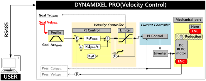
NOTE : KPA stands for Anti-windup Gain that cannot be modified by users. For more details about the PID controller, please refer to the PID Controller at wikipedia.
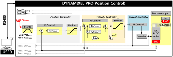
Position P Gain(594)
This P Gain is used in Position Control Mode. Below figure is a block diagram describing the Position Control Mode. The Position Controller is cascaded with the Velocity Controller. KPP stands for Position P Gain.
| Gain Value Range |
|---|
| 0 ~ 32,767 |
Goal Position(596), Present Position(611)
Desired position can be set with Goal Position(596). This value can’t be smaller than the Min Position Limit(40) or larger than Max Position Limit(36).
| Model | Angle Range | Position Range | Description |
|---|---|---|---|
| H54-200-S500-R H54-100-S500-R |
-179.999 ° ~ 179.999 ° | -250,961 ~ 250,961 | 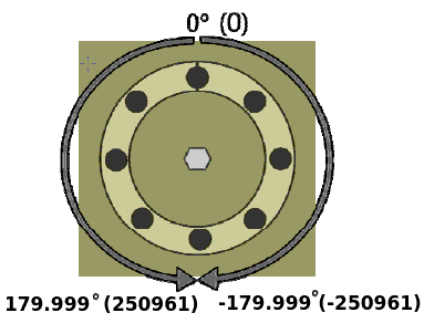 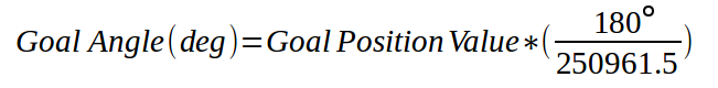 |
| H42-20-S300-R | -180° ~ 180 ° | -151,875 ~ 151,875 | 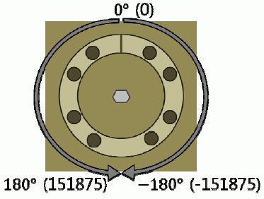 |
NOTE : Present Position(611) represents a 4 byte continuous range from -2,147,483,648 to 2,147,483,647 when Torque is turned off regardless of Operating Mode(11).
However, Present Position(611) will be reset to an absolute position value within one full rotation in the following cases:
- When the Operating Mode(11) is changed to Position Control Mode.
- When torque is turned on in Position Control Mode.
- When the actuator is turned on or when rebooted using a Reboot Instruction.
Note that a Present Position(611) value that has been reset to the absolute value within a single rotation will still be affected by the configured Homing Offset(13) value.
Goal Velocity(600)
Goal Velocity(600) can be used to set a desired velocity and this value cannot exceed Velocity Limit (32). In case of Position Control Mode or Extended Position Control Mode, Goal Velocity will be used to limit the velocity. However, if Goal Velocity is set to ‘0’, Velocity Limit(32) will be used to limit the velocity. (Please refer to the block diagram of Position P Gain) The Goal Velocity stands for the RPM of the motor before the reduction gears and output RPM after the reduction gears can be calculated using below scale factor. Output RPM = Goal Velocity * Scale Factor
| Model | Scale Factor(RPM) |
|---|---|
| H54-200-S500-R H54-100-S500-R |
0.00199234 |
| H42-20-S300-R | 0.00329218 |
| M54-60-S250-R M54-40-S250-R |
0.00397746 |
| M42-10-S260-R | 0.00389076 |
| L54-50-S290-R | 0.00346667 |
| L54-50-S500-R L54-30-S500-R |
0.00199234 |
| L54-30-S400-R | 0.00249657 |
Goal Torque(604)
Goal torque (604) can be used to set a desired torque and this value cannot exceed Torque Limit(30). When the Operating Mode(11) is set other than Torque Control Mode, Goal Torque will be used to limit the torque. However, if Goal Torque is set to ‘0’, Torque Limit(30) will be used to limit the torque. (Please refer to the block diagram of Position Gain or Velocity Gain) The relationship between torque, current, and goal torque is shown below.
| Model | Formula |
|---|---|
| PRO 54 | A = C x 33,000 ÷ 2,048 A = Current on Motor Coil[mA] C = Present Current(621) or Goal Torque(604) |
| PRO 42 | A = C x 8,250 ÷ 2,048 A = Current on Motor Coil[mA] C = Present Current(621) or Goal Torque(604) |
Goal Acceleration(606)
Goal Acceleration(606) can be used to set a desired acceleration. This value is used in Velocity Control Mode, Position Control Mode and Extended Position Control Mode. The profile control will be enabled when both Goal Acceleration(606) and Goal Velocity(600) are not ‘0’. Please refer to the Goal Velocity(600) for RPM conversion constant.
| Value Range | Unit |
|---|---|
| -2,147,483,647 ~ 2,147,483,647 | 58,000 RPM2 @ Core Motor |
Moving(610)
This value indicates whether DYNAMIXEL PRO is in motion or not. If absolute value of Present Velocity(615) is greater than Moving Threshold(17), Moving(610) is set to ‘1’. Otherwise, it will be cleared to ‘0’. However, this value will always be set to ‘1’ regardless of Present Velocity(615) while Profile is in progress with Goal Position(596) instruction.
| Value | Description |
|---|---|
| 0 | Movement is not detected |
| 1 | Movement is detected, or Profile is in progress(Goal Position(596) instruction is being processed) |
Present Velocity(615)
This value indicates present Velocity. For more details, please refer to the Goal Velocity(600).
Present Current(621)
This value indicates present Current. For more details, please refer to the Goal Torque(604).
Present Input Voltage(623)
This value indicates present voltage that is being supplied. For more details, please refer to the Min/Max Voltage Limit(24, 22).
Present Temperature(625)
This value indicates present internal Temperature. For more details, please refer to the Temperature Limit(21).
Registered Instruction(890)
Indicates whether the Write Instruction is registered by Reg Write Instruction
| Value | Description |
|---|---|
| 0 | No instruction registered by REG_WRITE. |
| 1 | Instruction registered by REG_WRITE exists. |
NOTE : If ACTION instruction is executed, the Registered Instruction (69) will be changed to 0.
Status Return Level(891)
The Stuatus Return Level (68) decides how to return Status Packet when DYNAMIXEL receives an Instruction Packet.
| Value | Responding Instructions | Description |
|---|---|---|
| 0 | PING Instruction | Returns the Status Packet for PING Instruction only |
| 1 | PING Instruction READ Instruction |
Returns the Status Packet for PING and READ Instruction |
| 2 | All Instructions | Returns the Status Packet for all Instructions |
NOTE : If the Instruction Packet ID is set to the Broadcast ID(0xFE), Status Packet will not be returned for READ or WRITE Instructions regardless of Stuatus Return Level (68). For more details, please refer to the Status Packet section for DYNAMIXEL Protocol 2.0.
Hardware Error Status(892)
This value indicates hardware error status. For more details, please refer to the Shutdown(48).
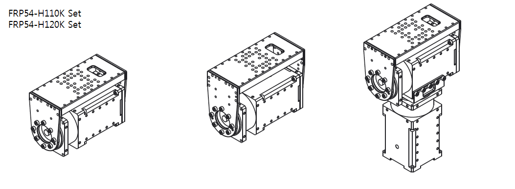
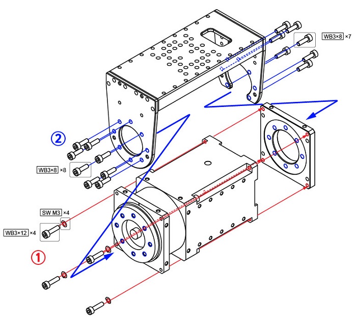
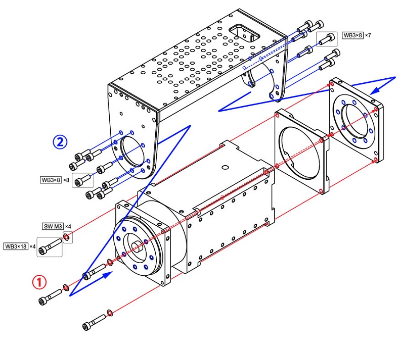
How to Assemble
Option Frame Assembly
-
FRP54-H110K, FRP54-H120K Set
-
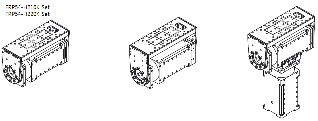
FRP54-H210K, FRP54-H220K Set
Maintenance
Reference
NOTE
Compatibility Guide
Harness Compatibility
Certifications
Please inquire us for information regarding unlisted certifications.
FCC
Note: This equipment has been tested and found to comply with the limits for a Class A digital device, pursuant to part 15 of the FCC Rules. These limits are designed to provide reasonable protection against harmful interference when the equipment is operated in a commercial environment. This equipment generates, uses, and can radiate radio frequency energy and, if not installed and used in accordance with the instruction manual, may cause harmful interference to radio communications. Operation of this equipment in a residential area is likely to cause harmful interference in which case the user will be required to correct the interference at his own expense.
WARNING
Any changes or modifications not expressly approved by the manufacturer could void the user’s authority to operate
the equipment.
Connector Information
| Item | RS-485 | Power | External Port |
|---|---|---|---|
| Pinout | 1 GND2 VDD3 DATA+4 DATA- |
1 GND2 VDD |
1 GND2 VDD3 PORT 14 PORT 25 PORT 36 PORT 4 |
| Diagram |  |
 |
 |
| Housing | 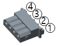 MOLEX 50-37-5043 |
 MOLEX 39-01-2020 |
 MOLEX 51021-0600 |
| PCB Header | 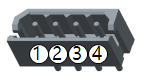 MOLEX 22-03-5045 |
 MOLEX 39-28-1023 |
 MOLEX 53047-0610 |
| Crimp Terminal | MOLEX 08-70-1039 | MOLEX 39-00-0038 | MOLEX 50079-8100 |
| Wire Gauge for DYNAMIXEL | 21 AWG | 20 AWG | 21 AWG |
WARNING: To enhance user safety and to prevent proprietary risk or damage, be sure to check the pinout installed on DYNAMIXEL and the board. The Pinout of DYNAMIXEL may differ depending on a manufacturer of connector.
WARNING: Before operating DYNAMIXEL PRO and DYNAMIXEL-P, please supply power through 24V power port.
Communication Circuit
To control DYNAMIXEL PRO with a custom made Main Controller, the signal of Main Controller UART should be converted into RS-485 signal. The following is a recommended conversion circuit diagram.
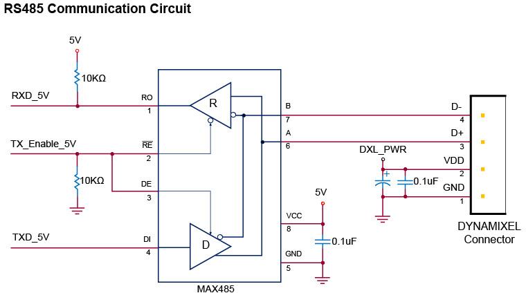
NOTE: Above circuit is designed for 5V or 5V tolerant MCU. Otherwise, use a Level Shifter to match the voltage of MCU.
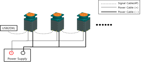
The power is supplied via Pin1(-) and Pin2(+) of DYNAMIXEL. (The above circuit is built into DYNAMIXEL-only controllers)
In the above circuit diagram, the direction of data signal of TxD and RxD in the TTL Level is determined according to the level of TX_Enable_5V as follows:
- If
TX_Enable_5V= High : TheTXD_5Vsignal is transferred toD+andD-. - If
TX_Enable_5V= Low : TheD+andD-signals are transferred toRXD_5V.
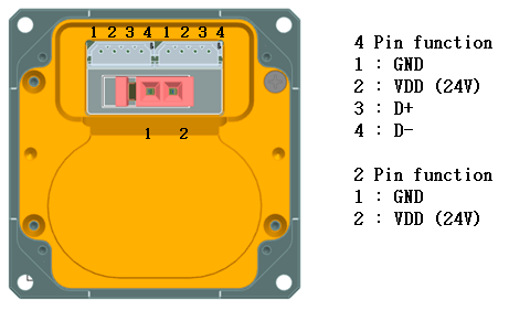
Pin Arrangement
Connector pin arrangement is shown below.
DYNAMIXEL PRO has two 4-pin connectors arranged in pin-2-pin configuration.
In this arrangement there’s no priority in the connector order and DYNAMIXEL PRO can be driven like the MX-series.
Additionally there is a 2-pin connector dedicated for power input for high-current operations.
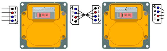
WARNING : When wiring please pay attention to the pin arrangement. Incorrectly connected DYNAMIXEL PRO may be damaged severely.
Drawings
Please also checkout ROBOTIS Download Center for software applications, 3D/2D CAD, and other useful resources!