
Introduction
Motion is a necessary set of position and speed data for motors, which eventually becomes a valid movement for a robot.
In order to make the robot move, the correct Motion project file must be edited and downloaded to the robot.
The Motion project file has an .mtnx extension, and is shown on the PC as the icon below.

- What is the relationship between a Motion file and Task file?
The Task file is a program code which defines the logics on how the robot will think and move. The Motion file is the data which defines the movements based on the decisions made from the Task file.
If the robot only performs simple movements, its Task file will not require any Motion file. But if precise movement is required, such as a dance choreography, it will be much more efficient to use the Motion file.
(If the Motion file is used in the Task code, the Motion file must be downloaded to the robot as well)
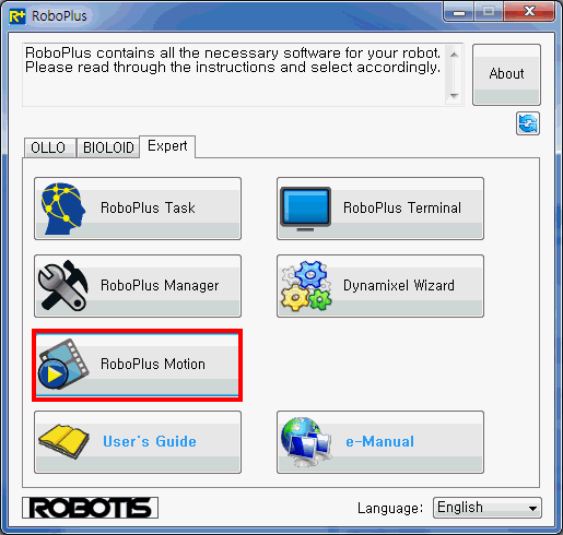
Software Install
![]()
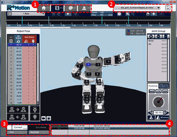
Menu
-
Editing tab per phase
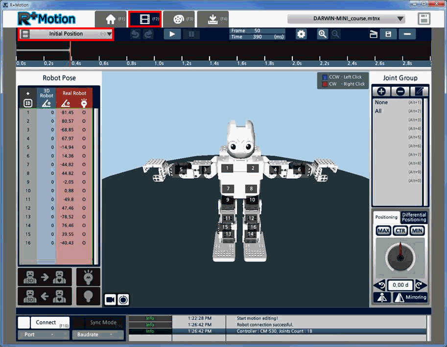
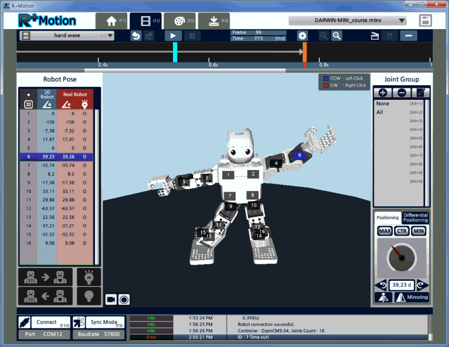
Motion editing is divided into the following 4 phases, which is performed in the sequential order. Each tab menu can be accessed through shortcut keys F1~F4 as well.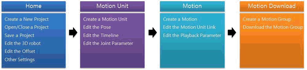
-
Quick Menu
Open a project or save the current project without having to move to the Home tab. -
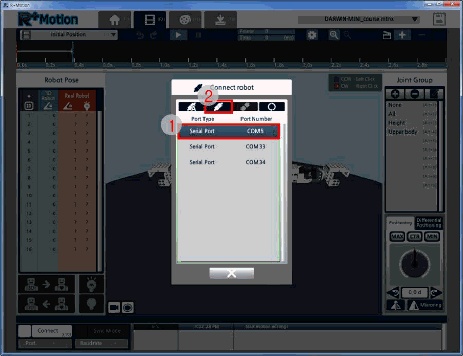
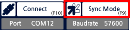
Robot Connection Menu
When the “Connect” button is clicked and the Connect Robot window is activated, you may select the port number to connect to your robot.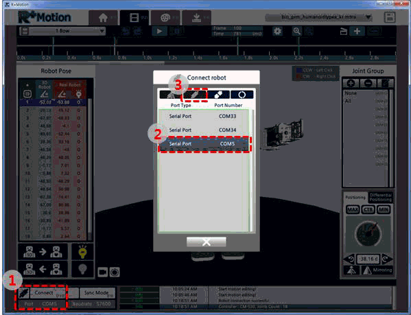
-
Log window
The log window shows Info or Error that are notified during the motion editing process. As seen in the image below, the 1) Log Level, 2) Log Time, and 3) Message is shown.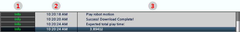
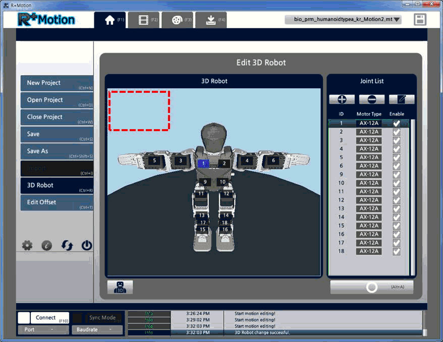
3D Robot and Actual Robot
The 3D robot acts as an avatar of the actual robot. Even when an actual robot is not present, the 3D robot can be used to edit or playback motions. When the actual robot is connected, and Sync Mode is turned on, the 3D robot can be used as an interface to control the actual robot.
When creating a new motion project, users can select a 3D model to open, based on the product lineup provided in the software. The 3D robot initially selected can be edited after creating the motion project.
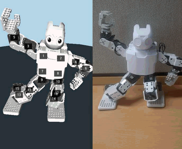
If the user is using a user created robot apart from the provided 3D models, a customized robot can be created by adding descriptions on each motor (image below).
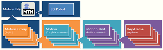
Motion Data
The data structure of a motion file is described in the image below.
-
Key-Frame
This is a similar concept as the Motion Step in the previous Motion software.
It is a combination of 1) pose and 2) time on timeline, to express WHAT (pose) to show WHEN (time). For example, if a ‘Hurrah’ pose is saved as a Key-Frame on 1.5 sec on the timeline, the robot will start to move into the ‘Hurrah’ pose as the timeline approaches 1.5 sec.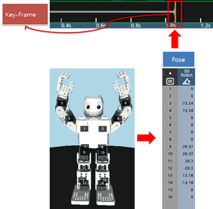
-
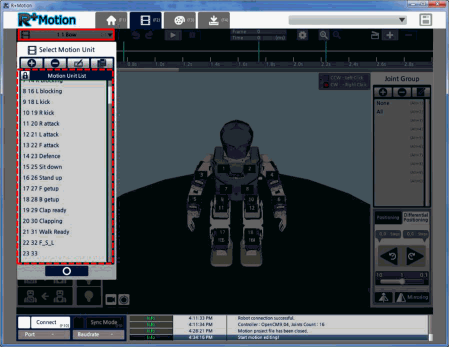
Motion Unit
This is a similar concept as the Motion Page in the previous Motion software. It is a group of Key-Frames placed on the timeline, to show a continuous movement. As seen on the image below the ‘Clap’ motion unit has the “hands spread” Key-Frame on 0.5 sec, and “hands closed” Key-Frame on 1 sec. The continuous movement (Motion Unit) will be a clapping motion.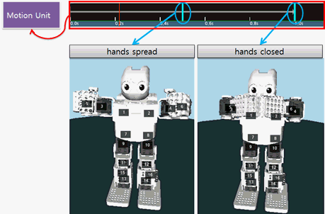
-
Motion
This is a similar concept as the Page Link in the previous Motion software. Motion is a group of Motion Units to express long movements, such a dancing motions.
As seen in the image below, the “Taekwon Dance” Motion is a link (group) of the Motion Units “Left Jab”, “Left turn”, “Right Attack 1”, and “Right Uppercut”.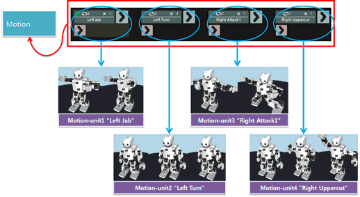
Green Arrowis the button to insert another Motion Unit to be played back after the current Motion Unit.Pink Arrowis the button to insert a Exit Motion Unit that is played when a current Motion Unit is interrupted by a particular command, parameter or etc.- More information is available at Edit Motion
-
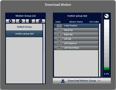
Motion Group
File size is unlimited in Motion 2.0. So, when downloading to the robot, users must select the specific Motions they want to download to the robot, while checking the space available on the robot.
The list comprised of the selected Motions is called the “Motion Group”. The bar on the right displays the amount of space the Motion Group will take up on the robot’s controller.
On the image below, the “Demonstration Set” Motion Group has 4 Motions in the list, and takes up 13.4% of the controller’s space.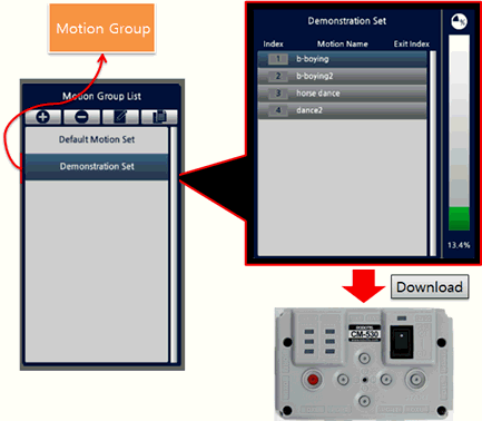
-
3D Robot
The 3D robot is the output when motion data is put in. It is also active even when an actual robot is not connected,so users can easily check and playback the motion they are creating.
Users are required to select a 3D robot when creating a motion file, and may also use the “Change 3D Robot” menu.
The image below is an example showing the same motion data opened on different 3D robots.
Editing Timeline
In the previous version of Motion software, the Motion Page was used to express a robot’s motion. In Motion 2.0, the “Motion Unit” is used. The Motion Unit has one timeline, and poses are placed (saved) on the timeline.
In the previous version, users were only able to save 7 Steps in one Page, and were required to create another Page when making 8 or more Steps. But in Motion 2.0, there is no restriction on the number of Steps (poses). Also, by using the Key-Frame function on the timeline, the Steps are now placed on a flow of time for easier expression and editing of continuous motion.
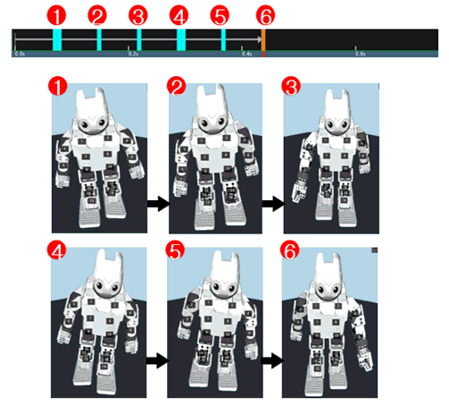
Editing the Key-Frame – Key-Poses are placed on the timeline to create a continuous motion
A Step placed on the timeline is shown by the bar, for an intuitive display of the interpolation pose between each Step.
Editing Flow Control
In the previous version, the link between motion pages, repetition, and playback speed were all dependent on each Page. Due to this it was difficult to reuse data that was created.
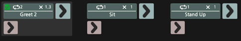
But in Motion 2.0, the flow control (link, repeat, playback speed) is no more dependent on the Motion Unit. So, the Motion Units are now reusable with variations on repetition or speed. Also, by using 2D blocks, arrows, and flow chart, users can easily check on how the final motion will be.
The image below is an example of a motion flow. The final motion will be performed as;
- Play the Motion Unit “Greet 2” twice at 1.3x speed
- Play the Motion Unit “Sit” once at 1.0 speed
- Play the Motion Unit “Stand Up” once at 1.0 speed.
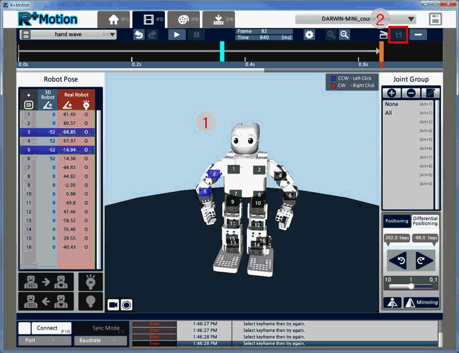
Download Motion File
In the previous version, the motion file size was limited based on the space available on the robot’s controller. So, saving a large file required multiple files to be saved.
In Motion 2.0, the motion project itself has no limitations on the file size. Once a large project is completed, users can just select the Motions they want to download to the robot.
These Motions can be grouped into Motion Groups for easier grouping, and finally, one Motion Group can be downloaded onto the robot.
The bar on the right shows the space taken up (and available) on the robot when selecting the Motions to download.
Each Motion in the Motion Group is named with a Index Number, which can be used in R+ Task to call the specific Motion.
Caution when Downloading If the actual robot was used to playback a motion while editing motions, the saved motion on the robot’s controller is deleted. So, once motion editing is completed, please download the new motion onto the robot’s controller.
Practice
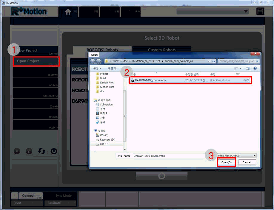
Open Project
- Click “Open Project” on the Home tab.
- Select an example file.
- Click “Open”.
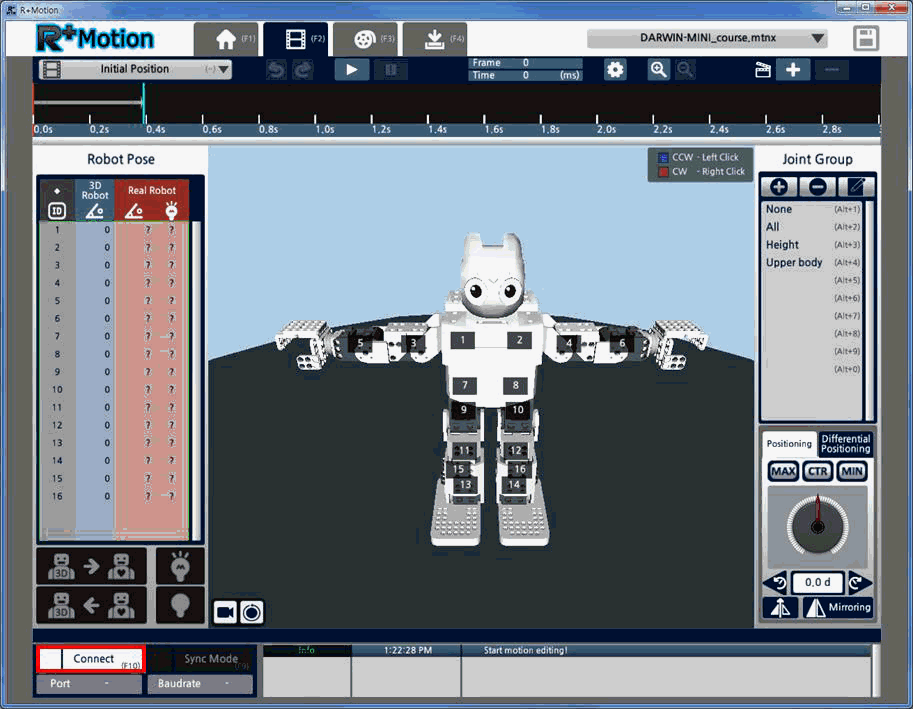
Connect to Robot
-
Click the “Connect” button on the bottom.
-
Select the port the robot is connected to, and click the “Connect” button.
-
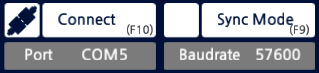
When connection is successful, the port number and baud rate will be shown.
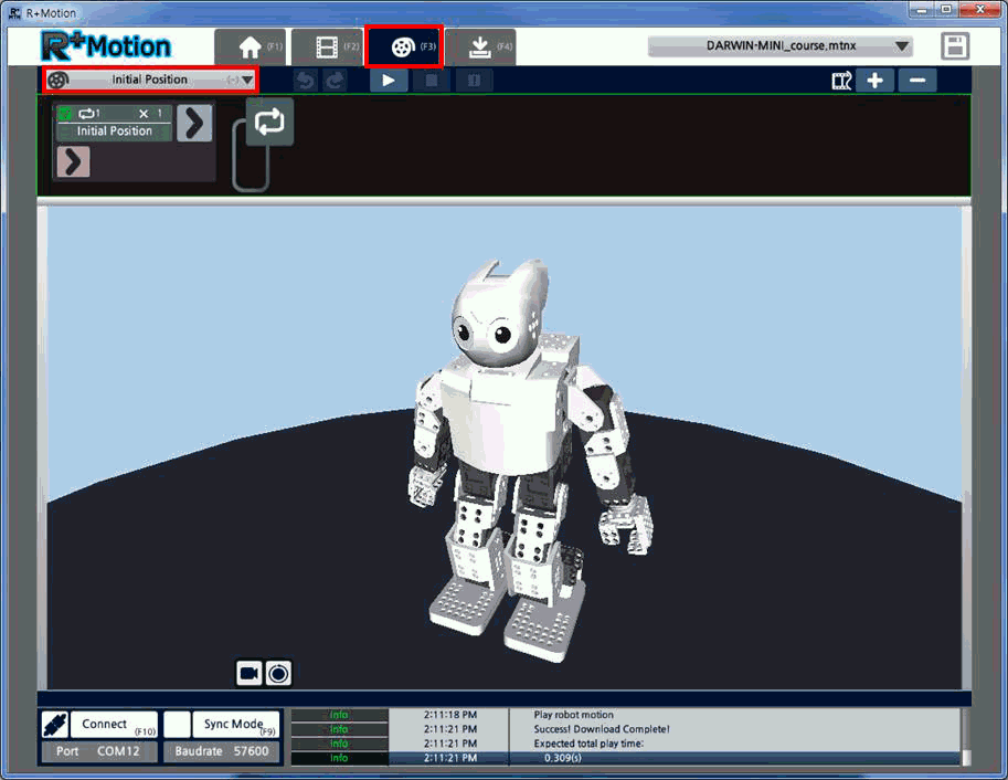
Create New Motion Unit
Motion Unit is the link of poses placed on the timeline, to create a motion. The links between the poses are interpolated, like a fade in/out function.
-
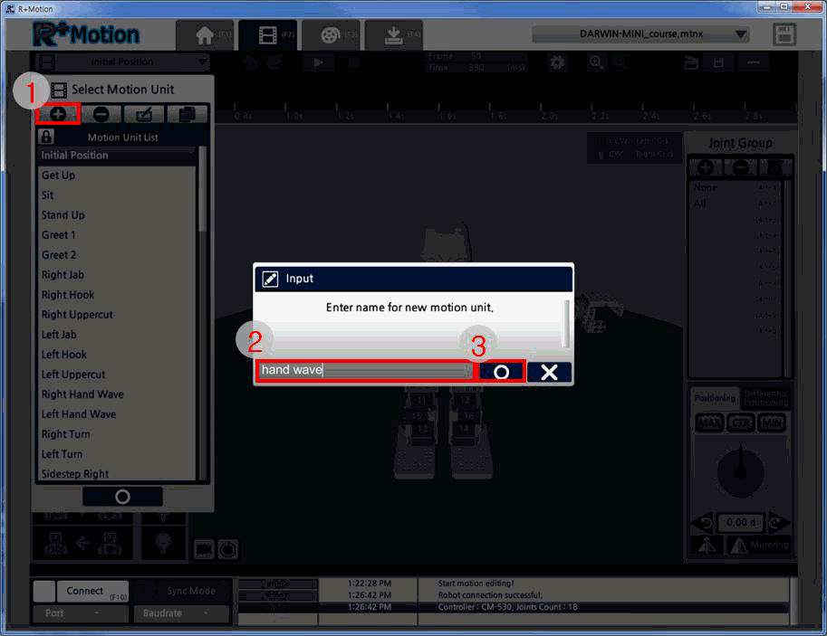
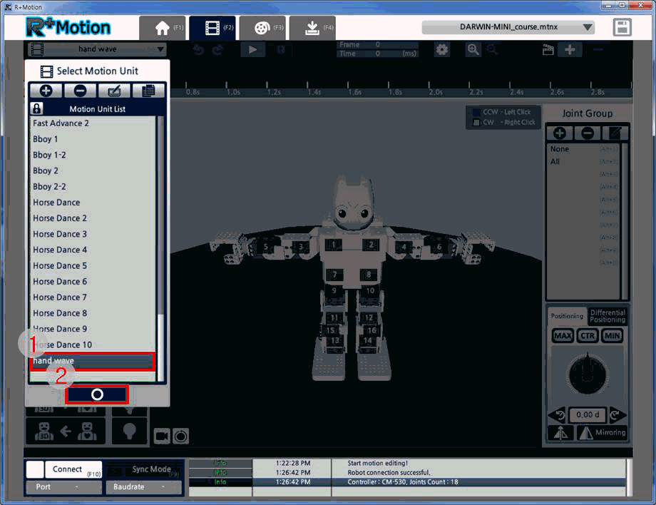
Select the Motion Unit tab, and click on the Motion Unit list on the toolbar.
- Click the “New Motion Unit” button.
-
Name the new Motion Unit and click the “Apply” button.
-
Select the newly created Motion Unit and click the “Apply” button.
Edit Motion Unit(3D Robot)
This section explains how to edit Motion Units when an actual robot is not available. Users will edit the 3D robot’s pose and save the pose on the timeline to create Motion Units.
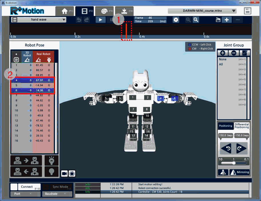
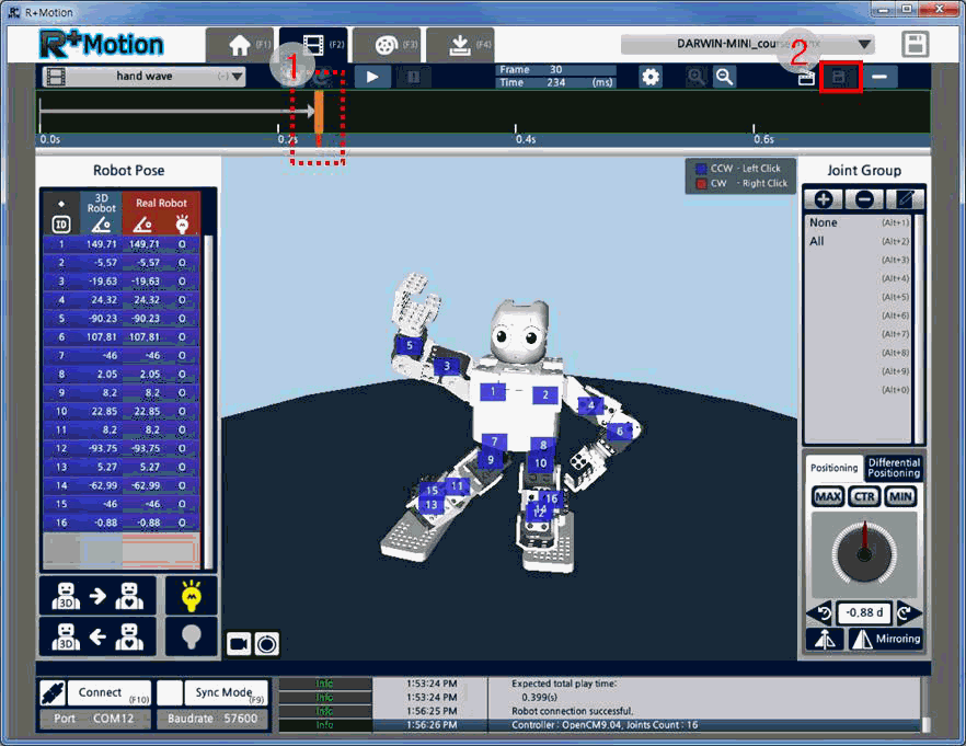
- Click anywhere on the timeline to select a time.
-
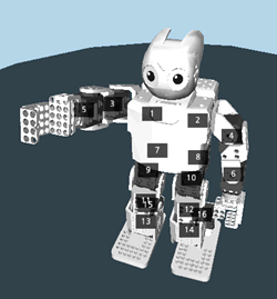
Hold the Ctrl button and select joints 4 and 6.
-
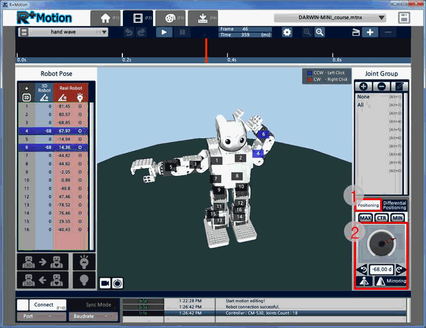
Use the “Positioning” menu on the bottom right to rotate the selected joints. Try creating a pose by moving the robot’s arm joints.
-
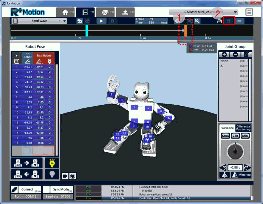
Click the “Insert Key-Frame” button on the top right to insert the created pose on the timeline.

-
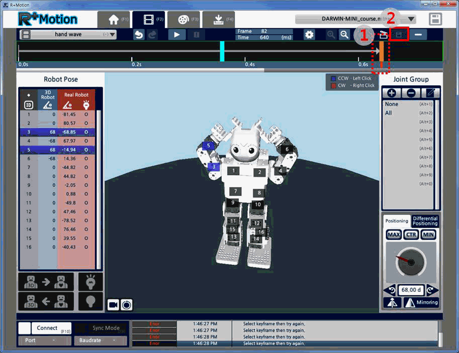
Again, click on another spot on the timeline and click the “Insert Key-Frame” button to insert the same pose again.
-
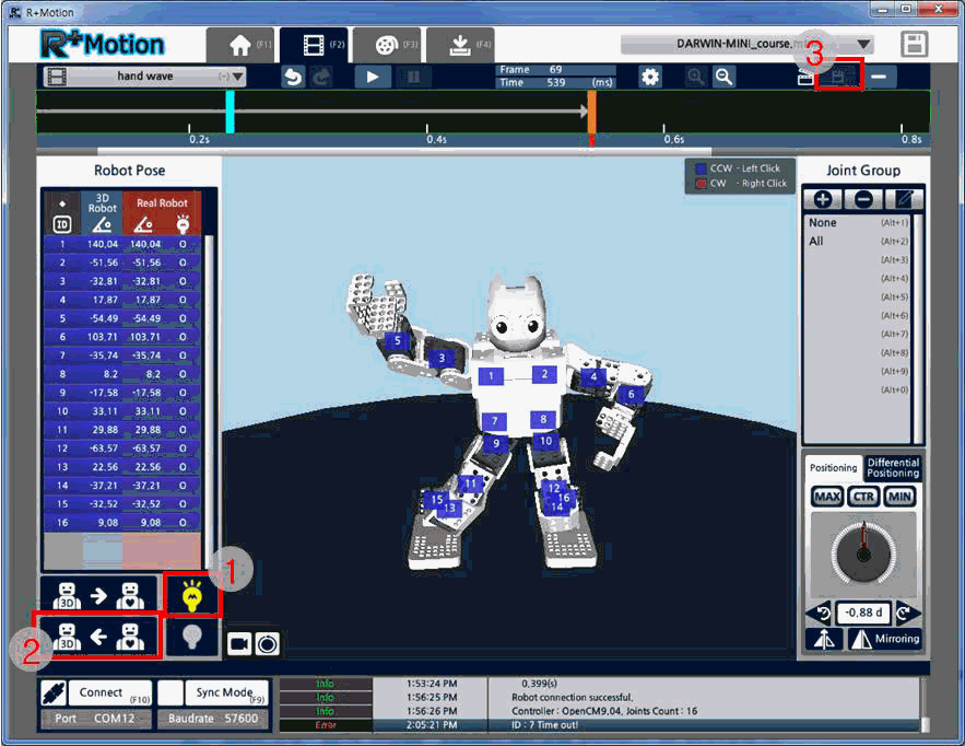
Then, change the 3D robot’s pose the click the “Save Key-Frame” (same button as Insert Key-Frame) to overwrite the previous pose.
-
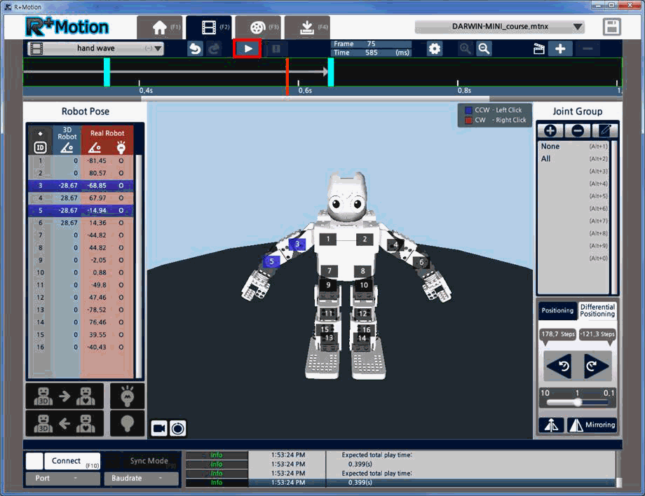
Click the “Play” button on the toolbar to playback the created Motion Unit. The poses created will be played back in the order they were placed on the timeline.
Edit Motion Unit(Actual Robot)
This time, an actual robot will be used to edit a Motion Unit. Users will set the pose using the actual robot, and save the pose onto the timeline.
- Click the “Connect” button on the bottom left to connect to the robot (refer to Connecting the Robot)
- Create a new Motion Unit (refer to Creating a New Motion Unit)
-
Select all the joints, and click on the “Torque Off” button to turn the actual robot’s torque off (for selecting all the motors, you may select any motor then push Ctrl+A).
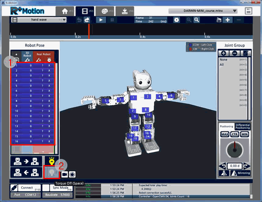
-
Move the actual robot to create the pose to save, click “Torque On”, then click “read Robot Pose” (the 3D robot will mimic the actual robot’s pose).
-
Click anywhere on the timeline and click the “Insert Key-Frame” button to add the pose onto the timeline.
-
Again, click on another spot on the timeline and click the “Insert Key-Frame” button to insert the same pose again.
- Click “Torque Off” to turn the actual robot’s torque off.
-
Move the actual robot to create the pose to save, click “Torque On”, then click “read Robot Pose”.
- Click the “Save Key-Frame” button to overwrite the second pose with the new pose.
-
Click the “Sync Mode” button on the bottom to activate it. (When activated, the 3D robot’s pose is automatically inputted to the actual robot)
-
Click on another spot on the timeline and try setting a third pose. Please always check that the pose doesn’t cause the actual robot to lose balance.
- Click the “Play” button on the toolbar to playback the created Motion Unit. The poses created will be played back in the order they were placed on the timeline.
Create New Motion
Motion is a set of Motion Units linked together. Users can also change the number of repetitions for each Motion Unit or set the playback speed to efficiently create long dance motions. In order to use a motion in a Task code, a Motion (set of Motion Units) must be created.
-
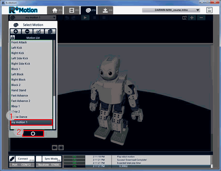
Move to the Motion tab, and click on the list on the toolbar.
- Click the “New Motion” button on the list.
-
Enter a name for the new Motion and click the “Apply” button.
-
Select the newly created Motion and click on the “Apply” button.
Edit Motion
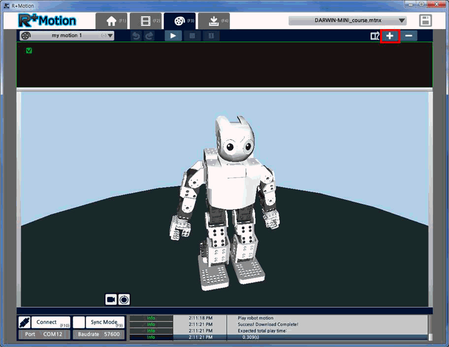
This section will describe how to insert the Motion Units in an empty Motion, and how to edit the playback parameters.
-
Click on the “Insert Motion Unit” button on the top right.
-
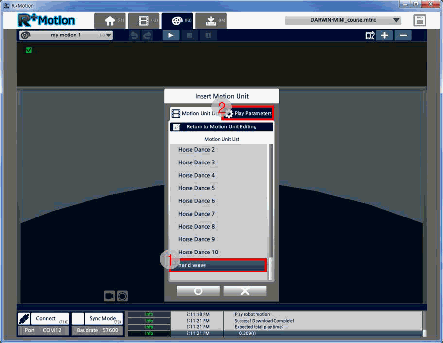
Select the Motion Unit to insert and click on the “Play Parameters” tab.
-
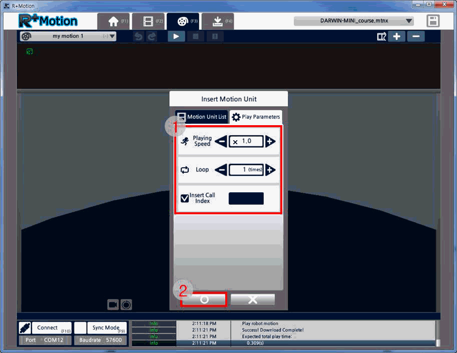
In the Play Parameters tab, users can edit the Motion Unit’s playback speed, repetition number, and Index Number. For now, don’t change any setting and just click “Apply”.
-
Check the Motion Unit that is inserted and click the “Play” button to check the Motion.
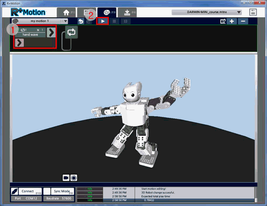
- Double-click on the inserted Motion Unit to change it into a different Motion Unit, or change the Play Parameters.
- Double-click on the
Green Arrowto insert another Motion Unit to be played back after the current Motion Unit. -
Double-click on the
Pink Arrowto insert a Exit Motion Unit that is played when a current Motion Unit is interrupted by a particular command, parameter or etc.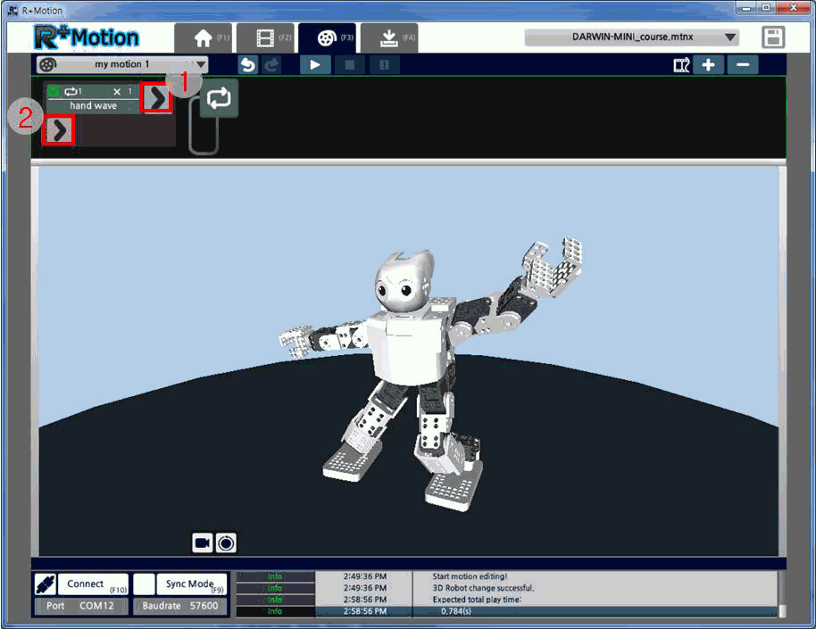
-
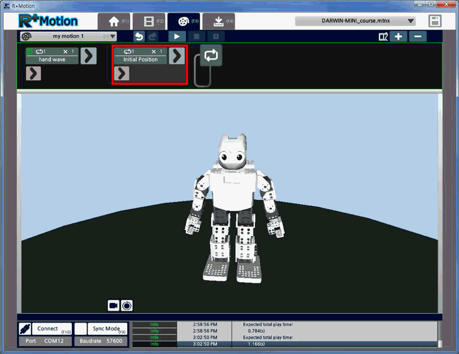
Double-Click on the “Green Arrow” and insert the “Initial Position” Motion Unit.
-
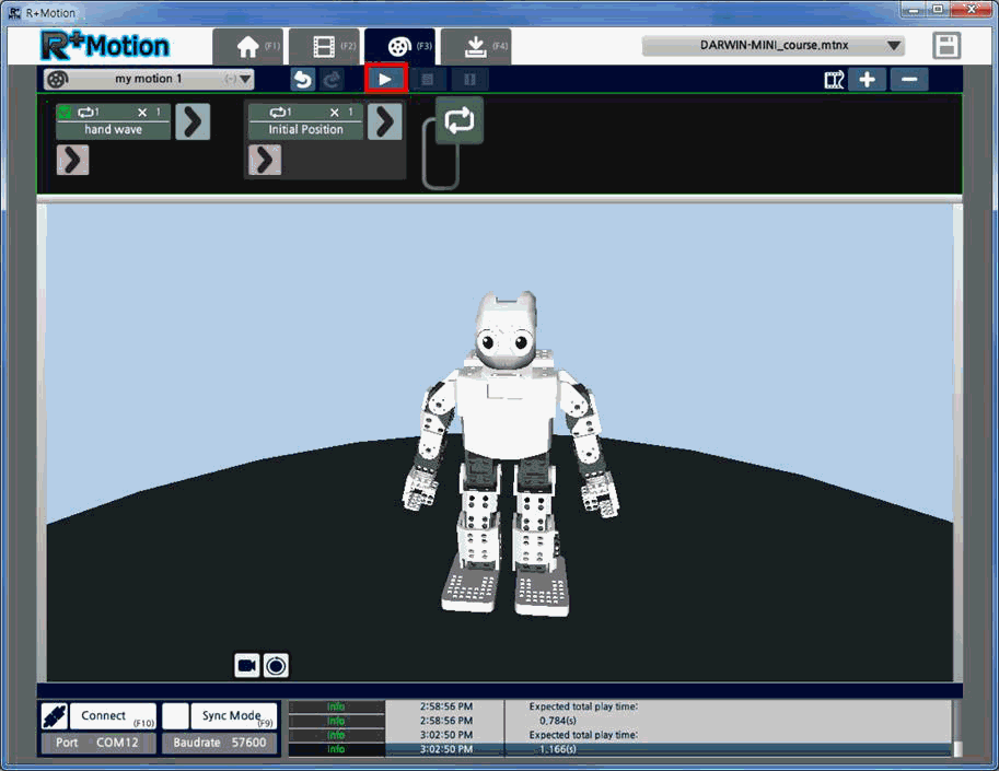
Let’s playback the completed Motion.
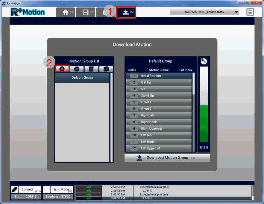
Create New Motion Group
The Motion Group must be created to download motions onto the robot. The Motion Group is a group of selected Motions to be downloaded on the robot.
-
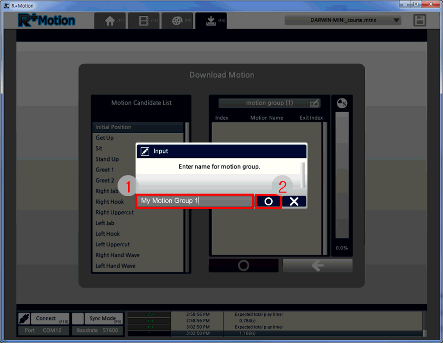
Move to the Motion Download tab and click on the “New Motion Group” button.
-
Enter the name for the new Motion Group and click “Apply”.
-
Out of the Motion Candidate List, select the Motions to be inserted into the new Motion Group, and click on the “Add Motion” button.
The bar on the right will update in real-time to display the storage space status. Click “Apply” to create the Motion Group.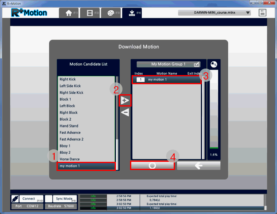
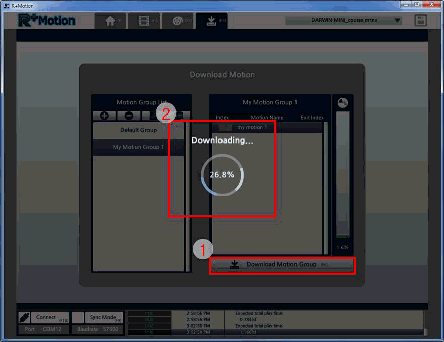
Download Motion
-
Out of the list of Motion Groups, select the Motion Group to download onto the robot. Please make sure to check that the Motion Group size doesn’t exceed the space available on the robot.
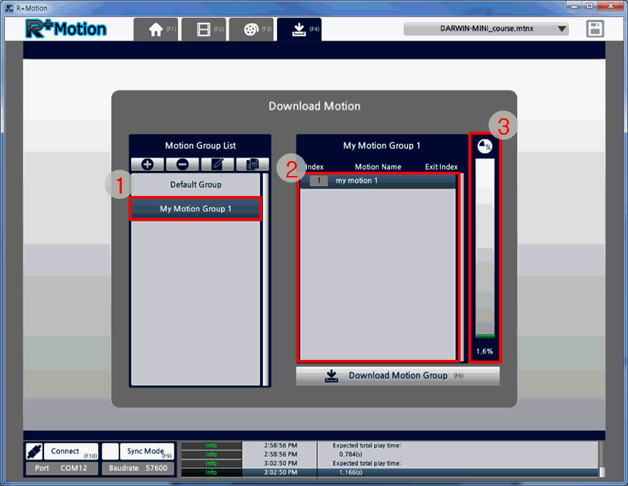
-
Click on the “Motion Group Download” button the download onto the robot. The download progress will be shown on the center of the screen.
Useful Tips
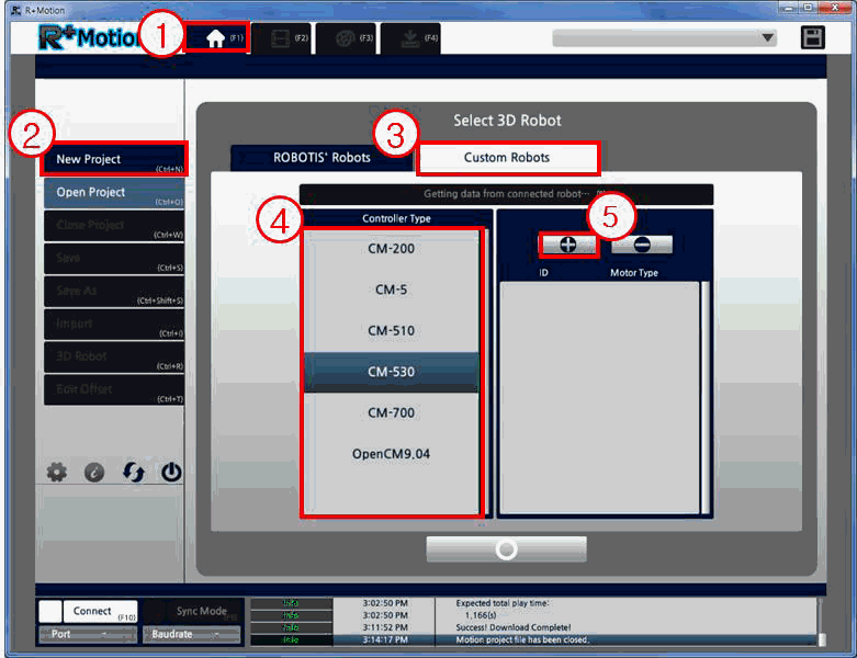
Create Custom Robot
- Move to the Home tab and click on the “New Project” button.
-
Move to the “Custom Robots” tab, select the controller to use, and click on the “Add Joint” button.
-
Select the type of joint (motor) to use and set its ID. Click “Apply” to add the joint to the joint list.
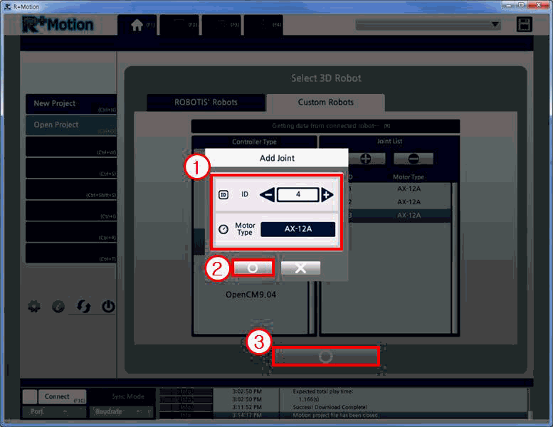
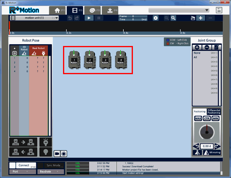
- Once the joint list is completed and the new project is created, the custom robot will be shown on the screen.
Since it is difficult to analogize and display the actual custom robot on the 3D model, it will be helpful if the users frequently playback the motion on the actual robot (Sync Mode) to check on their status.
Change 3D Robot
The Motion file is created and edited based on the initial 3D robot that was selected. Users can change the 3D robot while in the midst of a project, while maintaining the motion file data.
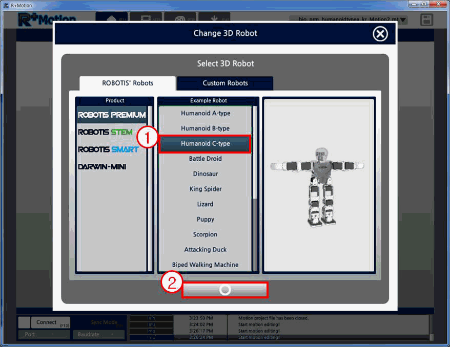
The guide below is an example of changing the 3D robot from “Humanoid A-type” to “Humanoid C-type”.
-
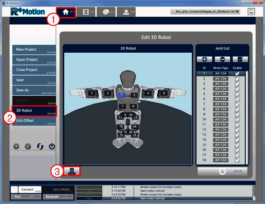
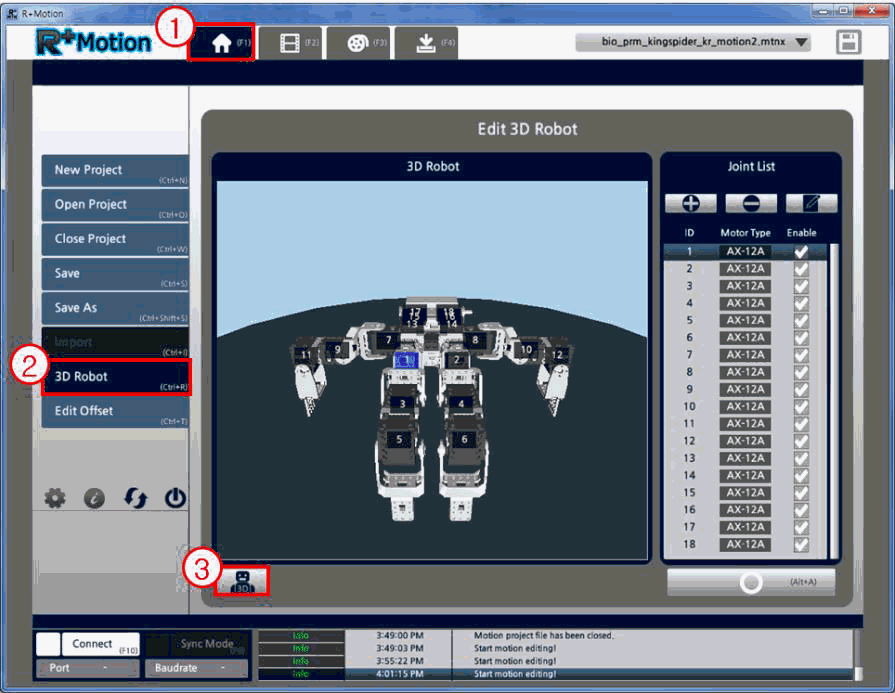
Move to the Home tab, and click on the “3D Robot” button on the left.
-
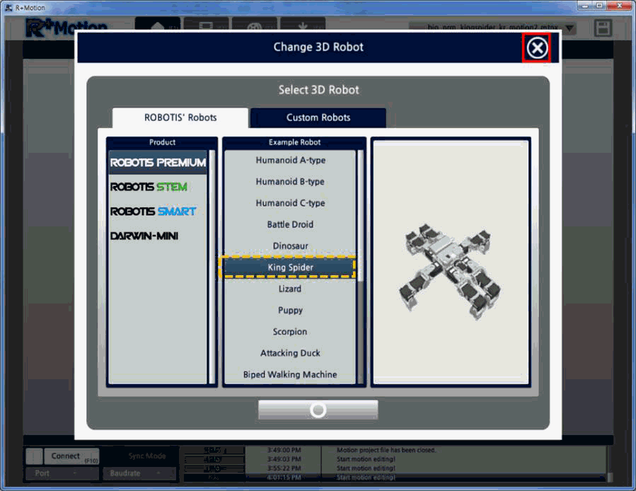
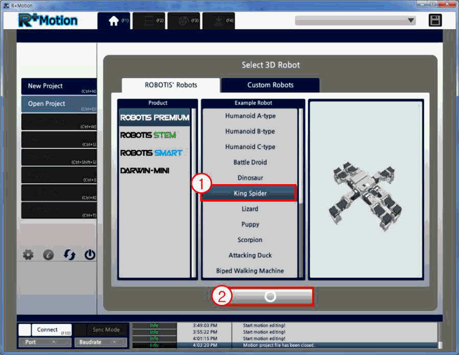
Click on the “Change 3D Robot” button on the bottom, and select the robot to be change into.
- Once the 3D robot is changed, the window will automatically change.
-
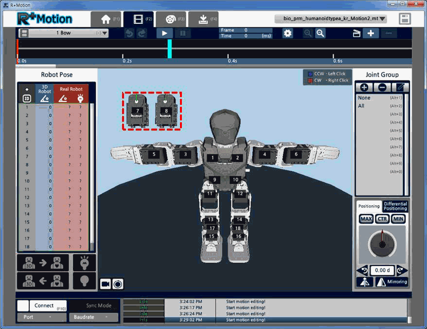
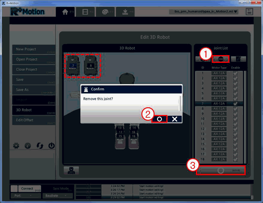
If there are unnecessary joints, such as the two motors depicted below, it is recommended to delete them. Move to the Home tab again and click on the “3D Robot” button. (If there are no joints to delete, please skip step 5)
-
Select the motors to delete, and click on the “Remove Joint” button to delete. Once you are done with deleting, click the “Apply” button.
-
The unnecessary joints are now deleted.
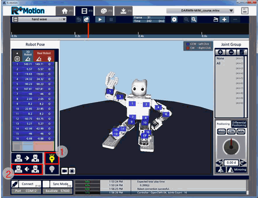
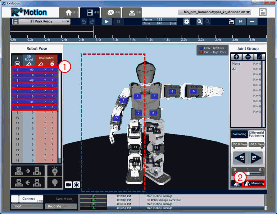
Pose Mirroring
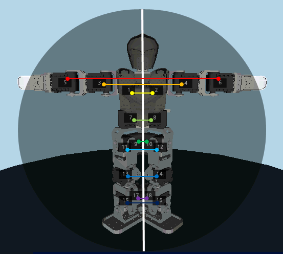
The 3D Robot’s joints have a horizontally symmetrical matching joint on the opposite side, based on the vertical center line drawn below.
The Mirroring function uses this symmetry for mirroring or exchanging the pose on the opposite side.
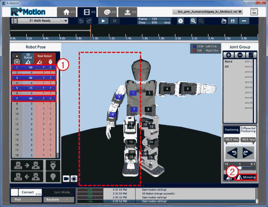
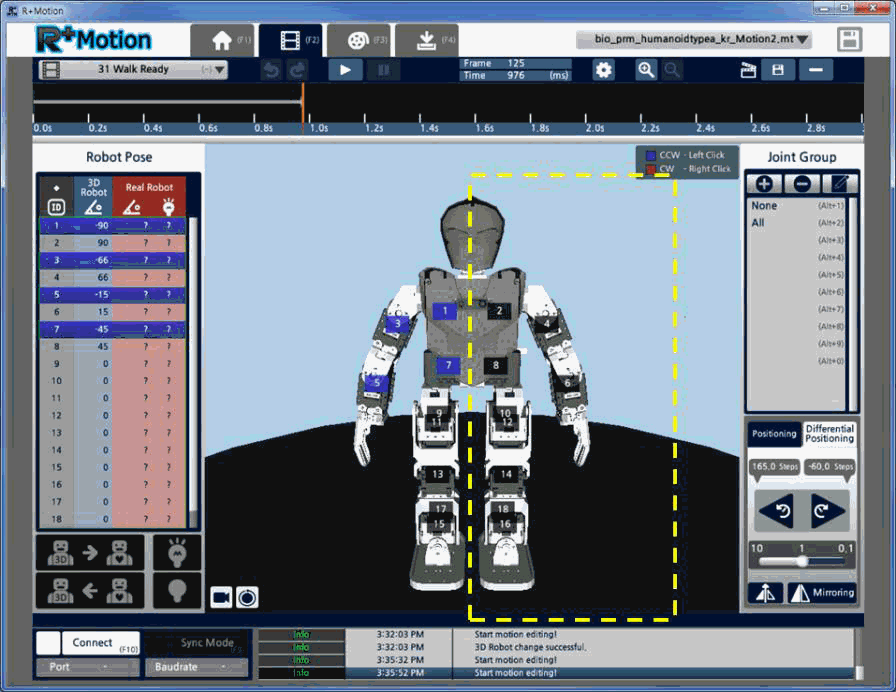
Pose Symmetry
- For Pose Symmetry, users must first select the joints that will be the basis for the opposite side.
-
Click on the “Mirroring” button.
-
The selected joints’ values will now be entered (mirrored) onto the horizontally symmetrical joint on the opposite side.
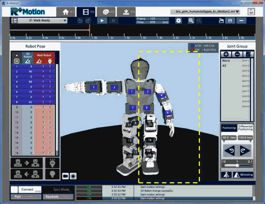
Pose Exchange
-
For Pose Exchange, users must select the joints that will be the basis for exchanging, and also select the corresponding joints that will receive the values from the basis joints.
-
Click on the “Mirroring” button.
-
The selected joints will now have their values exchanged with each other.
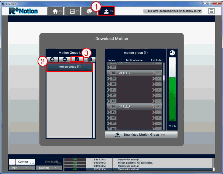
Edit Motion Index Number
The Motion Index Number is used when a motion data has to be called in RoboPlus Task.
The Index Number of the Motion data downloaded on the controller must match the Index Number used for calling in Task.
-
Move to the “Motion Download” tab, select a Motion Group for editing its Index Number, and click on the “Edit Motion Group” button.
-
Select the Motion Number you would like to edit the Index (or Exit Index) number for, change the number, and click the “Enter” key.
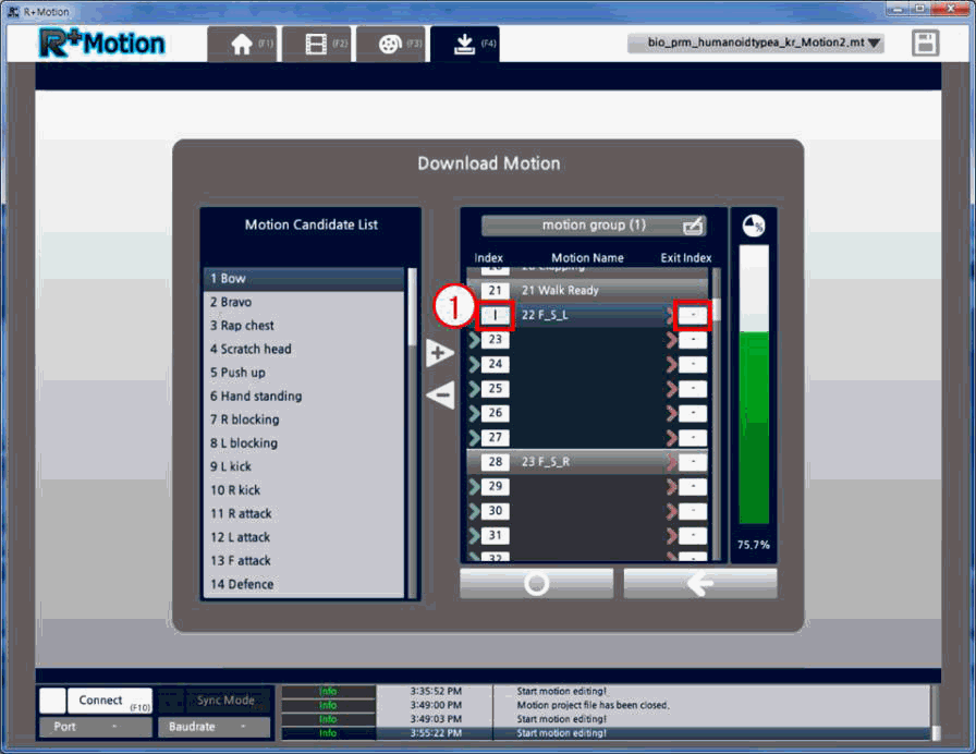
-
If a duplicate number is already present, a message will be shown as below, and the user must select how to proceed.
If the Exit Index is not inputted, a random number will be assigned.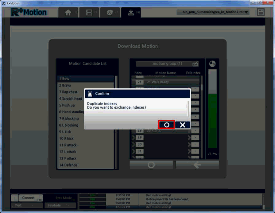
Copy Motion Data
- Open the Motion file with the data to copy.
-
Move to the “Home” tab, click the “3D Robot” button, and click on the “Change 3D Robot” button.
-
Check the 3D Robot of the Motion file, and close the “Change 3D Robot” window.
-
Run another Motion 2.0 program file, and create a new project with the 3D robot you checked in step 3.
-
Open the list of Motion Units, and select the Motion to copy with Ctrl+C.
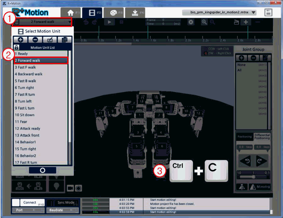
-
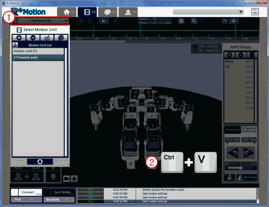
In the other Motion 2.0 window, with the new project, open the Motion Unit list and push Ctrl+V to paste the copied Motion Unit.
CAUTION : When copying data between Motion files
- Data that can be copied : joint value, Key-Frame, Motion Unit, and Motion.
- If a data with the same name already exists in the new (blank) project, the data will not copy.
- Copying must be proceeded in the order of Motion Unit -> Motion. If a Motion is copied without copying any Motion Units, an empty Motion will be pasted.
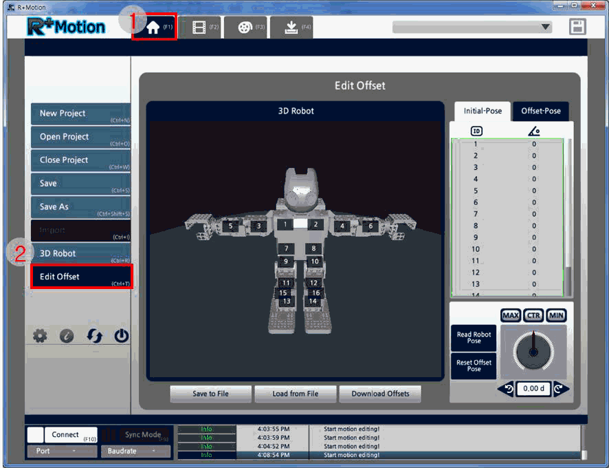
Edit Offset
-
Move to the “Home” tab and click on the “Offset” button.
- Connect the robot (refer to Connecting the Robot)
- Turn on the Sync Mode.
-
Set the initial pose, check the robot, and edit the offset pose.
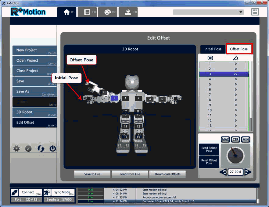
- The ideal offset is when the actual robot’s pose is identical to the initial pose.
- Adjust the offset so the actual robot’s pose matches the 3D robot’s initial pose.
-
Click on the “Download Offsets” button to save the offset onto the robot’s controller.
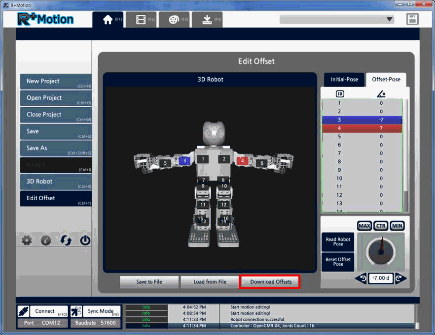
- The difference between the initial pose and the offset pose will be applied as the offset.
(Offset pose – Initial pose = Offset)
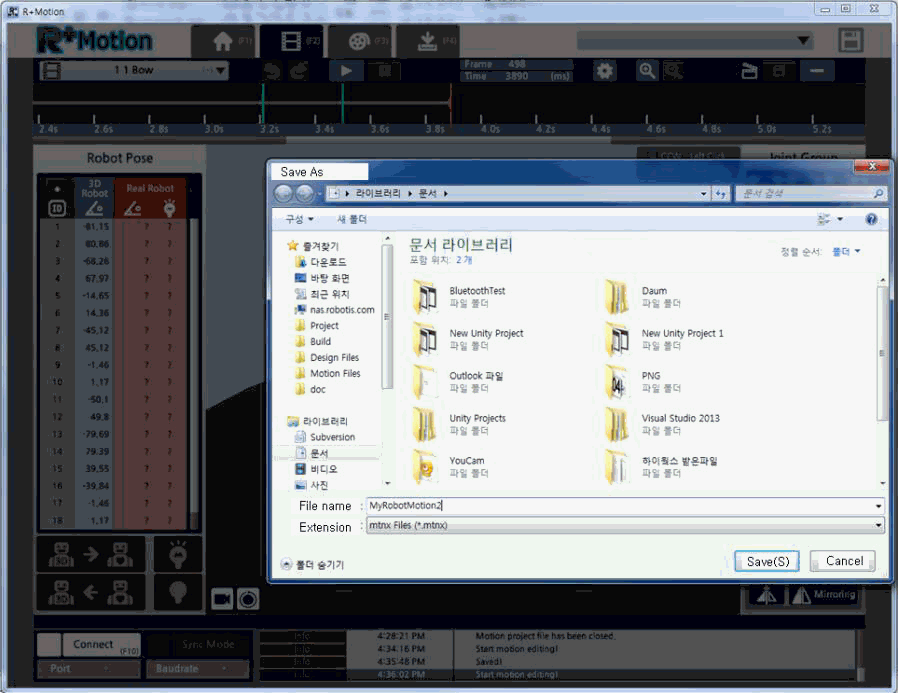
Convert mtn File
RoboPlus Motion 2.0 (R+ Motion 2.0) can also open the old RoboPlus Motion 1.0 file (*.mtn) as well. But, users will have to convert the file in *.mtnx first.

CAUTION : After the mtn file is converted in an mtnx file, the storage capacity or Motion Index Number may be altered. Once you have converted the file, please check the Index Numbers again.
-
Run RoboPlus Motion (1.0)
-
Connect the robot, and open the Save As window to save the mtn file.
-
Enter the file name and click “Save”.
-
Run R+ Motion 2.0. Click “Open Project”, and change the file type extension on the list to “mtn Files”.
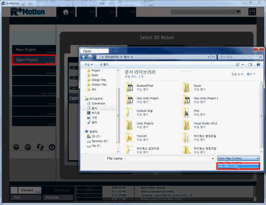
-
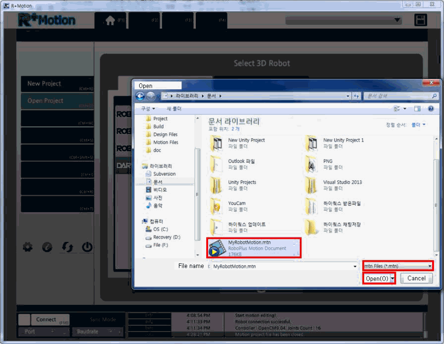
Select the mtn file to change into an mtnx file, and click “Open”.
-
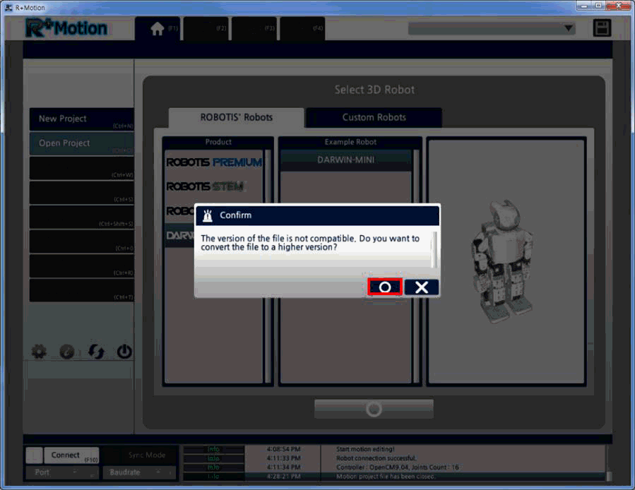
A window will pop-up asking the user if you want to convert the file. Click “Apply”.
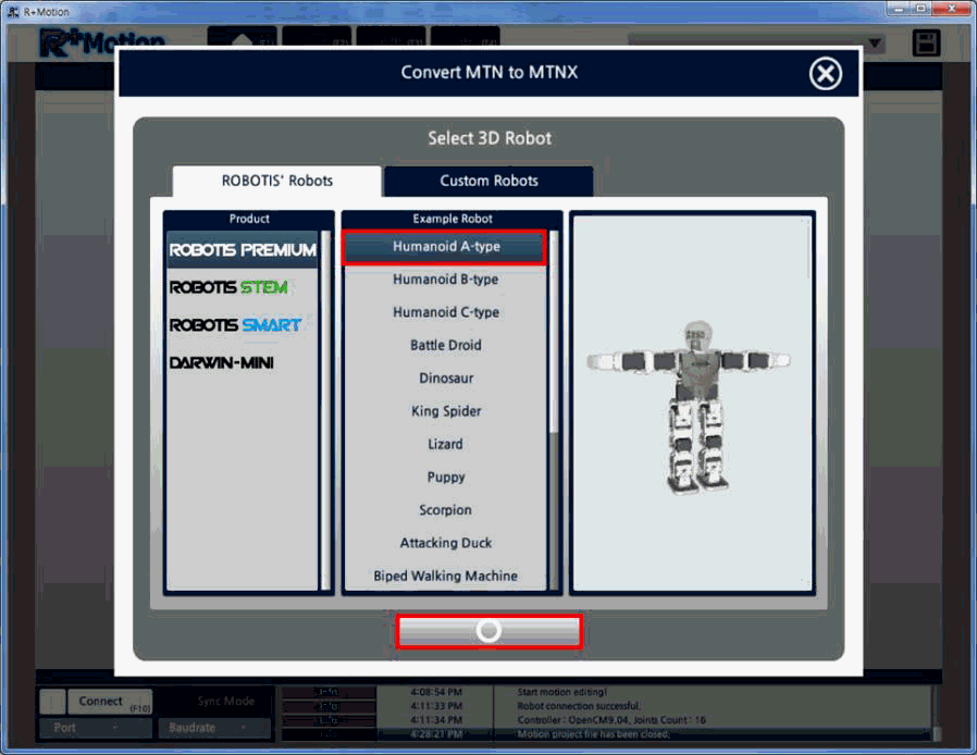
-
Select the 3D robot that will be using the Motion data and click “Apply”.
-
Once converting is completed, click on the “Motion Unit List” on the top left to check if converting was correctly processed.
-
Save the converted mtnx file.
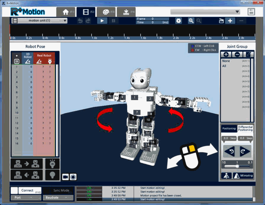
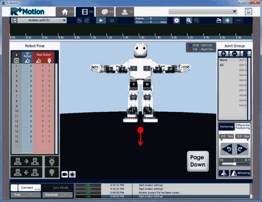
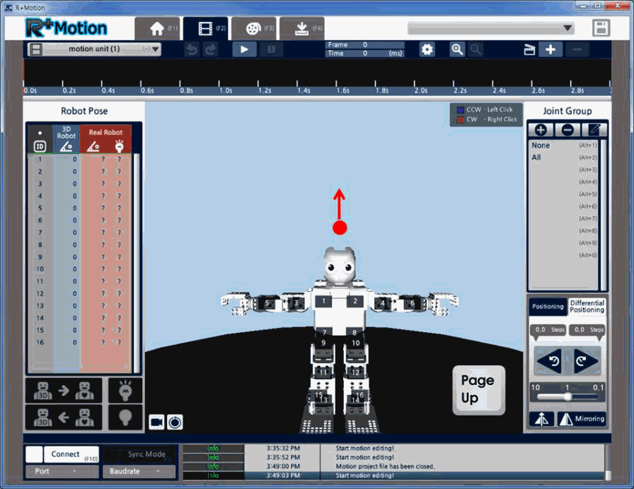
Control 3D Camera
-
Hold the right mouse button and drag to rotate the point of view.
-
Push the Home key or scroll up on the mouse to zoom in.
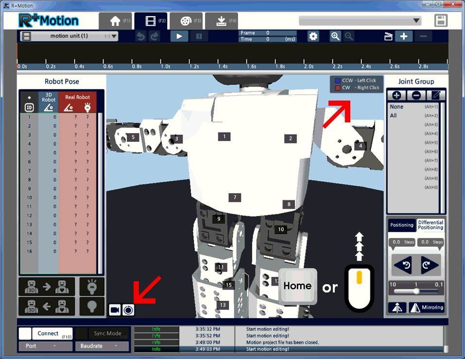
-
Push the Endkey or scroll down on the mouse to zoom out.
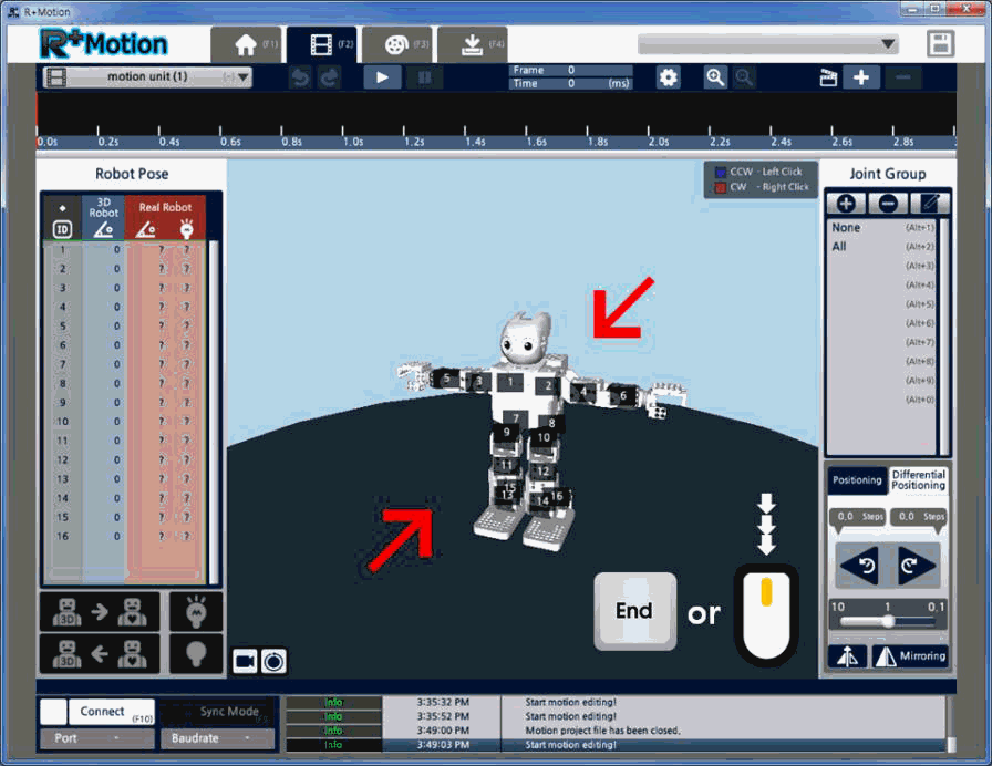
-
Push the Page Down key to move the POV vertically down. (the robot will now be displayed as if you’re looking up at it)
-
Push the Page Up key to move the point of view vertically up. (the robot will now be displayed as if you’re looking down at it)
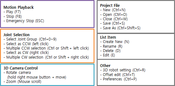
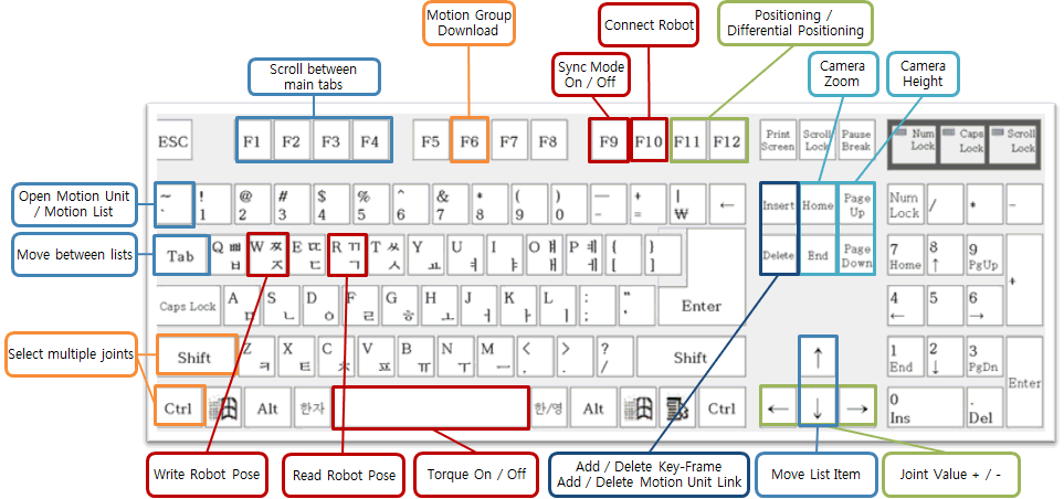
Shortcut Keys
FAQ
- Which products are supported?
PREMIUM, STEM, SMART, DARWIN-MINI CM-200, CM-510, CM-530, CM-700, OpenCM9.04C, AX series, MX series, robots made with XL-320 All products supporting TTL / RS485 communication
- Which 3D models are supported?
All example robots of the products supported (listed above)
- How many joints are supported?
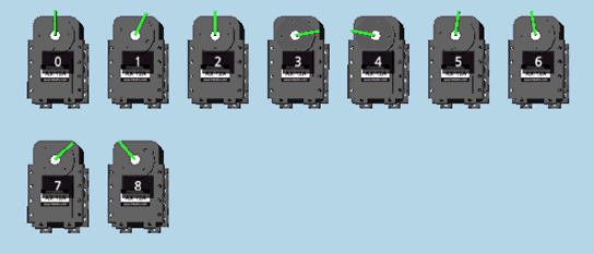
If using DYNAMIXEL’s, 26 joints can be used, from ID 0~25. If using CM-200, 8 joints can be used, from ID 3~10.
- Can other 3D models be added?
Currently, customs robots can only be displayed by an array of motors shown on the screen. In the future, users will be able to import robots created from R+ Design (PC version only).
- Can the MTN file be converted into MTNX file?
Please refer to the e-Manual page “Converting the old file (*.mtn)”
- Can the MTNX be converted into MTN?
Not supported, and currently there is no plan to support it in the future.
- The motion is not performing correctly after the editing the Motion file. How can I solve this?
You must download the Motion Group to the robot after editing the Motion file.
- The controller is not connecting properly. How I can I solve this?
Please try turning the controller ON/OFF. (If you’re using CM-200, turn the controller off, hold the power button for 2~3 sec to stop the task, and try again.
- What is the “Multiplier” in a Joint Group?
Multiplier is used when adjusting multiple joints simultaneously, but the users want to adjust each joint value with different weight. Increasing/decreasing the Multiplier value will change the weight of the adjustment.
Calculation : current angle = previous angle + (rotating direction x multiplier x number of clicks)