Introduction
DYNAMIXEL Shield was created to use RC-100 and DYNAMIXEL on arduino board. We provide dynamixel library for DYNAMIXEL Shield, it can help you to use DYNAMIXEL easily.
This product does not contain Arduino Board. Arduino Board should be purchased separately.
Specifications
| Item | Details |
|---|---|
| Operating Voltage | 5 V (XL-330) ~ 24 V (PRO / X Series) |
| Maximum Current | 1 A(Arduino), 10 A (Terminal Connector) |
![]()
DANGER
(Ignoring these warnings may cause serious injury or death)
- Never place items containing water, flammables/open flames, or solvents near the product.
- Never place fingers, arms, toes, and other body parts near product during operation.
- Cease operation and remove power from the product if the product begins to emit strange odors, noises, or smoke.
- Keep product out of reach of children.
- Check input polarity before installing or energizing wiring or cables.
![]()
CAUTION
(Ignoring these warnings may cause mild injury or damage to the product)
- Always comply with the product’s offical operating environment specifications including input voltage, current, and operating temperature.
- Do not insert blades or other sharp objects during product operation.
![]()
ATTENTION
(Ignoring these warnings may cause minor injury or damage to the product)
- Do not disassemble or modify the product.
- Do not drop the product or apply strong impacts.
- Do not connect or disconnect DYNAMIXEL cables while power is being supplied.
Supported DYNAMIXEL
1 RX, DX, EX series are by default disabled and require config.h modification in DYNAMIXEL2Arduino to be used.
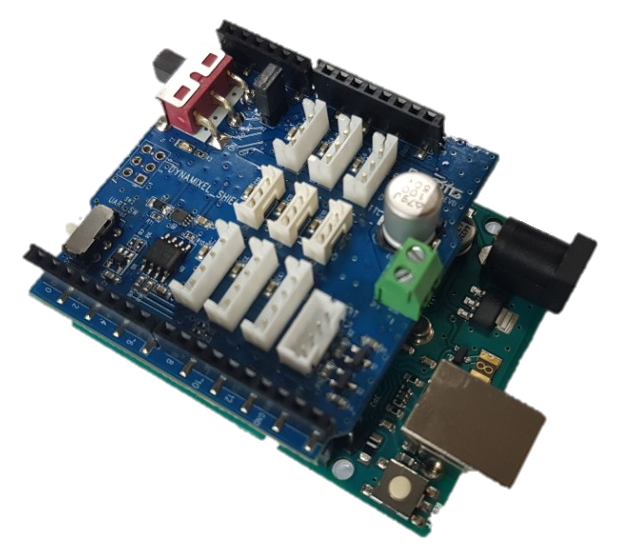
Layout
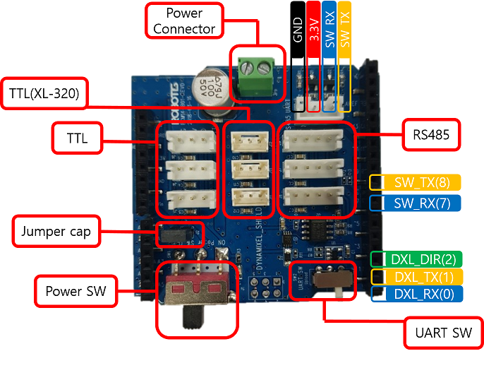
The DYNAMIXEL Shield has the same pin position as Aruduino UNO. To find the pinout diagram, see Arduino Offical page.
| Pin No. | Pin Name | Description |
|---|---|---|
| 0 | HW UART RX | DXL_RX |
| 1 | HW UART TX | DXL_TX |
| 2 | HW UART DIR | DXL_DIR(DXL_TX_EN) |
| 7 | SW UART RX | Caution2 SoftwareSerial |
| 8 | SW UART TX | Caution2 SoftwareSerial |
| Item | Description | Note |
|---|---|---|
| DYNAMIXEL Port | TTL, TTL(XL-320), RS485 | Caution3 |
| Power Switch | Power SW (DYNAMIXEL Port Power Switch) | - |
| UART Switch | UART SW (Upload or DYNAMIXEL Select Switch) | Caution1 |
| Jumper Cap | Power Source Selection | Read ‘Connecting Power’ |
- DXL_RX (0), DXL_TX (1) : Hardware serial port to communicate with DYNAMIXEL.
- DXL_DIR(2) : Flow control of DYNAMIXEL packet.
- The hardware serial port is used to communicate with DYNAMIXEL, therefore, RC-100 or LN-101 has to be connected to the software serial communication port(SW TX/RX) via Arduino pin 7 and 8.
Caution1 When uploading firmware using USB port, you should switch the UART SW(SW_2) to Upload mode. When you select the UART SW (SW_2) to DYNAMIXEL mode, you can use DYNAMIXEL but USB port.
Caution2 If you are using a board that does not support SoftwareSerial(like SAMD, etc..), you cannot use pins 7 and 8 for UART purposes.
Caution3 TTL, TTL (XL-320) and RS485 connectors are all connected in parallel in one serial.
Use of Serial Monitor with DYNAMIXEL Shield
DYNAMIXELShield uses serial pins (0,1) which are the same pins as Arduino Uno / Mega. When using the serial monitor, it may cause unexpected issue with data in the board due to a port conflict.
In order to prevent the board from the port conflict, be sure to read How to Use Serial Monitor with DYNAMIXEL Shield carefully.
How to Use Serial Monitor with DYNAMIXEL Shield
Check the type of your arduino board, and select the either of listed solution to use Serial Monitor with DYNAMIXEL Shield.
- [Recommanded] #define DEBUG_SERIAL
- See #define DEBUG_SERIAL in the DynamixelShield Examples in Arduino.
- Use UART port of DYNAMIXEL Shield ( AVR 8 bit board including Uno / Mega boards)
- AVR 8 bit boards, such as Uno, and Mega, can use the serial monitor by using DYNAMIXEL Shield’s pins, which is read UART (See Layout)
NOTE: Be sure to use
SoftwareSerialLibrary to use the serial port with DYNAMIXEL Shield and AVR 8 bit boards as the port is designed for the use of general pins. Prefered Comunication Modules: BT-210, BT-410, LN-101. - Use USB Port
- When you use other arduino boards except Uno and Mega, use the serial monitor via USB port.
- Use USB to Serial converter
- You can use either SoftwareSerial or HardwareSerial ways. See Arduino Reference page of Serial, and determine your board whether or not it support either of ways (SoftwareSerial or HardwareSerial).
- Use UART Port
- DYNAMIXEL Shield contains UART pins: 7(RX), 8(TX). They are only compatible with AVR 8 bit board, such as Uno and Mega boards. In order to use this port, use other HardwareSerial pins instead of 7(RX), 8(TX). To determine wheather boards has HardwareSerial, and its pin numbers see Arduino Reference page of Comunication.
Connecting Power
| Connect VIN | Disconnect VIN |
|---|---|
 |
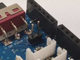 |
- The power input is divided as follows depending on whether the jumper cap is connected or not.
- Connect VIN : Power supply using with Arduino’s SMPS connector
- Disconnect VIN : Power supply using DYNAMIXEL shield’s power input connector. Can not use power from arduino.
- Since DYNAMIXEL power can not be connected to the USB power of the Arduino board, you need to connect the external power.
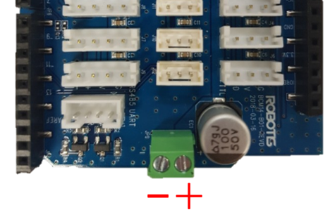
- When using the power input connector, be sure to check the polarity of the power supply.
Switches
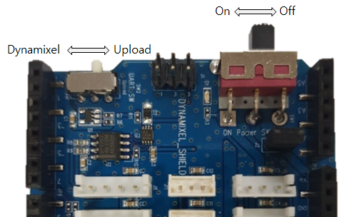
Upload Switch
- For DYNAMIXEL control, the hardware serial port of the arduino board is used. Because the downloading is done to the same port, the two ports may collide. Therefore, to download, use serial port switch to move to upload position and download.
- After the download is completed, the switch must be moved to DYNAMIXEL position for DYNAMIXEL control. If it is not moved, DYNAMIXEL will not work.
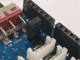
DYNAMIXEL Power Switch
- It is a switch that can turn on / off the power of DYNAMIXEL connector.
DYNAMIXEL Shield Libraries
DYNAMIXEL2Arduino Library : GitHub Repository
DYNAMIXEL Shield Library : GitHub Repository
Features
- Compatible to Arduino boards
- Support dynamixel protocol 1.0/2.0
- Up to 16 DYNAMIXEL’s can be controlled (Typically, each motor(XL-320 or XL430-W250) consumes 0.4 ~ 0.6A of current)
- Support SynWrite function
- Support RC-100 library
- Serial communication using software serial library
- DYNAMIXEL Shield library(v0.1.0 or above) requires DYNAMIXEL2Arduino library
Install Library
There are three ways to add libraries to the Arduino IDE.
- Using the Library Manager
- Importing a .zip Library
- Manual installation
Each way is described in detail in the Arduino Official Guide, so please refer to it if necessary.
Below is an example of using the Library Manager.
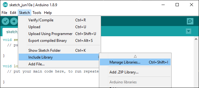
Search for dynamixel shield from the Library Manager and install the latest version.
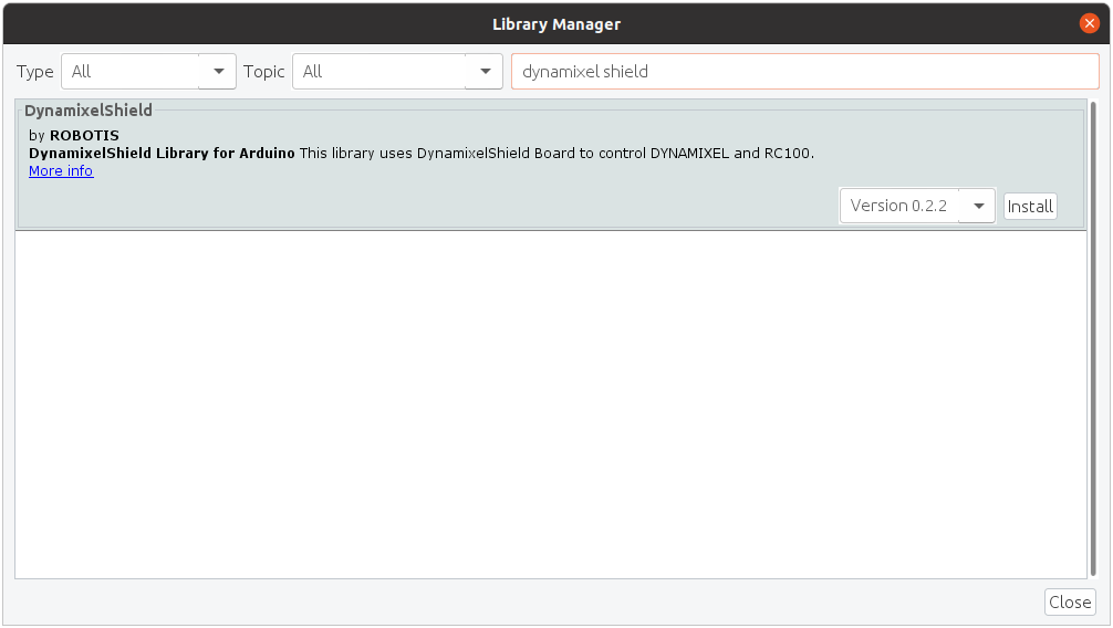
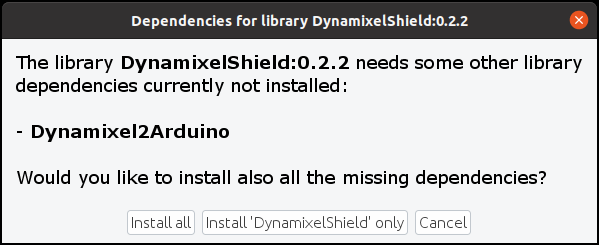
Click Install all to install the dependent library Dynamixel2Arduino.
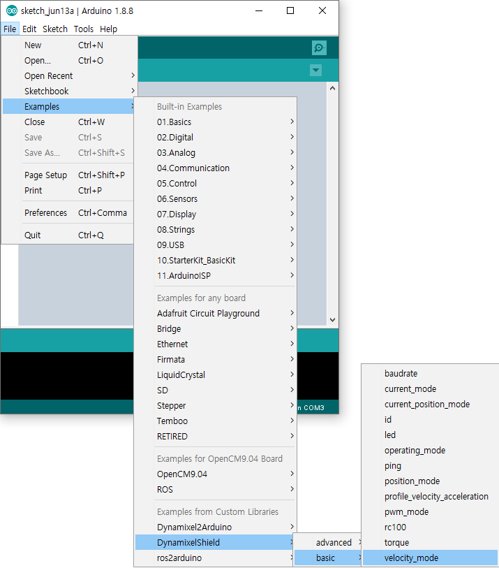
If you have successfully installed both libraries, you’ll be able to find several examples of DynamixelShield in the examples.
Library API
DYNAMIXELShield(v0.1.0 or above)
WARNING : In order to use DYNAMIXEL Shield library(v0.1.0 or above), DYNAMIXEL2Arduino library must be installed.
Dynamixel2Arduino Class
- begin()
- getPortBaud()
- ping()
- scan()
- getModelNumber()
- setID()
- setProtocol()
- setBaudrate()
- torqueOn()
- torqueOff()
- ledOn()
- ledOff()
- setOperatingMode()
- setGoalPosition()
- getPresentPosition()
- setGoalVelocity()
- getPresentVelocity()
- setGoalPWM()
- getPresentPWM()
- setGoalCurrent()
- getPresentCurrent()
- readControlTableItem()
- writeControlTableItem()
Master Class
Dynamixel2Arduino class inherits below public functions from the Master class.
RobotisRemoteController Class
- begin()
- availableData()
- readData()
- availableEvent()
- readEvent()
- flushRx()
- available()
- read()
- peek()
- flush()
- write()
DynamixelShield(v0.0.5)
WARNING : This version of DYNAMIXEL Shield API is deprecated and not maintained anymore.
bool begin(uint32_t baud_rate = 57600, uint8_t protocol_version = DXL_PACKET_VER_2_0);

bool scan(void);
bool ping(uint8_t id = DXL_GLOBAL_ID);
bool addMotor(uint8_t id, uint8_t model);
bool setProtocolVersion(uint8_t version);
bool write(uint8_t id, uint16_t addr, uint8_t *p_data, uint16_t length, uint32_t timeout);
bool read(uint8_t id, uint16_t addr, uint8_t *p_data, uint16_t length, uint32_t timeout);

uint8_t getDxlCount(void);
uint8_t getDxlID(uint8_t index);
uint32_t getErr(void);
void clearErr(void);

bool reboot(uint8_t id);
bool reset(uint8_t id);

bool setID(uint8_t id, uint8_t new_id);
bool setBaud(uint8_t id, uint32_t new_baud);

bool ledOn(uint8_t id);
bool ledOff(uint8_t id);

bool torqueOn(uint8_t id);
bool torqueOff(uint8_t id);

bool setJointMode(uint8_t id);
bool setWheelMode(uint8_t id);

bool    setGoalPosition(uint8_t id, uint32_t position);
int32_t getGoalPosition(uint8_t id);
int32_t getCurPosition(uint8_t id);

bool    setGoalSpeed(uint8_t id, int32_t speed);
int32_t getGoalSpeed(uint8_t id);
int32_t getCurSpeed(uint8_t id);

bool    setGoalAngle(uint8_t id, int32_t angle);
int32_t getGoalAngle(uint8_t id);
int32_t getCurAngle(uint8_t id);

bool syncWriteBegin(void);
bool syncWriteEnd(void);
Reference
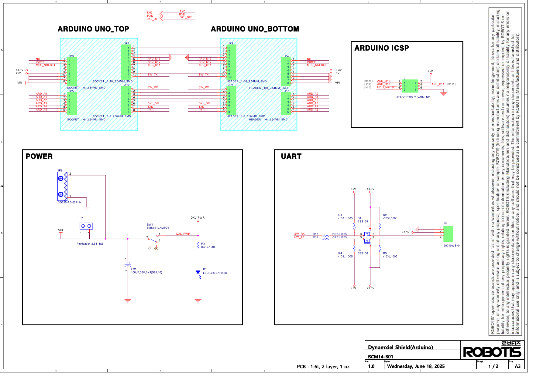
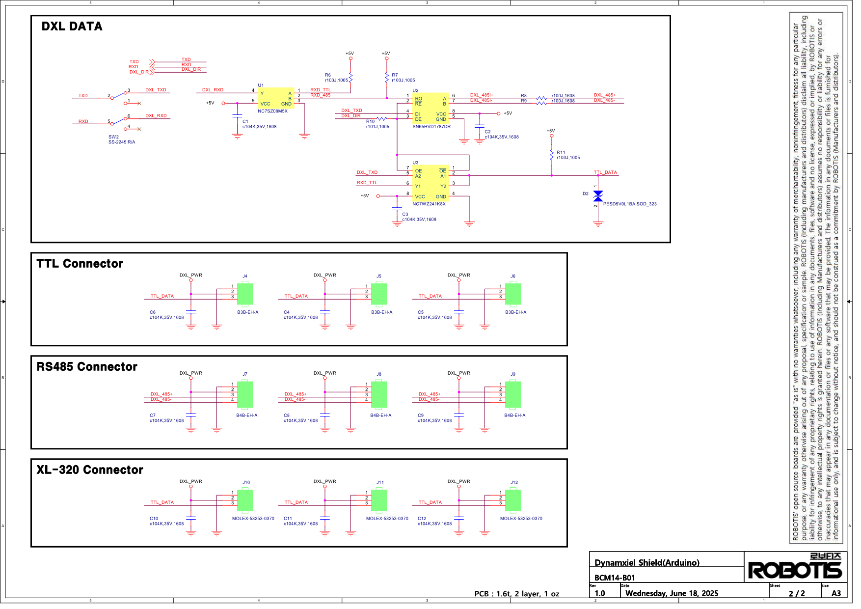
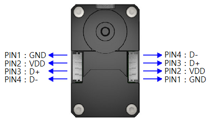
DYNAMIXEL Connectors
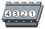
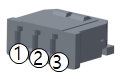
| Item | TTL | RS-485 | XL-320 (TTL) |
|---|---|---|---|
| Pinout | 1 GND2 VDD3 DATA |
1 GND2 VDD3 DATA+4 DATA- |
1 GND2 VDD3 DATA |
| Diagram |  |
 |
 |
| Housing | 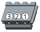 JST EHR-03 |
 JST EHR-04 |
 MOLEX 51065-0300 |
| PCB Header | 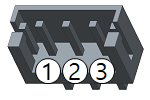 JST B3B-EH-A |
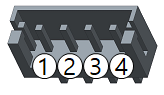 JST B4B-EH-A |
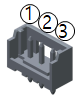 MOLEX 53253-0370 |
| Crimp Terminal | JST SEH-001T-P0.6 | JST SEH-001T-P0.6 | MOLEX 50212-8000 |
| Wire Gauge for DYNAMIXEL | 21 AWG | 21 AWG | 24 AWG |
Communication Circuit
To control the DYNAMIXEL actuators, the main controller needs to convert its UART signals to the half duplex type. The recommended circuit diagram for this is shown below.
TTL Communication
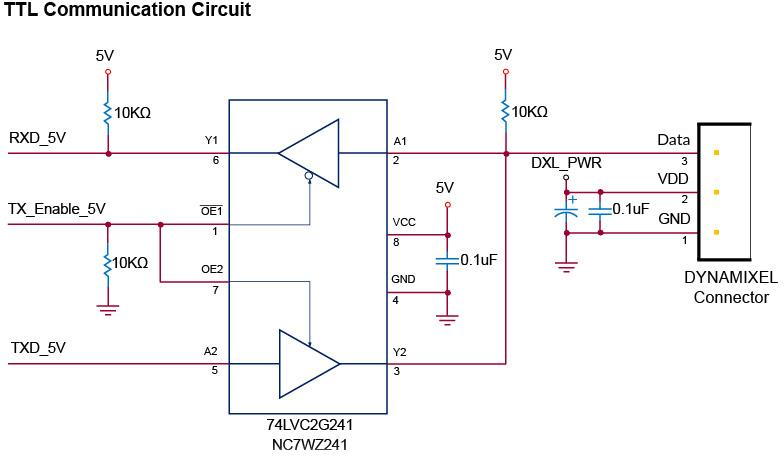
TTL Circuit
NOTE: Above circuit is designed for 5V or 5V tolerant MCU. Otherwise, use a Level Shifter to match the voltage of MCU.
RS-485 Communication
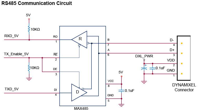
RS-485 Circuit
NOTE: Above circuit is designed for 5V or 5V tolerant MCU. Otherwise, use a Level Shifter to match the voltage of MCU.
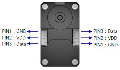
The power of DYNAMIXEL is supplied via Pin1(-), Pin2(+).
(The above circuit is built into DYNAMIXEL’s controller only)
In the above circuit diagram, the direction of data signal of TxD and RxD in the TTL Level is determined according to the level of DIRECTION 485 as follows:
In case of DIRECTION485 Level = High: The signal of TxD is output to D+ and D-
In case of DIRECTION485 Level = Low: The signal of D+ and D- is output to RxD