
Introduction
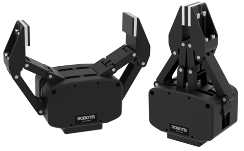
RH-P12-RN(A)
RH-P12-RN(A)
- It uses improved firmware version compared to RH-P12-RN.
- It has the similar control table structure to DYNAMIXEL-PRO(A) and DYNAMIXEL-P series, so that they can be used together.
RH-P12-RN
- It uses old firmware version.
- It has the similar control table structure to DYNAMIXEL-PRO series, so that they can be used together.
- More information is available at RH-P12-RN manual.
You can choose the desired firmware version by using Firmware Recovery of R+Manager 2.0 or DYNAMIXEL Wizard 2.0
NOTE : As DYNAMIXEL-PRO series is discontinued, using RH-P12-RN(A) Firmware version is recommended.
Hardware Revision History
| Rev | Image | Stroke | Date |
|---|---|---|---|
| 0 | 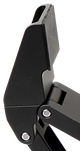 |
0 ~ 109 mm | . |
| 1 | 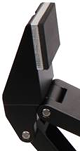 |
0 ~ 106 mm | Nov 04th, 2019 |
Specifications
| Item | Specifications |
|---|---|
| MCU | ST CORTEX-M4 (STM32F405 @ 168 Mhz, 32 bit) |
| Position Sensor | Contactless Absolute Encoder (12 bit, 360°) Maker : ams(www.ams.com), Part No : AS5045 |
| Motor | Coreless |
| Baud Rate | 9,600 bps ~ 10.5 Mbps |
| Control Algorithm | PID Control |
| Degree of Precision | 0.088° |
| Operating Mode | Current Control Mode Current based Position Control Mode |
| Weight | 500 g |
| Stroke | 0 ~ 106 mm |
| Max Closing Speed | 75 mm/s |
| Gear Ratio | 1181 : 1 |
| Maximum Gripping Force | 170 N |
| Recommended Payload | 5 kg |
| Operating Temperature | -5°C ~ 55°C |
| Nominal Voltage | 24 V |
| Command Signal | Digital Packet |
| Protocol Type | RS485 Asynchronous Serial Communication (8bit, 1stop, No Parity) |
| Physical Connection | RS485 Multidrop Bus |
| ID | 0 ~ 252 |
| Feedback | Position, Velocity, Current, Temperature, Input Voltage, etc |
| Material | Full Metal Gear, Metal Body |
| Standby Current | 30 mA |
| Peak Current | 3.33 A |
![]()
DANGER
(Ignoring these warnings may cause serious injury or death)
- Never place items containing water, flammables/open flames, or solvents near the product.
- Never place fingers, arms, toes, and other body parts near product during operation.
- Cease operation and remove power from the product if the product begins to emit strange odors, noises, or smoke.
- Keep product out of reach of children.
- Check input polarity before installing or energizing wiring or cables.
![]()
CAUTION
(Ignoring these warnings may cause mild injury or damage to the product)
- Always comply with the product’s offical operating environment specifications including input voltage, current, and operating temperature.
- Do not insert blades or other sharp objects during product operation.
![]()
ATTENTION
(Ignoring these warnings may cause minor injury or damage to the product)
- Do not disassemble or modify the product.
- Do not drop the product or apply strong impacts.
- Do not connect or disconnect DYNAMIXEL cables while power is being supplied.
Control Table
The Control Table is a data structure used by DYNAMIXEL actuators to manage the state of the device. Users can read data registers to get information about the status of the device with Read Instruction Packets, and modify data registers to control the device with Write Instruction Packets.
WARNING : RH-P12-RN(A) uses different Control Table from RH-P12-RN. Please pay attention when upgrading RH-P12-RN to RH-P12-RN(A).
Control Table, Data, Address
The Control Table is a structure that consists of multiple Data fields to store status or to control the device. Users can check current status of the device by reading a specific Data from the Control Table with Read Instruction Packets. WRITE Instruction Packets enable users to control the device by changing specific Data in the Control Table. The Address is a unique value when accessing a specific Data in the Control Table with Instruction Packets. In order to read or write data, users must designate a specific Address in the Instruction Packet. Please refer to DYNAMIXEL Protocol 2.0 for more details about Instruction Packets.
NOTE : Two’s complement is applied for the negative value. For more information, please refer to Two’s complement from Wikipedia.
Area (EEPROM, RAM)
The Control Table is divided into 2 Areas. Data in the RAM Area is reset to initial values when the power is reset(Volatile). On the other hand, data in the EEPROM Area is maintained even when the device is powered off(Non-Volatile).
Data in the EEPROM Area can only be written to if Torque Enable(512) is cleared to ‘0’(Torque OFF).
Size
The Size of data varies from 1 ~ 4 bytes depend on their usage. Please check the size of data when updating the data with an Instruction Packet. For data larger than 2 bytes will be saved according to Little Endian.
Access
The Control Table has two different access properties. ‘RW’ property stands for read and write access permission while ‘R’ stands for read only access permission. Data with the read only property cannot be changed by the WRITE Instruction. Read only property(‘R’) is generally used for measuring and monitoring purpose, and read write property(‘RW’) is used for controlling device.
Initial Value
Each data in the Control Table is restored to initial values when the device is turned on. Default values in the EEPROM area are initial values of the device (factory default settings). If any values in the EEPROM area are modified by a user, modified values will be restored as initial values when the device is turned on. Initial Values in the RAM area are restored when the device is turned on.
Control Table of EEPROM Area
| Address | Size(Byte) | Modbus Address |
Data Name | Access | Initial Value |
Range | Unit |
|---|---|---|---|---|---|---|---|
| 0 | 2 | 40001 | Model Number | R | 35,074 | - | - |
| 2 | 4 | 40002 | Model Information | R | - | - | - |
| 6 | 1 | 40004 (Lo Byte) | Firmware Version | R | - | - | - |
| 7 | 1 | 40004 (Hi Byte) | ID | RW | 1 | 0 ~ 252 | - |
| 8 | 1 | 40005 (Lo Byte) | Baud Rate | RW | 1 | 0 ~ 9 | - |
| 9 | 1 | N/A | Return Delay Time | RW | 250 | 0 ~ 255 | 2 [μsec] |
| 11 | 1 | 40006 (Hi Byte) | Operating Mode | RW | 5 | 0, 5 | - |
| 12 | 1 | N/A | Secondary ID | RW | 255 | 0 ~ 255 | - |
| 13 | 1 | 40007 (Hi Byte) | Protocol Type | RW | 2 | 2, 10 | - |
| 20 | 4 | 40011 | Homing Offset | RW | 0 | 0 ~ 1,150 | 1 [pulse] |
| 24 | 4 | 40013 | Moving Threshold | RW | 80 | 0 ~ 2,970 | 0.01 [rev/min] |
| 31 | 1 | 40016 (Hi Byte) | Temperature Limit | RW | 80 | 0 ~ 100 | 1 [°C] |
| 32 | 2 | 40017 | Max Voltage Limit | RW | 300 | 150 ~ 300 | 0.1 [V] |
| 34 | 2 | 40018 | Min Voltage Limit | RW | 150 | 150 ~ 300 | 0.1 [V] |
| 36 | 2 | 40019 | PWM Limit | RW | 2,009 | 0 ~ 2,009 | 0.0498 [%] |
| 38 | 2 | 40020 | Current Limit | RW | 661 | 0 ~ 1,984 | 1 [mA] |
| 40 | 4 | 40021 | Acceleration Limit | RW | 3,447 | 0 ~ 1,378,788 | 1 [rev/min2] |
| 44 | 4 | 40023 | Velocity Limit | RW | 2,970 | 0 ~ 2,970 | 0.01 [rev/min] |
| 48 | 4 | 40025 | Max Position Limit | RW | 1,150 | 0 ~ 1,150 | 1 [pulse] |
| 52 | 4 | 40027 | Min Position Limit | RW | 0 | 0 ~ 1,150 | 1 [pulse] |
| 56 | 1 | 40029 (Lo Byte) | External Port Mode 1 | RW | 3 | 0 ~ 3 | - |
| 57 | 1 | 40029 (Hi Byte) | External Port Mode 2 | RW | 3 | 0 ~ 3 | - |
| 58 | 1 | 40030 (Lo Byte) | External Port Mode 3 | RW | 3 | 0 ~ 3 | - |
| 59 | 1 | 40030 (Hi Byte) | External Port Mode 4 | RW | 3 | 0 ~ 3 | - |
| 63 | 1 | 40032 (Hi Byte) | Shutdown | RW | 58 | 0x20(Overload) 0x10(Electrical Shock) 0x08(Motor Encoder) 0x04(Overheating) 0x02(Motor Hall Sensor) 0x01(Input Voltagae) |
- |
| 168 | 2 | N/A | Indirect Address 1 | RW | 634 | 512 ~ 1,023 | - |
| 170 | 2 | N/A | Indirect Address 2 | RW | 635 | 512 ~ 1,023 | - |
| 172 | 2 | N/A | Indirect Address 3 | RW | 636 | 512 ~ 1,023 | - |
| … | … | … | … | … | … | … | … |
| 422 | 2 | N/A | Indirect Address 128 | RW | 761 | 512 ~ 1,023 | - |
Control Table of RAM Area
| Address | Size(Byte) | Modbus Address |
Data Name | Access | Initial Value |
Range | Unit |
|---|---|---|---|---|---|---|---|
| 512 | 1 | 40257 (Lo Byte) | Torque Enable | RW | 0 | 0 ~ 1 | - |
| 513 | 1 | 40257 (Hi Byte) | LED Red | RW | 0 | 0 ~ 255 | - |
| 514 | 1 | 40258 (Lo Byte) | LED Green | RW | 0 | 0 ~ 255 | - |
| 515 | 1 | 40258 (Hi Byte) | LED Blue | RW | 0 | 0 ~ 255 | - |
| 516 | 1 | N/A | Status Return Level | RW | 2 | 0 ~ 2 | - |
| 517 | 1 | N/A | Registered Instruction | R | 0 | - | - |
| 518 | 1 | 40260 (Lo Byte) | Hardware Error Status | R | 0 | - | - |
| 524 | 2 | 40263 | Velocity I Gain | RW | - | 0 ~ 32,767 | - |
| 526 | 2 | 40264 | Velocity P Gain | RW | - | 0 ~ 32,767 | - |
| 528 | 2 | 40265 | Position D Gain | RW | - | 0 ~ 32,767 | - |
| 532 | 2 | 40266 | Position P Gain | RW | - | 0 ~ 32,767 | - |
| 530 | 2 | 40267 | Position I Gain | RW | - | 0 ~ 32,767 | - |
| 536 | 2 | 40269 | Feedforward 2nd Gain | RW | - | 0 ~ 32,767 | - |
| 538 | 2 | 40270 | Feedforward 1st Gain | RW | - | 0 ~ 32,767 | - |
| 546 | 1 | 40274 (Lo Byte) | Bus Watchdog | RW | - | 0 ~ 127 | 20 [msec] |
| 548 | 2 | 40275 | Goal PWM | RW | - | -PWM Limit(36) ~ PWM Limit(36) |
0.0498 [%] |
| 550 | 2 | 40276 | Goal Current | RW | 0 | -Current Limit(38) ~ Current Limit(38) |
1 [mA] |
| 552 | 4 | 40277 | Goal Velocity | RW | 0 | -Velocity Limit(44) ~ Velocity Limit(44) |
0.01 [rev/min] |
| 556 | 4 | 40279 | Profile Acceleration | RW | 0 | 0 ~ Acceleration Limit(40) |
1 [rev/min2] |
| 560 | 4 | 40281 | Profile Velocity | RW | 0 | 0 ~ Velocity Limit(44) |
0.01 [rev/min] |
| 564 | 4 | 40283 | Goal Position | RW | - | Min Position Limit(52) ~ Max Position Limit(48) |
1[pulse] |
| 568 | 2 | 40285 | Realtime Tick | R | - | 0 ~ 32,767 | 1 [msec] |
| 570 | 1 | 40286 (Lo Byte) | Moving | R | - | - | - |
| 571 | 1 | 40286 (Hi Byte) | Moving Status | R | - | - | - |
| 572 | 2 | 40287 | Present PWM | R | - | - | 0.0498 [%] |
| 574 | 2 | 40288 | Present Current | R | - | - | 1 [mA] |
| 576 | 4 | 40289 | Present Velocity | R | - | - | 0.01 [rev/min] |
| 580 | 4 | 40291 | Present Position | R | - | - | 1 [pulse] |
| 584 | 4 | 40293 | Velocity Trajectory | R | - | - | 0.01 [rev/min] |
| 588 | 4 | 40295 | Position Trajectory | R | - | - | 1 [pulse] |
| 592 | 2 | 40297 | Present Input Voltage | R | - | - | 0.1 [V] |
| 594 | 1 | 40298 (Lo Byte) | Present Temperature | R | - | - | 1 [°C] |
| 600 | 2 | 40301 | External Port Data 1 | R/RW | 0 | 0 ~ 4,095 | - |
| 602 | 2 | 40302 | External Port Data 2 | R/RW | 0 | 0 ~ 4,095 | - |
| 604 | 2 | 40303 | External Port Data 3 | R/RW | 0 | 0 ~ 4,095 | - |
| 606 | 2 | 40304 | External Port Data 4 | R/RW | 0 | 0 ~ 4,095 | - |
| 634 | 1 | N/A | Indirect Data 1 | RW | 0 | 0 ~ 255 | - |
| 635 | 1 | N/A | Indirect Data 2 | RW | 0 | 0 ~ 255 | - |
| 636 | 1 | N/A | Indirect Data 3 | RW | 0 | 0 ~ 255 | - |
| … | … | … | … | … | … | … | |
| 761 | 1 | N/A | Indirect Data 128 | RW | 0 | 0 ~ 255 | - |
Control Table Description
CAUTION : Data in the EEPROM Area can only be written when the value of Torque Enable(512) is cleared to 0.
NOTE : RH-P12-RN(A) stands for the Advanced firmware of RH-P12-RN. Please be aware of the changes of Control Table such as Addresses and additional features.
Model Number(0)
This address stores model number of the device.
| Model Name | Model Number |
|---|---|
| RH-P12-RN(A) | 35,074 (0x8902) |
Firmware Version(6)
This address stores firmware version of the device.
ID(7)
The DYNAMIXEL ID is used by the DYNAMIXEL network to identify individual actuators for instruction packets. Values between 0 and 253 (0xFD) can be assigned to individual DYNAMIXEL actuators and address 254(0xFE) is is reserved for the global broadcast ID to send instruction packets to all connected devices simultaneously.
NOTE: DYNAMIXEL IDs must be unique for each device connected to a DYNAMIXEL network. Multiple devices sharing a single ID may cause communications issues or control failure.
Baud Rate(8)
The Baud Rate setting determines the serial communication speed between your controller and DYNAMIXEL actuators.
| Value | Baud Rate | Actual Baud Rate | Margin of Error |
|---|---|---|---|
| 9 | 10.5M [bps] | 10,500,000 | 0.000% |
| 8 | 6M [bps] | 6,000,000 | 0.000% |
| 7 | 4.5M [bps] | 4,421,053 | -1.176% |
| 6 | 4M [bps] | 4,000,000 | 0.000% |
| 5 | 3M [bps] | 3,000,000 | 0.000% |
| 4 | 2M [bps] | 2,000,000 | 0.000% |
| 3 | 1M [bps] | 1,000,000 | 0.000% |
| 2 | 115,200 [bps] | 115,226 | 0.023% |
| 1(Default) | 57,600 [bps] | 57,613 | 0.023% |
| 0 | 9,600 [bps] | 9,600 | 0.000% |
NOTE: UART communications will remain stable with a margin of error of up to 3%.
NOTE: For stable high speed communication over USB serial connections, you may need to adjust the USB latency settings in your PC’s settings.
Return Delay Time(9)
Following the receipt of an instruction packet, a DYNAMIXEL servo will return a status packet after the configured Return Delay Time(9) has elapsed.
The range of acceptable values includes 0 to 254 (0XFE) with each unit representing a 2μsec delay. For example, if Return Delay Time(9) is set to ‘10’, a status packet will be returned after a 20μsec delay when an instruction packet is received.
| Unit | Value Range | Description |
|---|---|---|
| 2μsec | 0 ~ 254 | Default Value: ‘250’(500 [μs]) Maximum Value: 508 [μs] |
WARNING : Modbus-RTU communication does not support the Return Delay Time(9) feature.
Operating Mode(11)
Operating mode of the device can be configured. Each control mode has different characteristics so please choose appropriate mode for the application.
| Value | Operating Mode | Description |
|---|---|---|
| 0 | Current Control Mode | This mode only controls Current regardless of speed and position. |
| 1 ~ 4 | Reserved | - |
| 5(Default) | Current based Position Control Mode | This mode controls both Position and Current. |
Secondary ID(12)
Configure the secondary ID of your DYNAMIXEL servo.
Unlike the primary ID(7) overlapping Secondary ID(12) settings are allowed, allowing simple synchronization of multiple DYNAMIXEL actuators.
The primary and secondary IDs differ in several ways.
- Secondary ID(12) do not need to be unique, and can be shared among any number of DYNAMIXEL servos.
- The primary ID(7) has a greater priority than the Secondary ID(12). If the Secondary ID(12) and primary ID(7) are the same, the servo will act as if the instruction has been sent only to it’s primary ID.
- The EEPROM area of the Control Table cannot be modified using Secondary ID(12), changes can only be made to the RAM area when addressed to secondary IDs.
- Status packets will not be returned for instructions sent to secondary IDs.
- The secondary ID function is completely disabled when it has been set to a value higher than 253.
| Values | Description |
|---|---|
| 0 ~ 252 | Enable the secondary ID feature with the configured ID value. |
| 253 ~ 255 | Deactivate the Secondary ID function. The Default value of the setting is ‘255’. |
The following example showcases some of the functionality of DYNAMIXEL’s secondary ID function using DYNAMIXELs with primary ID’s from 1-5:
- Set all five devices’ Secondary ID(12) to ‘5’.
- Send a Write Instruction Packet to ID 1 turning on the LED: LED Red(513) = 255.
- DYNAMIXEL ID 1’s LED will illuminate, and a status packet will be returned.
- Send a Write Instruction Packet to ID 5 turning on the LED: LED Red(513) = 255.
- The LEDs of all five devices will turn on, but a status packet will only be returned from DYNAMIXEL ID 5.
- Set the Secondary ID(12) of all five devices to ‘100’.
- Send a Write Instruction Packet to ID 100: LED Red(513) = 0.
- The LEDs of all five devices will turn off, but no status packet will be returned as there is no device with primary ID 100.
WARNING : Modbus-RTU communication does not support Secondary ID(12) functionality.
Protocol Type(13)
Select the active communications protocol for your DYNAMIXEL actuator. In order to use Modbus-RTU on your RH-P12-RN(A) servo you must update to firmware version V12 or higher.
| Value | Description |
|---|---|
| 2 | DYNAMIXEL Protocol 2.0 |
| 10 | Modbus-RTU, Industrial Standard Protocol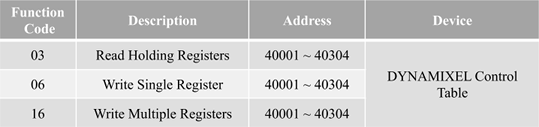 |
WARNING: DYNAMIXEL Wizard 2.0 is required to change the communications protocol of your DYNAMIXEL servo, as R+ Manager 2.0 does not support Modbus-RTU communication.
WARNING : The following Control Table items are not supported by Modbus-RTU communications.
Return Delay Time(9)
Secondary ID(12)
Status Return Level(516)
Registered Instruction(517)
Indirect Address
Indirect Data
Homing Offset(20)
Users can adjust the Home position by setting Home Offset(20). The Homing Offset value is added to the Present Position(580).
Present Position(580) = Actual Position + Homing Offset(20).
| Unit | Value Range |
|---|---|
| 1 [pulse] | 0 ~ 1150 |
Moving Threshold(24)
This value determines whether the device is in motion or not.
When the absolute value of Present Velocity(576) is greater than this value, Moving(570) is set to 1, otherwise it is cleared to 0.
| Unit | Value Range |
|---|---|
| 0.01 [rev/min] | 0 ~ 2,970 |
Temperature Limit(31)
This value limits operating temperature.
When the Present Temperature(594) that indicates internal temperature of device is greater than the Temperature Limit(31), the Overheating Error Bit(0x04) in the Hardware Error Status(518) will be set.
If Overheating Error Bit(0x04) is configured in the Shutdown(63), Torque Enable(512) will be set to ‘0’ (Torque OFF).
For more details, please refer to the Shutdown(63) section.
| Unit | Value Range | Description |
|---|---|---|
| About 1 [°C] | 0 ~ 100 | 0 ~ 100 [°C] |
CAUTION : Do not set the temperature lower/higher than the default value. When the temperature alarm shutdown occurs, wait for 20 minutes to cool the temperature before reuse. Keep using the product with high temperature can cause severe damage to the device.
Max/Min Voltage Limit(32, 34)
These values are maximum and minimum operating voltages.
When the Present Input Voltage(592) exceeds the range of Max Voltage Limit(32) and Min Voltage Limit(34), Input Voltage Error Bit(0x01) is set in the Hardware Error Status(518) and Alert Bit(0x80) is set in the Error field of the Status Packet.
If Input Voltage Error Bit(0x10) is configured in the Shutdown(63), Torque Enable(512) will be set to ‘0’ (Torque OFF). For more details, please refer to the Shutdown(63) section.
| Unit | Value Range |
|---|---|
| about 0.1 [V] | 150 ~ 300 |
PWM Limit(36)
This value indicates the maximum PWM output.
Goal PWM(548) cannot be configured with any values exceeding PWM Limit(36).
PWM Limit(36) is commonly applied in all operating mode as an output limit, therefore decreasing PWM output will also decrease torque and velocity of the device.
For more details, please refer to the Gain section of each operating mode.
| Value | Description |
|---|---|
| 0 ~ 2,009 | 2,009 = 100 [%] Output |
Current Limit(38)
This value indicates the maximum current(torque) output limit.
Goal Current(550) cannot be configured with any values exceeding Current Limit(38). Attempting to write an invalid value will fail and set the Limit Error Bit in the error field of the Status Packet.
| Unit | Value Range |
|---|---|
| 1 [mA] | 0 ~ 1,984 |
Acceleration Limit(40)
This value indicates the maximum acceleration limit.
Profile Acceleration(556) cannot be configured with any values exceeding Acceleration Limit(40). Attempting to write an invalid value will fail and set the Limit Error Bit in the error field of the Status Packet.
| Unit | Value Range |
|---|---|
| 1 [rev/min2] | 0 ~ 1,378,788 |
Velocity Limit(44)
This value indicates maximum velocity of Goal Velocity(552) and Profile Velocity(560). Goal Velocity(552) and Profile Velocity(562) cannot be configured with any values exceeding Velocity Limit(44). Attempting to write an invalid value will fail and set the Limit Error Bit in the error field of the Status Packet.
| Unit | Value Range |
|---|---|
| 0.01 [rev/min] | 0 ~ 2,970 |
Max/Min Position Limit(48, 52)
These values limit maximum and minimum positions in Current based Position Control Mode within the range of 0 ~ 1,150.
Therefore, Goal Position(564) should not exceed the limit range. Attempting to write an invalid value will fail and set the Limit Error Bit in the error field of the Status Packet.
| Unit | Value Range |
|---|---|
| 1 [pulse] | 0 ~ 1,150 |
External Port Mode, External Port Data
External ports that can be used for various purposes are provided.
The property of each port is configured by the External Port Mode (56 ~ 59) and data of external port is controlled by the External Port Data(600 ~ 607).
The signal of External Port can be controlled or checked via External Port Data.
The External Port is not electrically insulated, therefore, abide by the electrical specifications.
Shielded cable or twisted paired cable reduces signal noise and error.
Shorter cable increases accuracy of the measurement.
| Item | Description |
|---|---|
| Voltage | 0 ~ 3.3 [V] VESD(HBM) : 2[kV] |
| Current | 0 ~ 5 [mA] |
※ VESD(HBM) : ESD(Electrostatic Discharge) Voltage(human body model)
| Function | External Port Mode | External Port Data | Access | Details |
|---|---|---|---|---|
| Analogue Input | 0 | Converts External Port signal to digital value External Data = signal x (4,095 / 3.3) |
R | Resolution : 12[bit] (0 ~ 4,095) |
| Digital Output Push-Pull | 1 | 0 : Set External Port output to 0[V] 1 : Set External Port output to 3.3[V] |
W | Output High level(VOH) : 2.4 [V] (min) Output Low level(VOL) : 0.5 [V] (max) |
| Digital Input Pull-Up | 2 | 0 : External Port input is 0[V] 1 : External Port input is 3.3[V] or Open |
R | Input High level(VIH) : 2.3 [V] (min) Input Low level(VIL) : 1.0 [V] (max) Pull-Up : 40 [kΩ] (typ) |
| Digital Input Pull-Down | 3 (Default) | 0 : External Port input is 0[V] or Open 1 : External Port input is 3.3[V] |
R | Input High level(VIH) : 2.3 [V] (min) Input Low level(VIL) : 1.0 [V] (max) Pull-Down : 40 [kΩ] (typ) |
WARNING : The External Port is not electrically insulated, therefore, abide by the electrical specifications.
If the electrical specification is exceeded or there is a problem with the signal connection, special caution is required because DYNAMIXEL can be damaged.
- Be careful not to cause electric shock by static electricity (ESD), short circuit, open circuit.
- Be careful not to let water or dust get into the External Port connector.
- If you are not using the External Port, remove the cable.
- To connect or disconnect the External Port, proceed with power off.
- Do not connect the GNDext pin of External Port directly to the GND pin of DYNAMIXEL connector. Noise from power may affect on the External Port.
External expansion port location and pin function
Remove bolts and cover plate to reveal External Port connector.
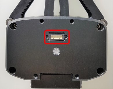
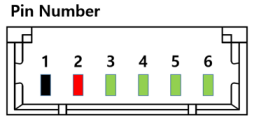
| Pin 1 | Pin 2 | Pin 3 | Pin 4 | Pin 5 | Pin 6 |
|---|---|---|---|---|---|
| GND | 3.3V | PORT1 | PORT2 | PORT3 | PORT4 |
Shutdown(63)
The DYNAMIXEL can protect itself by detecting dangerous situations that could occur during the operation. Each Bit is inclusively processed with the ‘OR’ logic, therefore, multiple options can be generated. For instance, when ‘0x05’ (binary : 00000101) is defined in Shutdown(63), DYNAMIXEL can detect both Input Voltage Error(binary : 00000001) and Overheating Error(binary : 00000100). If those errors are detected, Torque Enable(64) is cleared to ‘0’ and the motor’s output becomes 0 [%].
REBOOT is the only method to reset Torque Enable(64) to ‘1’(Torque ON) after the shutdown.
Check Alert Bit(0x80) in an error field of Status Packet or a present status via Hardware Error Status(70). The followings are detectable situations.
| Bit | Item | Description | |
|---|---|---|---|
| Bit 7 | - | Unused, Always ‘0’ | |
| Bit 6 | - | Unused, Always ‘0’ | |
| Bit 5 | Overload Error(default) | Detects that persistent load that exceeds maximum output | |
| Bit 4 | Electrical Shock Error(default) | Detects electric shock on the circuit or insufficient power to operate the motor | |
| Bit 3 | Motor Encoder Error | Detects malfunction of the motor encoder | |
| Bit 2 | Overheating Error(default) | Detects that internal temperature exceeds the configured operating temperature | |
| Bit 1 | - | Unused, Always ‘0’ | |
| Bit 0 | Input Voltage Error | Detects that input voltage exceeds the configured operating voltage |
NOTE :
- If Shutdown occurs, LED will flicker every second. (Firmware v41 or above)
- If Shutdown occurs, reboot the device.
- H/W REBOOT : Turn off and turn on the power again
- S/W REBOOT : Transmit REBOOT Instruction (For more details, refer to the Reboot section of e-Manual.)
Indirect Address, Indirect Data
Indirect Address and Indirect Data are useful when accessing multiple remote addresses in the Control Table as sequential addresses. Sequential address increases the efficiency of Instruction Packet. Addresses that can be defined as Indirect Address are limited to RAM area(Address 512 ~ 606).
If specific address is allocated to Indirect Address, Indirect Address inherits features and properties of the Data from the specific Address. Property includes Size(Byte length), value range, and Access property(Read Only, Read/Write).
For instance, allocating 513(which is the Address of red LED) to Indirect Address 1(168) and writing 255 to the Indirect Data 1(634) will turn on the red LED. The actual value of LED Red(513) will also be set as 255.
If a specific item has address longer than 2 byte, each address byte has to be sequentially configured in the Indirect Address.
Example 1 : Allocating 1 byte LED Red(513) to Indirect Data 1(634).
- Indirect Address 1(168) : write
513which is the address of LED Red. - Set Indirect Data 1(634) to
255: The value of LED Red(513) will automatically set as255and LED will be turned on. - Set Indirect Data 1(634) to
0: The value of LED Red(513) will automatically set as0and LED will be turned off.
Example 2 : To allocate 4 byte Goal Position(564) to Indirect Data 2(635), 4 sequential bytes have to be allocated.
- Indirect Address 2(170) : Write
564which is the first address of Goal Position. - Indirect Address 3(172) : Write
565which is the second address of Goal Position. - Indirect Address 4(174) : Write
566which is the third address of Goal Position. - Indirect Address 5(176) : Write
567which is the fourth address of Goal Position. - Write 4 byte desired position value of 250,961(0x0003D451) to Indirect Data 2 ~ 5 : The value of Goal Position(564) will reflect these changes and set as 0x0003D451 as shown below(Little Endian).
| Indirect Data Address | Goal Position Address | Saved HEX Value |
|---|---|---|
| 635 | 564 | 0x51 |
| 636 | 565 | 0xD4 |
| 637 | 566 | 0x03 |
| 638 | 567 | 0x00 |
NOTE : In order to allocate Data in the Control Table longer than 2[byte] to Indirect Address, all address must be allocated to Indirect Address like the above Example 2.
WARNING : Modebus-RTU dose not support Indirect Address and Indirect Data.
Torque Enable(512)
Torque Enable(64) determines Torque ON/OFF. Writing ‘1’ to Torque Enable’s address will turn on the Torque and all Data in the EEPROM area will be locked.
| Value | Description |
|---|---|
| 0(Default) | Torque Off |
| 1 | Torque On and lock EEPROM area |
NOTE : Present Position(580) can be reset when Operating Mode(11) and Torque Enable(512) are updated. For more details, please refer to the Homing Offset(20) and Present Position(580).
RGB LED
These addresses control the RGB LED of the device. When Shutdown occurs, LED cannot be controlled.
| Address | Color | Range |
|---|---|---|
| 513 | Red | 0 ~ 255 |
| 514 | Green | 0 ~ 255 |
| 515 | Blue | 0 ~ 255 |
Status Return Level(516)
This value decides how to return Status Packet when the device receives an Instruction Packet.
| Value | Responding Instructions | Description |
|---|---|---|
| 0 | PING Instruction | Returns the Status Packet for PING Instruction only |
| 1 | PING Instruction READ Instruction |
Returns the Status Packet for PING and READ Instruction |
| 2 | All Instructions | Returns the Status Packet for all Instructions |
NOTE : If the Instruction Packet ID is set to the Broadcast ID(0xFE), Status Packet will not be returned for READ and WRITE Instructions regardless of Status Return Level(516). For more details, please refer to the Status Packet section of Protocol 2.0.
WARNING : Modebus-RTU dose not support Status Return Level(516).
Registered Instruction(517)
| Value | Description |
|---|---|
| 0 | No instruction registered by REG_WRITE. |
| 1 | Instruction registered by REG_WRITE exists. |
NOTE : If ACTION instruction is executed, the Registered Instruction(517) will be changed to 0.
WARNING : Modebus-RTU dose not support Registered Instruction(517).
Hardware Error Status(518)
This value indicates hardware error status. For more details, please refer to Shutdown(63) section.
Velocity PI Gain(524, 526), Position PID Gain(528,530,532), Feedforward 2nd Gains(536), Feedforward 1st Gains(538)
These values indicate Gains of Current based Position Control. Position P Gain of the device’s internal controller is abbreviated to KPP and that of the Control Table is abbreviated to KPP(TBL).
| Controller Gain | Range | Description | |
|---|---|---|---|
| Velocity I Gain(524) | KVI | 0 ~ 32,767 | Velocity Integral Gain |
| Velocity P Gain(526) | KVP | 0 ~ 32,767 | Velocity Proportion Gain |
| Position D Gain(528) | KPD | 0 ~ 32,767 | Position Differential Gain |
| Position I Gain(530) | KPI | 0 ~ 32,767 | Position Integral Gain |
| Position P Gain(532) | KPP | 0 ~ 32,767 | Position Proportion Gain |
| Feedforward 2nd Gain(536) | KFF1st | 0 ~ 32,767 | Feedforward Acceleration Gain |
| Feedforward 1st Gain(538) | KFF1st | 0 ~ 32,767 | Feedforward Velocity Gain |
Below figure is a block diagram describing the position controller in Current-based Position Control Mode. When the instruction is received by the device, it takes following steps until driving the device.
- An Instruction from the user is transmitted via communication bus, then registered to Goal Position(564).
- Goal Position(564) is converted to desired Position Trajectory and Velocity Trajectory by Profile Acceleration(556).
- The desired Velocity Trajectory and Position Trajectory are stored at Velocity Trajectory(584) and Position Trajectory(588).
- Feedforward and PID controller calculates PWM output for the motor based on the desired trajectories.
- Goal PWM(584) sets a limit on the calculated PWM output and decides the final PWM value.
- The final PWM value is applied to the motor through an Inverter, and the device is driven.
- Results are stored at Present Position(580), Present Velocity(576), Present PWM(572) and Present Current(574).
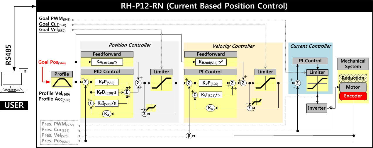
NOTE : Ka stands for Anti-windup Gain that cannot be modified by users.
Bus Watchdog(546)
Bus Watchdog(546) is a safety feature(Fail-safe) that stops the device if the communication(RS-485, TTL) between the controller and the device is disconnected due to an unidentified error.
The “communication” can be seen as all the Instruction Packets defined in the protocol.
| Value | Description | |
|---|---|---|
| Range | 0 | Deactivates Bus Watchdog Function and clears Bus Watchdog Error |
| Range | 1 ~ 127 | Activates Bus Watchdog (Unit: 20 [msec]) |
| Range | -1 | Bus Watchdog Error Status |
The Bus Watchdog monitors the communication interval time between the controller and the device when Torque Enable(512) is ‘1’ (Torque ON).
If the measured communication interval time is longer than set value of Bus Watchdog(546), the device will be stopped and Bus Watchdog(546) value will be set to ‘-1’ (Bus Watchdog Error).
If Bus Watchdog Error occurs, goal values such as Goal PWM(548), Goal Current(550), Goal Velocity(552) and Goal Position(564) will be changed to read-only-access.
Therefore, if a new value is written to the Goal Value, the Status Packet will send the Data Range Error via its Error field.
Writing ‘0’ to Bus Watchdog(546) will clear the Bus Watchdog Error.
NOTE : For details of Data Range Error, please refer to the Protocol 2.0.
The following is the example of Bus Watchdog function.
- After setting the Operating Mode(11) to Velocity Control Mode, change the Torque Enable(512) to
1. - If
50is written to the Goal Velocity(552), the device will rotate in CCW direction. - Change the value of Bus Watchdog(546) to
100(2,000 [ms]). (Activate Bus Watchdog Function) - If no instruction packet is received within 2,000 [ms], the device will stop with the predefined decelerating value.
- Bus Watchdog(546) value is set to
-1(Bus Watchdog Error). At this time, the access property of goal values will be changed to read-only. - If
150is written to the Goal Velocity(552), the Data Range Error will be returned via Status Packet. - If Bus Watchdog(546) value is changed to
0, Bus Watchdog Error will be cleared. - If
150is written in the Goal Velocity(552), the device will rotate in CCW direction.
Goal PWM(548)
Goal PWM(548) cannot exceed PWM Limit(36) and is used to limit the output power.
Please refer to the Gain section in order to see how Goal PWM(548) affects to internal controller.
| Unit | Range |
|---|---|
| about 0.0498 [%] | -PWM Limit(36) ~ PWM Limit(36) |
Goal Current(550)
In Current Control Mode, Goal Current(550) can be used to set the desired current. This value sets a current limit of the current controller in Current-based Position Control Mode. This value cannot exceed Current Limit(38).
Goal Velocity(552)
Goal Velocity(552) value is used as an input limiter of velocity controller.
This value cannot exceed Velocity Limit(44).
Profile Acceleration(556)
Profile Acceleration is set with this value.
This value is used only in Current-based Position Control Mode.
The value of Profile Acceleration ranges from 0 to Acceleration Limit(40).
WARNING: When Profile Velocity(560) is set to ‘0’, Profile Acceleration is not applied.
Profile Velocity(560)
The Maximum velocity for Profile can be set with this value.
Profile Velocity(560) can be used in Current-based Position Control Mode.
Profile Velocity(560) cannot exceed Velocity Limit(44).
In case of Velocity Control Mode, Profile Acceleration(556) is applied, but Profile Velocity(560) isn’t.
| Unit | Value Range | Description |
|---|---|---|
| 0.01 [rev/min] | 0 ~ Velocity Limit(44) | ‘0’ stands for the infinite velocity |
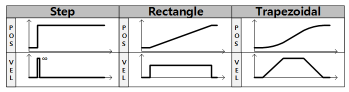
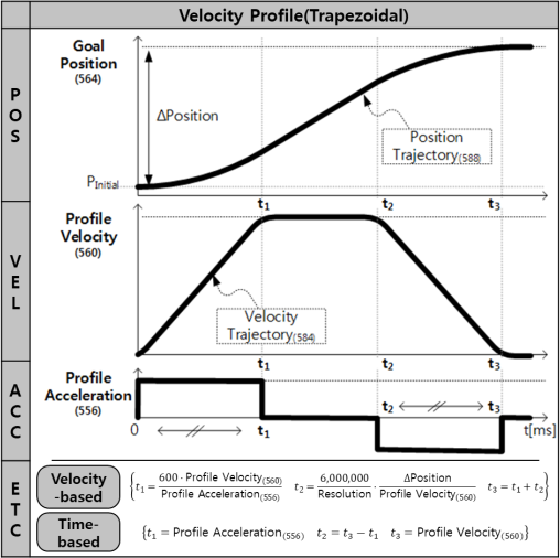
The Profile is an acceleration/deceleration control technique to reduce vibration, noise and load on the motor by controlling dramatically changing velocity and acceleration.
It is also called Velocity Profile as it controls acceleration and deceleration based on velocity.
This device provides the following 3 types of profile.
Profiles are usually selected by the combination of Profile Velocity(560) and Profile Acceleration(556).
Trapezoidal Profile is exceptionally applied with additional factor: travel distance(ΔPos, the distance between desired position and present position).
When given Goal Position(564), the device’s profile creates desired velocity trajectory based on present velocity(initial velocity of the Profile).
When the device receives updated desired position via Goal Position(564) while it is moving toward the previous desired position, velocity will smoothly changed for the new desired velocity trajectory.
Maintaining velocity continuity while updating the desired velocity trajectory is called “Velocity Override”.
For easier calculation in this example, let’s assume that the initial velocity of the Profile is 0.
The following explains how Profile processes Goal Position(564).
- An Instruction is recieved via communication bus, then registered in Goal Position(564).
- Accelerating time(t1) is calculated from Profile Velocity(560) and Profile Acceleration(556).
- Profile type is decided based on Profile Velocity(560), Profile Acceleration(556) and total travel distance(ΔPos, the distance difference between desired position and present position).
- Selected Profile type is stored at Moving Status(571).(Refer to the Moving Status(571))
- The device is driven by the calculated desired trajectory from Profile.
- The desired velocity trajectory and the desired position trajectory calculated by the Profile are saved at Velocity Trajectory(584) and Position Trajectory(588) respectively.
| Condition | Types of Profile |
|---|---|
| Profile Velocity(560) = 0 | Profile not used (Step Instruction) |
| (Profile Velocity(560) ≠ 0) & (Profile Acceleration(556) = 0) | Rectangular Profile |
| (Profile Velocity(560) ≠ 0) & (Profile Acceleration(556) ≠ 0) | Trapezoidal Profile |
NOTE : Step and Trapezoidal Profiles are only supported while Velocity Override is supported as well.
Acceleration time(t1) can be calculated as below equation.
t1 = 600 * {Goal Velocity(552) / Profile Acceleration(556)}
Goal Position(564)
Desired position can be set with Goal Position(564).
This value must be in between Min Position Limit(52) and Max Position Limit(48).
| Model Name | Goal Position = 0 | Goal Position = 740 |
|---|---|---|
| RH-P12-RN | 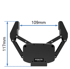 |
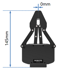 |
Realtime Tick(568)
This value indicates device’s internal time.
| Unit | Value Range | Description |
|---|---|---|
| 1 [msec] | 0 ~ 32,767 | The value resets to ‘0’ when it exceeds 32,767 |
Moving(570)
This value indicates whether the device is in motion or not. If absolute value of Present Velocity(576) is greater than Moving Threshold(24), Moving(570) is set to ‘1’. Otherwise, it will be cleared to ‘0’.
However, this value will always be set to ‘1’ regardless of Present Velocity(576) while Profile is in progress with Goal Position(564) instruction.
Moving Status(571)
This value provides additional information about the movement. In-Position Bit(0x01) only works with Current-based Position Control Mode.
| Details | Description | ||
|---|---|---|---|
| Bit 7 | 0x80 | - | Unused |
| Bit 6 | 0x40 | - | Unused |
| Bit 5 ~ Bit 4 |
0x30 | Profile Type(0x30) Profile Type(0x10) Profile Type(0x00) |
Trapezoidal Velocity Profile Rectangular Velocity Profile Profile unused(Step) |
| Bit 3 | 0x08 | - | Unused |
| Bit 2 | 0x04 | - | Unused |
| Bit 1 | 0x02 | - | Unused |
| Bit 0 | 0x01 | In-Position | The device is reached to desired position |
Present PWM(572)
The Present PWM(124) indicates current PWM. For more details, please refer to the Goal PWM(548).
Present Current(574)
This value indicates the present current flowing on the motor. For more details, please refer to the Goal Current(550).
Present Velocity(576)
This value indicates the present Velocity. For more details, please refer to the Goal Velocity(552).
Present Position(580)
This value represents present position of the device.
| Model Name | Goal Position = 0 | Goal Position = 740 |
|---|---|---|
| RH-P12-RN | |
|
Velocity Trajectory(584)
This is a desired velocity trajectory created by Profile. For more details, please refer to the Profile Velocity(560).
Current-based Position Control Mode : The desired Velocity Trajectory is used to create Position Trajectory(588). When Profile reaches to an endpoint, Velocity Trajectory(584) is set to ‘0’.
Position Trajectory(588)
This is a desired position trajectory created by Profile. This value is only used in Current-based Position Control Mode. For more details, please refer to the Profile Velocity(560).
Present Input Voltage(592)
This value indicates present voltage that is being supplied to the device. For more details, please refer to the Max/Min Voltage Limit(32, 34).
Present Temperature(594)
This value indicates internal temperature of the device. For more details, please refer to the Temperature Limit(31).
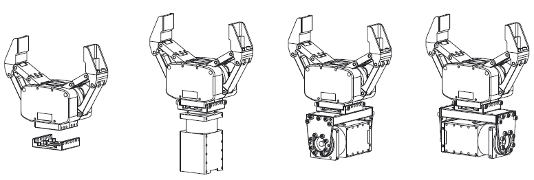
How to Assemble
Option Frame Assembly
Reference
Connector Information
| Item | RS-485 | External Port |
|---|---|---|
| Pinout | 1 GND2 VDD3 DATA+4 DATA- |
1 GND2 VDD3 PORT 14 PORT 25 PORT 36 PORT 4 |
| Diagram |  |
 |
| Housing | JST EHR-04 |  MOLEX 51021-0600 |
| PCB Header |  JST B4B-EH-A |
 MOLEX 53047-0610 |
| Crimp Terminal | JST SEH-001T-P0.6 | MOLEX 50079-8100 |
| Wire Gauge for DYNAMIXEL | 21 AWG | 21 AWG |
Drawings
Download RH-P12-RN(PDF).zip
Download RH-P12-RN(STP).zip
Certifications
Please inquire us for information regarding unlisted certifications.
FCC
Note: This equipment has been tested and found to comply with the limits for a Class B digital device, pursuant to part 15 of the FCC Rules. These limits are designed to provide reasonable protection against harmful interference in a residential installation. This equipment generates, uses and can radiate radio frequency energy and, if not installed and used in accordance with the instructions, may cause harmful interference to radio communications. However, there is no guarantee that interference will not occur in a particular installation. If this equipment does cause harmful interference to radio or television reception, which can be determined by turning the equipment off and on, the user is encouraged to try to correct the interference by one more of the following measures:
- Reorient or relocate the receiving antenna.
- Increase the separation between the equipment and receiver.
- Connect the equipment into an outlet on a circuit different from that to which the receiver is connected.
- Consult the dealer or an experienced radio/TV technician for help.
WARNING
Any changes or modifications not expressly approved by the manufacturer could void the user’s authority to operate
the equipment.