
RB-88 Controller
Introduction
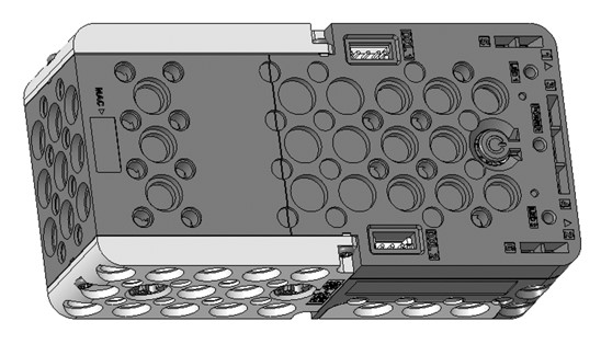
- The RB-88 is a controller used in the OLLO Spark and OLLO Excel Kit, featuring Bluetooth functionality and built-in devices such as motor output shafts and various input/output devices (infrared sensor, microphone, LED, buzzer).
- The RB-88 controller is compatible with ROBOTIS’ 12mm standard products.
- Firmware updates and recovery can be done via the STEAMCUP app.
- You can program the RB-88 with R-Block and download the program to make the controller operate.
Specifications
| Item | Specification |
|---|---|
| Weight | 160g |
| Controller | Arm® Cortex®-M4 MCU |
| Dimensions | 120 mm x 60 mm x 36 mm |
| Motor Output Shafts | Central Shaft x 2, Rear Shaft x 2 |
| Gear Ratio | Central Shaft 30:1, Rear Shaft 60:1 |
| Speed | Central Shaft 135 RPM, Rear Shaft 270 RPM (at 4.5V) |
| Operating Voltage | 3.6V ~ 4.8V (AA batteries x 3) |
| Internal I/O Devices | Infrared Sensor (Obstacle Detection) x 6, Microphone (Sound Detection) x 1, Buzzer x 1, AUX LED x 2 (Orange, Green), POWER LED x 1 (Blue) |
| External I/O Ports | DXL TTL 3P Port x 2 |
![]()
DANGER
(Ignoring these warnings may cause serious injury or death)
- Never place items containing water, flammables/open flames, or solvents near the product.
- Never place fingers, arms, toes, and other body parts near product during operation.
- Cease operation and remove power from the product if the product begins to emit strange odors, noises, or smoke.
- Keep product out of reach of children.
- Check input polarity before installing or energizing wiring or cables.
![]()
CAUTION
(Ignoring these warnings may cause mild injury or damage to the product)
- Always comply with the product’s offical operating environment specifications including input voltage, current, and operating temperature.
- Do not insert blades or other sharp objects during product operation.
![]()
ATTENTION
(Ignoring these warnings may cause minor injury or damage to the product)
- Do not disassemble or modify the product.
- Do not drop the product or apply strong impacts.
- Do not connect or disconnect DYNAMIXEL cables while power is being supplied.
Control Table
Control Table consists of data regarding the current status and operation of controller. The user can control controller by changing data of Control Table via Instruction packet.
-
EEPROM and RAM
Data in RAM area is reset to initial values whenever the power is turned on while data in EEPROM area is kept once values are set even if the power is turned off. -
Address
Represents the location of data. To read from or write data to the control table the user should assign the correct address in the Instruction packet. -
Access
Controller has two kinds of data: Read-only data, used mainly for sensing, and read-and-write data used for driving. -
Initial Value
In case of data in the EEPROM Area, the initial values on the right side of the below Control Table are the factory default settings.
In case of data in the RAM Area, the initial values on the right side of the following control table are the ones when the power is turned on. -
Size
The Size of data varies from 1 ~ 4 bytes depend on their usage. Please check the size of data when updating the data with an Instruction Packet.
RB-88 Control Table
| Area | Address | Size[Byte] | Name | Access | Initial Value | Range | Unit | Setting Value | Description |
|---|---|---|---|---|---|---|---|---|---|
| EEPROM | 0 | 2 | Model Number | R | 491 | - | - | - | Model number |
| EEPROM | 6 | 1 | Firmware Version | R | - | - | - | - | Firmware version |
| EEPROM | 7 | 1 | ID | R | 200 | - | - | - | Controller ID |
| EEPROM | 8 | 1 | Baud Rate | RW | 3 | 0 ~ 3 | - | 0: 9600 bps 1: 57600 bps 2: 115200 bps 3: 1 Mbps |
Communication speed via Dynamixel |
| EEPROM | 11 | 1 | Bootloader Version | R | - | - | - | - | Bootloader version |
| RAM | 21 | 1 | Mode Number | RW | - | 1 ~ 6 | - | 1: Play Mode 2: Manage Mode 3: Reboot 4: TTL Bootloader 5: BLE Bootloader 6: Power Off |
Mode number 1: Play Mode: Run the stored Blockly program mode 2: Manage Mode: External control waiting mode 3: Reboot: Reboot 4: TTL Bootloader: Bootloader using 3-pin TTL port 5: BLE Bootloader: Bootloader using BLE 6: Power Off: Turn off power |
| RAM | 25 | 1 | Press Count | R | - | - | - | - | Number of times the power button was pressed when turning on the controller |
| RAM | 49 | 1 | BLE Paired | R | 0 | 0 ~ 1 | - | 0: False 1: True |
Current BLE pairing status |
| RAM | 51 | 4 | Serial Screen | W | 0 | -32768 ~ 32767 | - | - | 4-byte signed value for screen output (no line feed) |
| RAM | 55 | 4 | Serial Screen LF | W | 0 | -32768 ~ 32767 | - | - | 4-byte signed value for screen output (with line feed) |
| RAM | 59 | 2 | TX Remote Control Data | W | - | - | - | - | Remote control data to be sent via BLE |
| RAM | 61 | 2 | RX Remote Control Data | R | - | - | - | - | Remote control data received via BLE |
| RAM | 63 | 1 | RX Remote Control Data Arrived | R | 0 | - | - | 0: False 1: True |
Whether remote control data received via BLE is available |
| RAM | 66 | 2 | Motion Index Number | RW | 0 | 0 ~ 65535 | - | 0: Stop motion using motion stop unit 1~65532: Execute motion of selected unit 65533: Stop motion immediately 65534: Stop motion at current key-frame 65535: Stop motion at current unit |
Play a specific motion or stop the currently playing motion. |
| RAM | 68 | 1 | Motion Play Status | R | 0 | 0 ~ 1 | - | 0: False 1: True |
Check if motion is being executed. |
| RAM | 71 | 2 | Delay Millisecond | W | 0 | 0 ~ 60000 | ms | - | Delay for the specified time (available only during Blockly execution). |
| RAM | 76 | 1 | Power Save Timer | RW | 5 | 0 ~ 255 | minute | 0: Never turn off 1 ~ 255: Turn off after m minutes if no 2.0 packets are received |
Set auto power-off timer |
| RAM | 79 | 1 | Red LED | RW | 0 | 0 ~ 1 | - | 0: OFF 1: ON |
Turn on/off red LED |
| RAM | 80 | 1 | Green LED | RW | 0 | 0 ~ 1 | - | 0: OFF 1: ON |
Turn on/off green LED |
| RAM | 84 | 1 | Buzzer Index | RW | 0 | 0 ~ 51 | - | - | - Melody mode: Execute melodies 0 ~ 25 when Buzzer Time(85) is 255. - Scale mode: Execute scales 0 ~ 51 when Buzzer Time(85) is 0 ~ 254. |
| RAM | 85 | 1 | Buzzer Time | RW | 0 | 0 ~ 255 | 0.1 sec | - | Enter scale mode or melody mode. Scales and melodies are played based on Buzzer Index. - 0: Play scale for 0.3 s - 1 ~ 50: Play scale for 0.1 ~ 5.0 s. Unit: 0.1 s - 50 ~ 254: Play scale for 5 s - 255: Enter melody mode |
| RAM | 86 | 1 | Sound Detected Count | RW | 0 | 0 ~ 255 | - | - | Write: Any value initializes to 0. Read: Final detection count recognized by the built-in microphone of the controller Value change method: Maintain the value during sound detection and change to the last real-time value when the sound ends. |
| RAM | 87 | 1 | Sound Detecting Count | R | 0 | 0 ~ 255 | - | - | Read: Real-time detection count recognized by the built-in microphone of the controller Value change method: Increase during sound detection and become 0 when the sound ends. |
| RAM | 88 | 1 | Low Battery Sound Enable | RW | 1 | 0 ~ 1 | - | 0: OFF 1: ON |
Enable or disable low battery alarm. - Alarm occurs every 3 minutes when battery voltage is below 3.3V |
| RAM | 90 | 2 | Motion Count | R | - | 0 ~ 65535 | - | - | Number of motions stored in the controller |
| RAM | 92 | 2 | Motion Next Page | RW | 0 | 0 ~ 65535 | - | 0~65534: Page to move 65535: Not used |
Used to smoothly move between motion pages without stopping the motor. When creating motion profiles, the operation of the next motion page can be predicted to create smooth motion. |
| RAM | 96 | 2 | Random Min | RW | -100 | -1000 ~ 1000 | - | - | Minimum value of random number |
| RAM | 98 | 2 | Random Max | RW | 100 | -1000 ~ 1000 | - | - | Maximum value of random number |
| RAM | 100 | 2 | Random Number | R | - | -1000 ~ 1000 | - | - | Random number within the range of Random Min(96) to Random Max(98) |
| RAM | 300 | 2 | Decrease Timer | RW | 0 | -32768 ~ 32767 | ms | - | Countdown timer Decreases from the moment a value is written |
| RAM | 302 | 4 | Increase Timer | RW | 0 | 0 ~ 4294967295 | ms | - | Count-up timer Resets to 0 when any value is written |
| RAM | 360 | 2 | IR Sensor 1 | R | 0 | 0 ~ 400 | - | - | Value of IR sensor 1 |
| RAM | 362 | 2 | IR Sensor 2 | R | 0 | 0 ~ 400 | - | - | Value of IR sensor 2 |
| RAM | 364 | 2 | IR Sensor 3 | R | 0 | 0 ~ 400 | - | - | Value of IR sensor 3 |
| RAM | 366 | 2 | IR Sensor 4 | R | 0 | 0 ~ 400 | - | - | Value of IR sensor 4 |
| RAM | 368 | 2 | IR Sensor 5 | R | 0 | 0 ~ 400 | - | - | Value of IR sensor 5 |
| RAM | 370 | 2 | IR Sensor 6 | R | 0 | 0 ~ 400 | - | - | Value of IR sensor 6 |
| RAM | 440 | 12 | BLE Mac Address | R | - | - | - | - | BLE MAC address of the controller |
| RAM | 500 | 4 | Micros | R | 0 | 0 ~ 4294967295 | us | - | Time elapsed in microseconds since firmware execution |
| RAM | 504 | 4 | Millis | R | 0 | 0 ~ 4294967295 | ms | - | Time elapsed in milliseconds since firmware execution |
| RAM | 900 | 1 | Motor Stop | RW | 0 | - | - | - | Write: - 0 ~ 255: Stop all deceleration motors Read: - 0: Both motors rotating - 1: Left motor stopped, right motor rotating - 2: Left motor rotating, right motor stopped - 3: Both motors stopped |
| RAM | 901 | 1 | Motor Type | R | - | - | - | 0 : RB86 1 : RB88 |
Controller Type |
| RAM | 908 | 2 | Left Center Motor Speed | RW | - | -999 ~ 999 | - | - | Left center motor rotation speedSpeed synchronization mode- PWM value with forward and reverse corrections applied for left motor rotation Slot synchronization mode- Automatically switches to speed synchronization mode and operates in speed synchronization mode |
| RAM | 914 | 2 | Right Center Motor Speed | RW | - | -999 ~ 999 | - | - | Right center motor rotation speedSpeed synchronization mode- PWM value with forward and reverse corrections applied for right motor rotation Slot synchronization mode- Automatically switches to speed synchronization mode and operates in speed synchronization mode |
| RAM | 916 | 2 | Center Motor Forward Speed | W | 0 | 0 ~ 999 | - | - | Center motor forward speedSpeed synchronization mode- Update the forward correction value until the speed of the left and right motors is the same every 360 degrees rotation of the center wheel and adjust the PWM value - Forward correction value is stored in EEPROM and maintained even if the power is turned off Slot synchronization mode- Synchronize the positions of the left and right wheels by checking the position where the center wheel rotates 180 degrees using the slot on the motor |
| RAM | 918 | 2 | Center Motor Backward Speed | W | 0 | 0 ~ 999 | - | - | Center motor backward speedSpeed synchronization mode- Update the reverse correction value until the speed of the left and right motors is the same every 360 degrees rotation of the center wheel and adjust the PWM value - Reverse correction value is stored in EEPROM and maintained even if the power is turned off Slot synchronization mode- Synchronize the positions of the left and right wheels by checking the position where the center wheel rotates 180 degrees using the slot on the motor |
| RAM | 920 | 2 | Center Motor Turn Left Speed | W | 0 | 0 ~ 999 | - | - | Center motor turn left speedSpeed synchronization mode- Left motor rotates with PWM value applied with reverse correction, and right motor rotates with PWM value applied with forward correction Slot synchronization mode- Synchronize the positions of the left and right wheels by checking the position where the center wheel rotates 360 degrees using the slot on the motor |
| RAM | 922 | 2 | Center Motor Turn Right Speed | W | 0 | 0 ~ 999 | - | - | Center motor turn right speedSpeed synchronization mode- Left motor rotates with PWM value applied with forward correction, and right motor rotates with PWM value applied with reverse correction Slot synchronization mode- Synchronize the positions of the left and right wheels by checking the position where the center wheel rotates 360 degrees using the slot on the motor |
| RAM | 943 | 1 | Sync Mode | RW | 0 | 0 ~ 1 | - | 0 : OFF 1 : ON |
Synchronization mode setting0: Speed synchronization mode- Measure the speed at which the center motor reference wheel rotates 360 degrees to synchronize the speed of the left and right motors 1: Slot synchronization mode- When slot synchronization mode is set, the motor moves to the zero position - Detect the position where the center motor reference wheel rotates 180 degrees when the motor rotates, and synchronize the position of the left and right wheels |
| RAM | 945 | 1 | Sync State | R | 0 | 0 ~ 1 | - | 0 : False 1 : True |
Check synchronization process status |
| RAM | 950 | 2 | Left Back Motor Speed | RW | 0 | -999 ~ 999 | - | - | Left back motor rotation speedSpeed synchronization mode- PWM value with forward and reverse corrections applied for left motor rotation Slot synchronization mode- Automatically switches to speed synchronization mode and operates in speed synchronization mode |
| RAM | 952 | 2 | Right Back Motor Speed | RW | 0 | -999 ~ 999 | - | - | Right back motor rotation speedSpeed synchronization mode- PWM value with forward and reverse corrections applied for right motor rotation Slot synchronization mode- Automatically switches to speed synchronization mode and operates in speed synchronization mode |
| RAM | 954 | 2 | Back Motor Forward Speed | W | 0 | 0 ~ 999 | - | - | Back motor forward speedSpeed synchronization mode- Update the forward correction value until the speed of the left and right motors is the same every 180 degrees rotation of the back wheel and adjust the PWM value - Forward correction value is stored in EEPROM and maintained even if the power is turned off Slot synchronization mode- Automatically switches to speed synchronization mode and operates in speed synchronization mode |
| RAM | 956 | 2 | Back Motor Backward Speed | W | 0 | 0 ~ 999 | - | - | Back motor backward speedSpeed synchronization mode- Update the reverse correction value until the speed of the left and right motors is the same every 180 degrees rotation of the back wheel and adjust the PWM value - Reverse correction value is stored in EEPROM and maintained even if the power is turned off Slot synchronization mode- Automatically switches to speed synchronization mode and operates in speed synchronization mode |
| RAM | 958 | 2 | Back Motor Turn Left Speed | W | 0 | 0 ~ 999 | - | - | Back motor turn left speedSpeed synchronization mode- Left motor rotates with PWM value applied with reverse correction, and right motor rotates with PWM value applied with forward correction Slot synchronization mode- Automatically switches to speed synchronization mode and operates in speed synchronization mode |
| RAM | 960 | 2 | Back Motor Turn Right Speed | W | 0 | 0 ~ 999 | - | - | Back motor turn right speedSpeed synchronization mode- Left motor rotates with PWM value applied with forward correction, and right motor rotates with PWM value applied with reverse correction Slot synchronization mode- Automatically switches to speed synchronization mode and operates in speed synchronization mode |
| RAM | 1101 | 1 | DXL Count | R | 0 | - | - | - | Number of Dynamixels connected to the controller |
| RAM | 1102 | 8 | DXL ID | R | - | - | - | - | Bits corresponding to Dynamixel IDs connected to the controller are set to 1. Data is displayed in Littlen endian format. Example: - ID 1 and 3 Dynamixels connected - Binary: 00000000 00000000 00000000 00000000 00000000 00000000 00000000 00001010 - Hexadecimal: 00 00 00 00 00 00 00 0A - ID 2 and 8 Dynamixels connected - Binary: 00000000 00000000 00000000 00000000 00000000 00000000 00000001 00000100 - Hexadecimal: 00 00 00 00 00 00 01 04 |
| RAM | 1166 | 1 | DXL Scan | W | - | 0 ~ 1 | - | - | Dynamixel scan on the controller |
| RAM | 1167 | 1 | DXL Reboot | W | - | 0 ~ 252 | - | - | Reboot the Dynamixel with the selected ID |
| RAM | 1322 | 1 | DXL Torque | W | - | - | - | - | Turn on or off torque for all connected Dynamixels |
| RAM | 1500 | 2 | Line Tracer Speed | RW | 0 | - | - | 0 : End line tracing 1 ~ 999 : Line tracing speed |
Set line tracing speed |
| RAM | 1505 | 1 | Line Category | R | 0 | - | - | 0 : On line 1 : Off line 5 : + Intersection 6 : T Intersection 7 : ⊣ - Left Turn 8 : ⊢ - Right Turn 9 : ⏋Left Corner 10 : ⎾ Right Corner 11 : | Dead End 12 : Blank 1 [—- —–] 13 : Blank 2 [– — –] |
Detected line category |
Layout
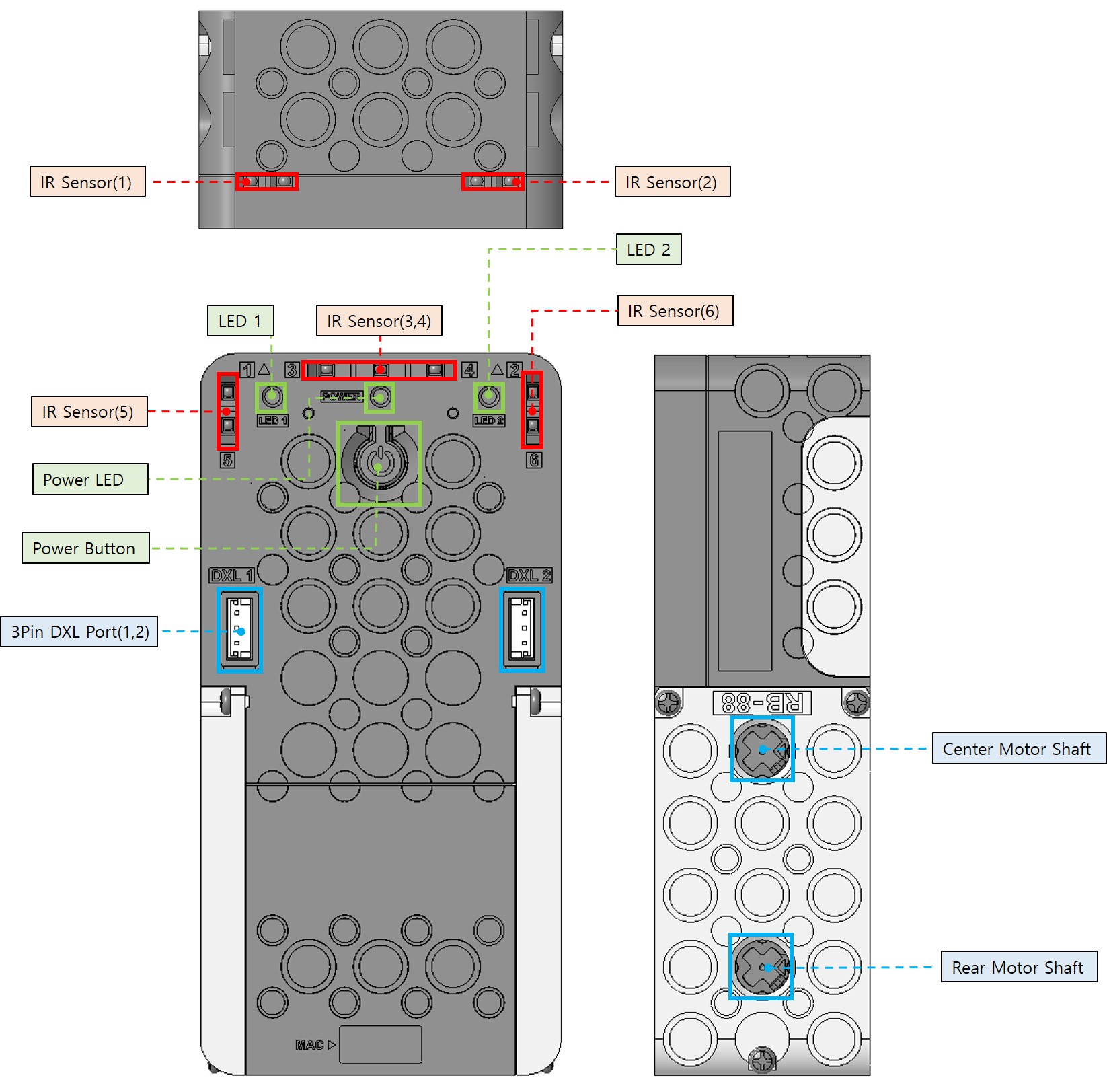
- Power Button: Short press to turn on. The power LED lights up, and the controller enters Play Mode and downloaded program on the controller starts running. If held for more than 3 seconds, the buzzer beeps twice, indicating Manage Mode. Holding for about 9 seconds results in three beeps, indicating Firmware Recovery Mode.
- Power LED: Pressing the power button causes the blue LED to flash. When connected to the BT-430 dongle, the blue LED remains on without flashing.
- LED 1,2 (LED): Indicator LEDs that can be turned on or off through programming.
- IR Sensor (1~6) (Infrared Sensor): Six infrared sensors, allowing programming using sensor values from different directions.
- 3Pin DXL Port (1,2) (3-pin port): Located below the power button, can be used to connect XL330-M077-T and XL330-M288-T, and more.
- Center Motor Shaft: For attaching a cross axle. The gear ratio is 30:1.
- Rear Motor Shaft: For attaching a cross axle. The gear ratio is 60:1.
Power Supply
The RB-88 is powered by three AA batteries.
Controller Modes
Play Mode
- With the controller off, briefly press the power button to start, and the blue LED lights up, indicating the controller is in Play mode.
- Play mode executes R-Block programs downloaded to the controller.
- The number of times you press the start button in succession at the initial start increases the button press count. You can use this parameter for programming to make RB-88 perform different actions depending on the number of times you press the start button.
- In Play mode, if Bluetooth is not paired with a leader device, the blue LED will flash. When paired, the blue LED remains on without flashing.
Manage Mode
- With the controller off, press and hold the power button for about 1 second until you hear two short beeps, and the blue LED lights up, indicating the controller is in Manage mode.
- In Manage mode, you can download R-Block programs.
- In Manage mode, if Bluetooth is not paired with a leader device, the blue LED will flash. When paired, the blue LED remains on without flashing.
Recovery Mode
- With the controller off, press and hold the power button for about 9 seconds until there is no more sound. This indicates entry into Recovery mode.
- In Recovery mode, both the orange and blue LEDs will flash.
- Connect the RB-88 controller in Recovery mode by clicking “Add Robot” in the STEAMCUP app. (Connect from Mobile)
- Do not close the app during the update.
- Place your smartphone as close as possible to the controller during the update.
Controller Shutdown
To turn off the controller when it’s on, press the start button again.
Control Dynamixels via Bluetooth
- When the controller is in Manage mode, you can control Dynamixels using their IDs connected to the controller.
- After confirming the model name of the Dynamixels connected to the controller, please refer to the Dynamixel control table in the e-Manual.
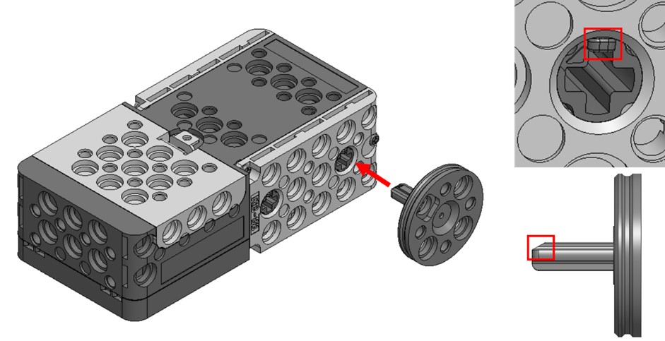
Cross Hub Assembly
Insert the end of the cross shaft into the cross hub on the RB-86, making sure their directions match.
Connect to STEAMCUP
Connect from PC
-
Navigate to the STEAMCUP website.
- Search for
STEAMCUPon Google or visit the STEAMCUP website.

- Search for
-
Click on the hamburger menu in the upper right corner, sign up, and log in.

-
Click on
Add Robot.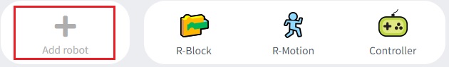
-
Select the controller you want to connect to from the Bluetooth device selection window and proceed with pairing.
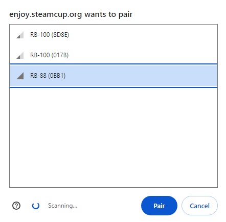
-
The RB-88 will beep once, indicating a successful connection.
Connect from Mobile
-
Download the STEAMCUP app from the Google Play Store or App Store.

-
Run the STEAMCUP app, sign up, and log in.
-
Click on
Add Robotand select the controller you want to connect to.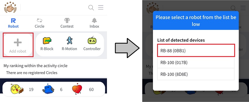
-
The RB-88 will beep once, indicating a successful connection.
Firmware Update
-
Connect to your RB-88 via the STEAMCUP app.
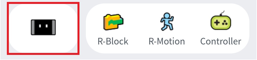
-
Click on the RB-88 icon.
-
Click on the Firmware Recovery/Update button.
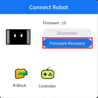
-
Follow the wireless firmware update instructions.
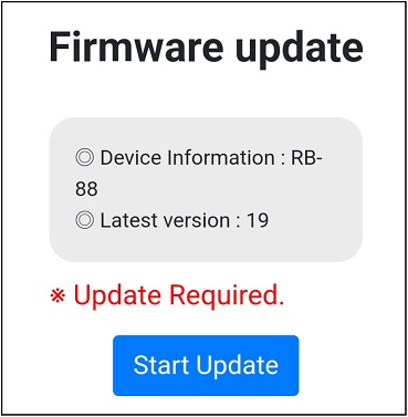
Note: PC STEAMCUP does not support firmware update functionality.
Connect to Remote Controller
Connect to RC-100B or RC-300
- Turn on the RB-88 without an active BLE connection.
- Power on the RC-100B (equipped with BT-410 MASTER module) or RC-300 near the RB-88 controller.
- The RC-100B (BT-410 MASTER module equipped) or RC-300 will automatically connect to the nearby RB-88 controller.
Connect from STEAMCUP to Remote Controller
-
Connect RB-88 from your PC or the STEAMCUP app.
-
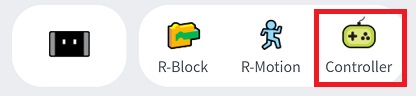
Select the remote controller icon to open the virtual remote controller.
Straightness Calibration
-
When running either of the following R-Block blocks, the RB-86 will automatically attempt to correct straightness during motion.


- Long-distance travel is required for straightness calibration to be completed.
- The straightness calibration value is retained even when the power is turned off.