
Introduction
Robots of 4 DOF can be built with Beginner Kit. This kit is recommended for people who meet robots for the first time.
- Learning the principle of robot building
- You can build up 14 example robots with Bioloid Beginner Kit and learn the principle of robot building.
- From a simple barrier bar of 1 DOF to an automobile or walking droid of 4 DOF, it is possible to build the robot and edit the example programs. It will help increasing your understanding for robot programming.
- Purchasing 4 more AX-12+ for Bioloid Beginner Kit, you can build intermediate-level robots of 8 DOF.
- Also, purchasing 14 additional AX-12+ for Bioloid Beginner Kit and frame set for Comprehensive Kit, you can build intermediate-level robots and advanced-level robots of 18 DOF.
- You can also create your one and only robot by designing, assembling and programming it by yourself.
WARNING : ROBOTIS BIOLOID Beginner has been discontinued.
Getting Started
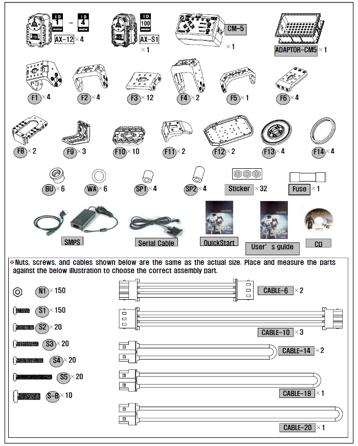
Part List
Preparation
As shown in BIOLOID learning material, CM-5 is supposed to support existing BIOLOID software (Behavior Control Program, Motion Editor etc). Therefore, if you want to use RoboPlus software in CM-5, you need to change the firmware into other firmware which supports Roboplus. However, if you change the firmware, you would no longer be able to use the existing Bioloid software.
The new-upgraded RoboPlus is an integrated programming software which can control Robotis products. Therefore, CM-5 based robots can be controlled by programming with RoboPlus. The usage is as below.
- Download the Latest Version of RoboPlus.
- Execute RoboPlus after installation.
- Select RoboPlus Manager.
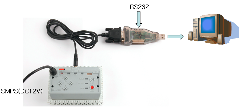
- Connect CM-5 with the PC using serial cable.
-
Execute Firmware Wizard by pressing
Control Restorationicon on RoboPlus Manager.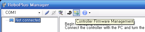
-
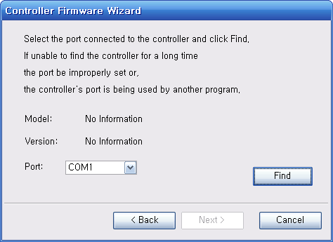
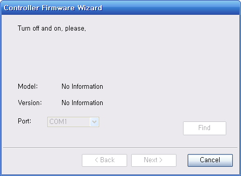
Select the port connected to the controller. Users must set manually the port connected to the controller. Finish other programs and continue the process since the controller cannot be recognized in case the port is in use. Select the port connected to the controller and press “Find” button.
-
Turn the power of the controller off and on. To find the controller, the controller to be restored must be turned off and on.
-
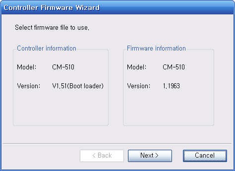
Check the controller information. When the controller is found, the information of current controller and the firmware to download are appeared. Check the model name whether the controller is connected by the user or not. (The version of controller information is for Boot Loader, not for firmware.)
-
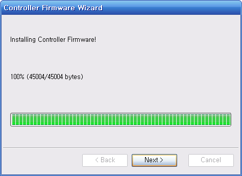
Start the firmware installation again. Press “Next” button to start firmware restoration. Please be careful not to interrupt the connection or turn the power off until it is completed.
-
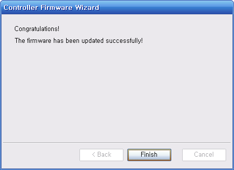
Check the controller firmware re-installation result.
Executing above procedure, CM-5 can be programmed with RoboPlus. Try to make the best robot with upgraded RoboPlus.
Operating
Before executing the program, the appropriate task codes and motions must be downloaded into the robot.
-
Turn on the power. If it is not charged,
POWERLED does not blink. Please refer to Charging.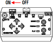
-
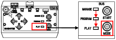
Make the LED on Play blink by pressing MODE button.
-
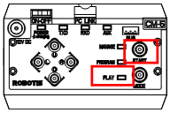
Press START button to execute the program. The LED is not blinking while the program is being executed.
Charging CM-5
To move a robot when it is not connected with SMPS, you have to use a battery. If the battery is discharged, please use by charging it according to following procedures.
-
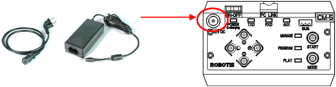
Connect SMSPS to CM-5.
-
Turn on the CM-5 Power and press the
Ubutton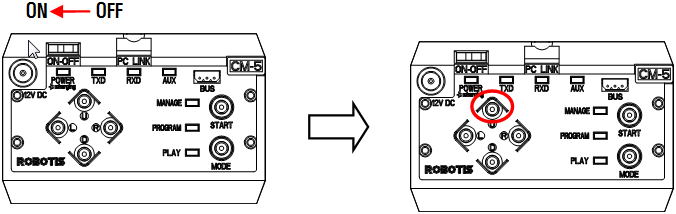
NOTE : While the CM-5 is being charged, the power LED blinks. The speed of blinking shows how much it is left before finishing the charging. It will be more faster as it completes the charging. Once the charging is done, it will blink for every 2 seconds.
Tutorial
Screen Output
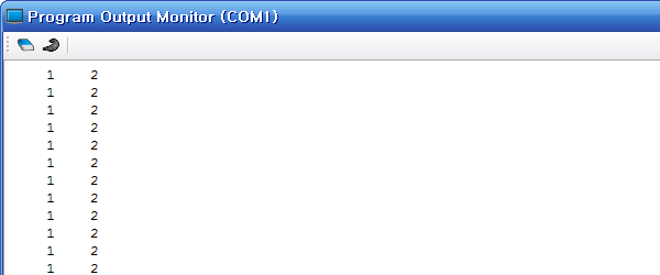
Objective for this tutorial is to print 1 and 2 on the output screen as below.
Write Task Code
-
Execute RoboPlus Task Program.
As seen in the picture below, go to
Start > All Programs > ROBOTIS > RoboPlus > Software > RoboPlus Taskto execute RoboPlus Task.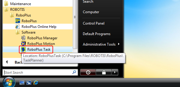
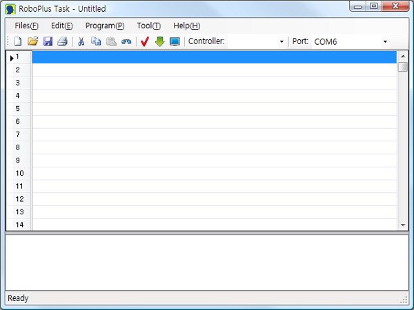
- RoboPlus Task Initial Screen
-
Select a Controller.
Double click an empty line or press
Enter, In theSelect Controlwindow, select the controller to use, then press theOKbutton.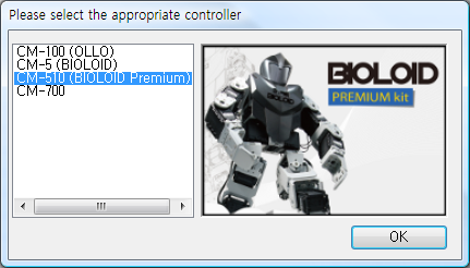
-
Generating
Start Program.Select
Start Programfrom theSelect Instruction Typewindow,Start Programwill be automatically generated in RoboPlus Task.
-
Input
Endless LoopcommandTo print the numbers on the screen endlessly, use the
Endless Loopcommand(Create a command line). Double click or pressEnteron an empty line between{and}of Start Program to invoke theSelect Instruction Typewindow. SelectLoop > Endless Loop(while(1))from the list.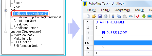
-
Input
LoadcommandUse
Loadcommand to input aPrintcommand, which is needed to print numbers on the screen. InsertExecute > Load (Assignment value)into an empty line between{and}ofEndless Loop.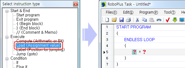
-
Load
1intoPrintChoose the left parameter ( ? ) among the
Loadparameters(Explanation on the parameter). The left parameter receives input from the right parameter. Double click the left parameter ( ? ), or pressEnterkey after clicking it once to invoke theSelect Parameter Window. SelectController > Printthen pressOK.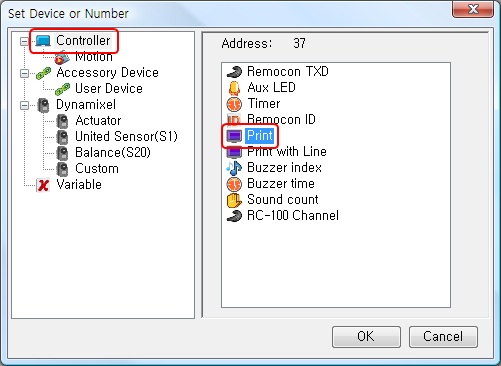
Select
Constant Numbers > Number > 1for the right parameter ( ? ) in the same way.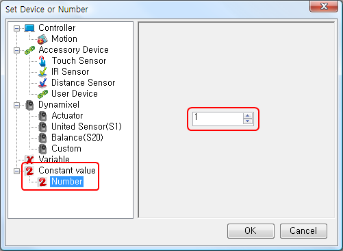
When both parameters of the
Loadcommand have been set, it should look like below.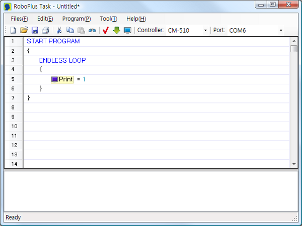
-
Load
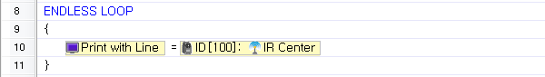
2intoPrint with LineSelect
}underPrintcommand (at the end of the endless loop section), and add new lines by pressing theSpacekey. Repeat Steps 5 and 6 to input theLoadcommand and to inputController > Print with Lineand2. The final task code is shown below.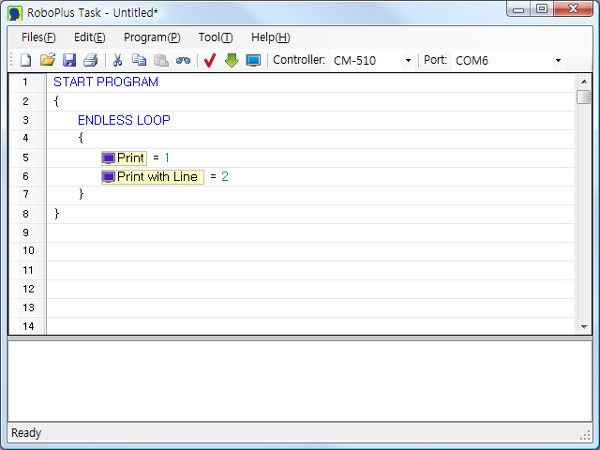
-
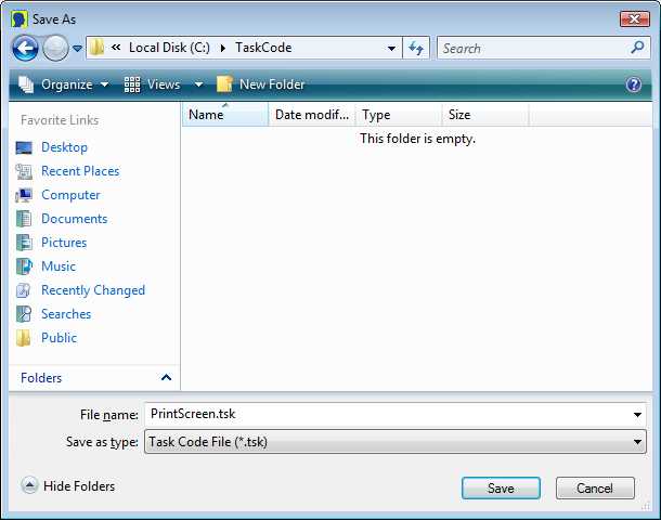
Save Task Code
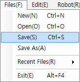
Press Ctrl + S or the Save icon.
Download Task Code
Download the task code created above.(How to Download Task Code)
Execute Task Code
-
Open the Program Output Monitor
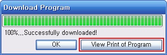
To see the output of the program, you must open the Program Output Monitor BEFORE executing the program. There are three ways to open the Program Output Monitor.
-
Click on the View Print of Program in the Download Program window
- Click on the
View Print of Programbutton in TOOLS. - Press
F5or click on View Print of Program (V) menu under Program (P).
-
-
Executing the Program
When you turn on the controller, the LED will blink, showing it is in standby mode. Press the MODE button to move it to PLAY, then press START to execute the downloaded task code. You should see “1” and “2” being printed on the Program Output Monitor.
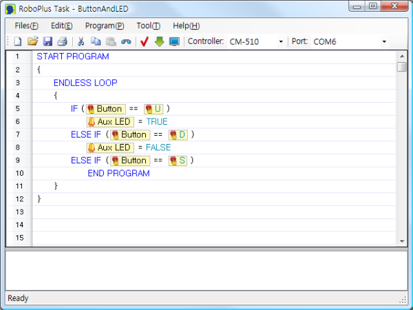
Button & LED
Objective for this tutorial is to program the U button to turn the AUX LED on and the D button to turn it off. Pressing the START button will end the program.
Write Task Code
Download Task Code
Download the task code created above.(How to Download Task Code)
Execute Task Code
Execute the program and check whether the AUX LED turns on when you press the U button and turns off when you press the D button. Press START button to end.
Attacking Duck
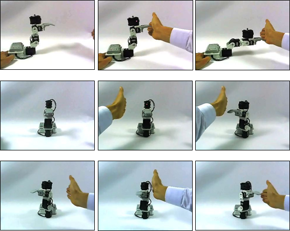
Objective for this tutorial is to build an attacking duck which attacks approaching objects. Please refer to 2-2-11 Attacking Duck of the assembly manual and complete the hardware.
CAUTION : Do not approach your face near the robot when the power is on. You may get injured by the robot.
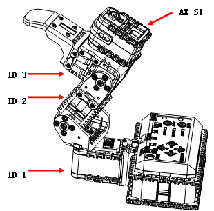
The attacking patterns of the duck are as follows.
- If any object is not detected, the robot gets ready to attack by locating ID[1] joint in the middle and folding ID[2] ~ ID[3] joints.
- If objects are detected on the left and the right side, the robot turns to the direction where objects are detected by moving ID[1] joint.
- If objects are detected at the front, the robot unfolds ID[2] ~ ID[3] joints for attack.
- It goes back to the status of “2” above.
Write Task Code
-
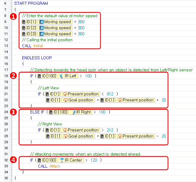
Enter the basic value of the motor’s moving speed and Call initial behavior.
-
If an object is detected from the left side of the robot, turn the beak left.
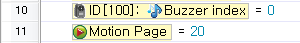
If an object is detected by the left distance sensor of AX-S1, the location value (present location value of the ID[1] joint + 20) is entered as the goal position to turn left. However, to prevent from turning too much, it is written to move only if the present location value is less than 812. -
If an object is detected from the right side of the robot, turn the beak right.
If an object is detected by the right distance sensor of AX-S1, the location value (present location value of the ID[1] joint -20) is entered as the goal position to turn right. However, to prevent from turning too much, it is written to move only if the present location value is greater than 212. -
Attack if an object is detected at the front If an object is detected by the central distance sensor of AX-S1, the robot attacks by calling “Attack with beak.”
-
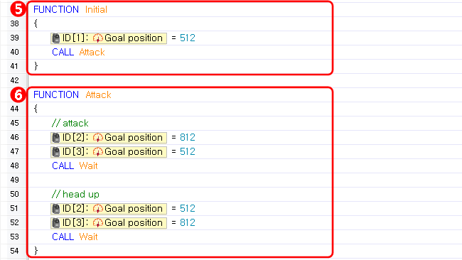
Make Initial Behavior
Move the beak in the center by inputting proper goal position value(512) into ID[1] joint, and then call “Attack with Beak” once to make initial behavior. -
Make Attack Behavior
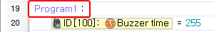
Make behaviors such as attack behaviors and raising head (ready behavior) by inputting proper goal position values into ID[2], ID[3] joints, and program “Behavior Wating(7)” function which can stop the behavior control program processing shortly until each behavior is completed.
Download Task Code
Download Complete Task Code (How to Download Task Code)
Execute Task Code
Play the downloaded task code. Check if the attacking duck attacks an approaching object or not. Do not approach your face near the robot when the power is on. You may get injured by the robot.
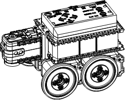
Obstacle Detecting Car
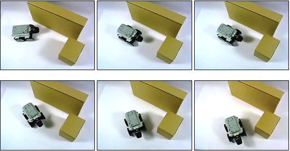
Objective for this tutorial is to build an intellectual car which runs and avoids obstacles. Please refer to 2-2-9 Obstacle Detection Car of the assembly manual and complete the hardware.
The behavior patterns of the obstacle detection car pursuant to obstacle detection in each direction are as follows.
| Left | Front | Right | Behavior Pattern |
|---|---|---|---|
| - | - | - | Forward |
| O | - | - | Turn Right |
| - | O | - | Backward |
| O | O | - | Turn Right |
| - | - | O | Turn Left |
| O | - | O | Forward |
| - | O | O | Turn Left |
| O | O | O | Stop |
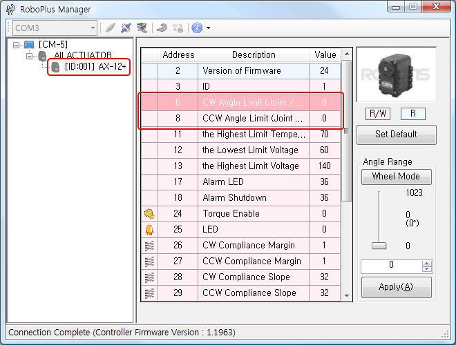
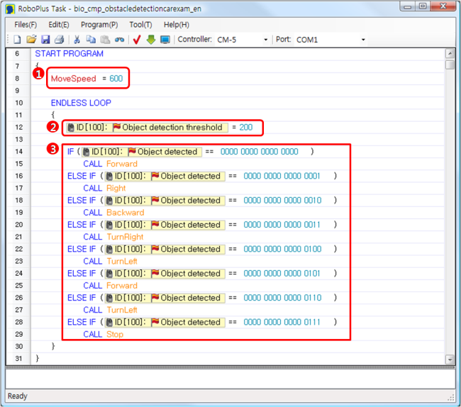
The mode of the robot is changed to wheel mode (infinite spinning mode) to use AX-12+ as the wheels of the obstacle detection car. Using RoboPlus Manager, set both the CW location limit value and the CCW location limit value of AX-12+ to 0.
Write Task Code
-
Save the basic value of the motor’s moving speed as the variable
-
Use the standard value of the object detection and the object detection existence to judge object detection. To do so, set the object detection standard value.
-
Call appropriate motion functions pursuant to the object detection existence value. (Obstacle Detection Direction)
-
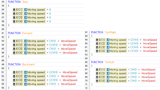
Make Stop / Forward / Backward / Turn Right / Turn Left Motions. Each motor’s moving speed is set by adding moving speed value which is the set speed value at the beginning and CW:0 and CCW:0 which represent directions.
Download Task Code
Download Complete Task Code (How to Download Task Code)
Execute Task Code
Play the downloaded task code. Check if the obstacle detection car runs and avoids the obstacles.
Walking Droid 1
Objective for this tutorial is to make a walking droid which walks forward in normal situation and avoids obstacles. Since the walking droid uses various postures when it performs such as walking, avoiding obstacles, etc., it is convenient to use by saving the postures as motions.
The following table represents the behavior patterns of the walking droid pursuant to surroundings and motion status.
| Status | Behavior |
|---|---|
| Initially executed | Stay in basic posture |
| No obstacles | Walking forward |
| Obstacles Found | Stop and walking backward |
| After walking backward | Changing direction to the left |
| Obstacles found even if turned left | Changing direction to the left |
Besides duplicated motions, 4 motions must be made as below, and the robot can avoid obstacles while walking.
- Stop
- Walking forward
- Walking backward
- Changing direction to the left
Make Motions
-
Execute RoboPlus Motion and connect to the controller. (See “Connect Robot”)
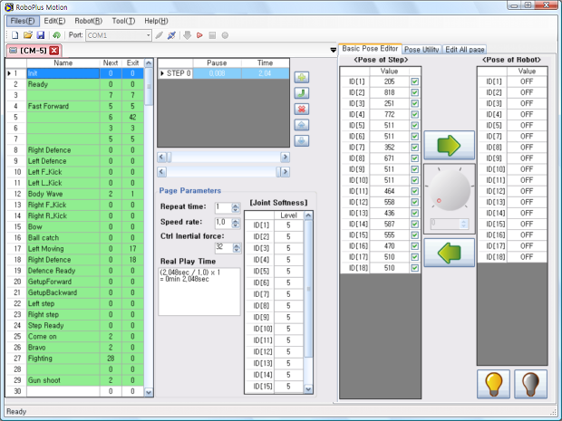
-
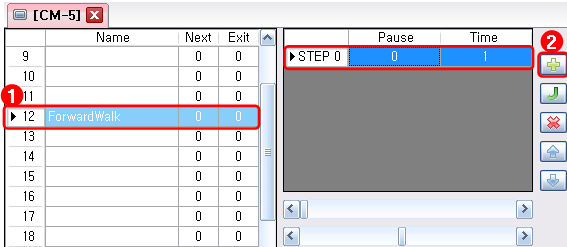
Enter the name on the page 1 to make “Stop” motion, and then add steps.
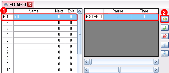
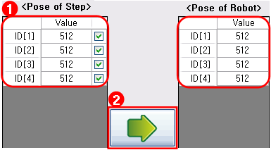
-
The joint values of ID 1, 2, 3, 4 are set to 512. The values are applied to the robot if the rightward arrow is pressed, and the set posture can be checked. (This is the method that users enter the joint values directly.)
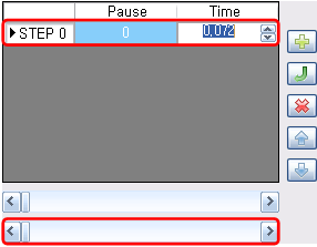
-
Adjust the executing time. It is set to 0.072 second which is the fastest time.
-
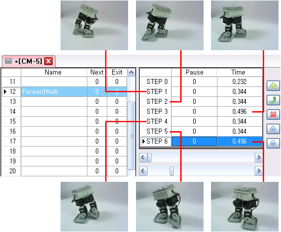
Enter the name on the page 12 to make “Walking Forward” motion, and then add steps.
-
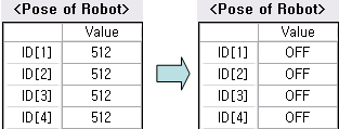
Turn off torques of all joints by pressing torque-off button. You can see all the joint values are set to “OFF.”

-
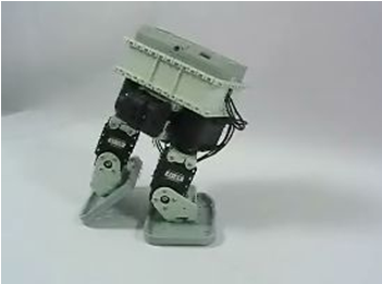
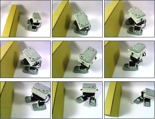
The posture of robot are set by users. The following picture shows the walking posture of the walking droid.
-
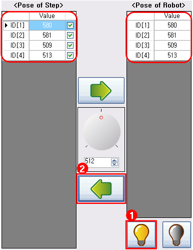
As shown above, if the posture of robot is set and the “Torque-on” button is pressed, the present joint values of the robot are entered automatically to the posture of robot. The currently entered robot’s joints can be read as steps’ posture if the leftward arrow button is pressed(This is the method that users read the joint values from the robot).
-
Repeating the procedure from number 5, add “Walking Forward” posture to each step. If the posture addition is completed, adjust the stop time and the execution time properly.
-
If the motion execution button is pressed, the steps of present page are executed sequentially. Check if the robot is operating well.

-
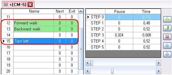
Using the same method so far, add “Walking Backward” on the page 13 and “Turn Left” on the page 15.
-
Save the works have been done so far.
Download Motion File
- Download Example Motion File (How to Download Motion File)
Walking Droid 2
Execute Motions
To use this motion after saving the motions written on RoboPlus Motion in CM-5, the motions of CM-5 must be executed in the task code. Using the two parameters, the motions of robots can be executed.
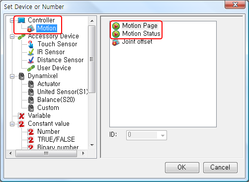
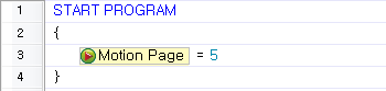
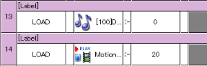
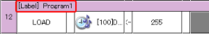
“Load” command must be used to execute the motions. If the “Load” command is selected, two parameter are created. In one parameter on the left, Motion Page in Controller -> Motion is selected, and in the other parameter on the right, the motion page number which includes desired motions is entered. If the task code is written as below and downloaded and executed in CM-5, the saved motions are executed on the page 5.
Executing Asynchronous Motions
It is a motion control method which makes robots do the next work without checking motion status of the robots. It is suitable for beginners because understanding the code is very intuitive. However, it may not be controlled as desired since duplicate execution can happen during the motion execution.
Executing Synchronous Motions
It is a motion control method which make robots do the next work after completing the execution by checking the motion status of the robots. It is suitable for intermediate-level users because the concept of Multi-Task is needed. In the case of infinite repetition motions, the task code must be written well since it may wait continuously when the motion status is checked.
Infinite Repetition Motions
It is effective to make regularly-repeated motions such as walking as an infinite repetition motion.
Write Task Code
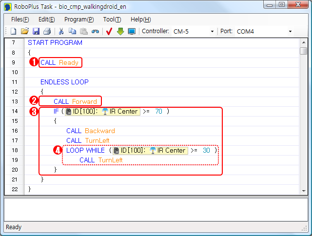
- Call “Ready” when it is executed for the first time.
- Call “Forward” if there is no obstacle.
- If an object is detected by Central Distance Sensor, Stop and walk backward,and then turn left.
-
Even though it turns left, if an object is detected by Central Distance Sensor, it turns left until no object is detected.
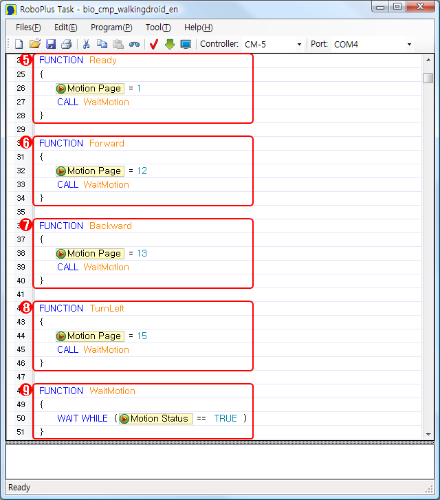
- Write a function which executes the motion on the page 1 where the “Ready” motion is saved. To wait until the motion is complete after execution, Call the function “WaitMotion.”
- Write a function which executes the motion on the page 12 where the “Forward” motion is saved. To wait until the motion is complete after execution, Call the function “WaitMotion.”
- Write a function which executes the motion on the page 13 where the “Backward” motion is saved. To wait until the motion is complete after execution, Call the function “WaitMotion.”
- Write a function which executes the motion on the page 15 where the “TurnLeft” motion is saved. To wait until the motion is complete after execution, Call the function “WaitMotion.”
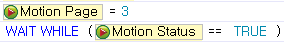
- Check the parameter value of the motion status, and write a function which waits while the motion is operating.
Download Task Code
- Download Complete Task Code (How to Download Task Code)
Execute Task Code
Play the downloaded task code. Leave obstacles on the way of the path, and then check if the walking droid avoids the obstacles and walks.
Walking Droid 3
After adding turn-right motion to previously built Walking Droid, let us try wireless control(Zigbee Communication) using RC-100. Referring to Building Walking Droid 1 - Making Motion, you can make the right-turn motion additionally on the page 4 of the motion. For Zigbee communication, CM-5 and RC-100 are equipped with ZIG-100 module. (Please refer to the explanation pages on CM-5 and RC-100.)
If U / L / D / R buttons of RC-100 are pressed, the Walking Droid performs forward / turn left / backward /turn right motions.
Write Task Code
Based on previously written task code in Building Walking Droid 2 - Task Code:
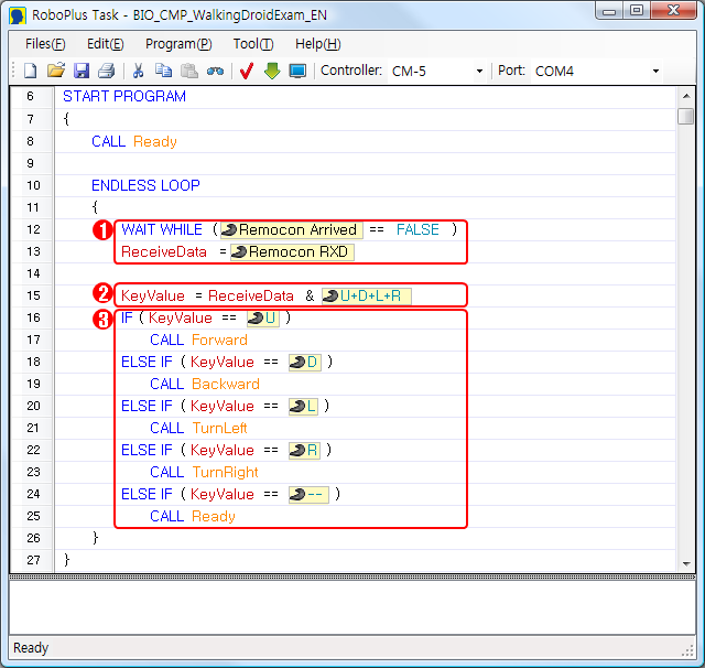
- Wait until the new wireless data is coming in, and if the data is coming in, it is saved in the received data variable.
- In the received data, only the values regarding U / D / L / R keys in RC-100 are sorted by & Bit Calculation.
- Compose the conditional sentences to perform forward / backward / turn left / turn right pursuant to the pressed buttons among all buttons. RC-Call “Ready” at the moment of releasing the pressed button of RC-100.
- Write a function which executes the motion on the page 14 where the “TurnRight” motion is saved. To wait until the motion is complete after execution, call the function “WaitMotion.”
Download Task Code
- Download Complete Task Code (How to Download Task Code)
- Download Example Motion File (How to Download Motion File)
Execute Task Code
Play the downloaded task code. Using RC-100, check if the robot moves to the desired directions by performing forward / backward / turn left / turn right motions.
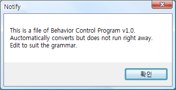
Converting .bpg to .tsk
Objective for this tutorial is to convert .bpg files written in Behavior Control Program into the Task code (.tsk) for RoboPlus Task.
Open .bpg File
-
Open .bpg file using Open Press Menu ≫ File(F) ≫ Open(O), Shortcut(Ctrl + O), or Open() to select a file.
-
Open .bpg file using Drag & Drop Drag .bpg file to RoboPlus Task.
Convert Commands
-
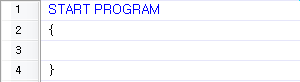
Start Program (Click here to see more information on the “Start Program.” )
It is the same as existing “Start”.
}(Section End) of Start Program is the same as existing “End”.
| RoboPlus Task | Behavior Control Program 1.0 |
|---|---|
 |
 |
-
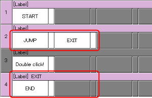
End Program ( Click here to see more information on the “End Program” )
It is the same as existing Jump to the Label of “End” Command.
| RoboPlus Task | Behavior Control Program 1.0 |
|---|---|
 |
 |
-
{(Start Block) / } (End Block) ( Click here to see more information on the “Start/End of Block.” )Lately added concept- it is not included in existing Behavior Control Program 1.0.
-
//(Comment or Memo) ( Click here to see more information. )It is the same as existing “Comment.” It does not have any influences on motions.
| RoboPlus Task | Behavior Control Program 1.0 |
|---|---|
 |
 |
-
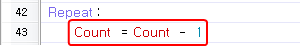
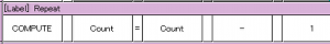
Calculate (Basic Calculation and Bit Calculation) ( Click here to see more information on the “Calculate.” )
It is the same as existing “Compute.”
| RoboPlus Task | Behavior Control Program 1.0 |
|---|---|
 |
 |
-
Load (Input Values) ( Click here to see more information on the “Load.” )
It is the same as existing “LOAD”.
| RoboPlus Task | Behavior Control Program 1.0 |
|---|---|
 |
 |
-
Label (The Site for Jump) ( Click here to see more information on the “Label.” )
It is the same as existing “Label”. However, it is not possible to be called as in Behavior Control Program 1.0; only Jump is possible.
| RoboPlus Task | Behavior Control Program 1.0 |
|---|---|
 |
 |
-
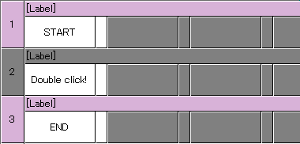
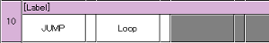
Jump (goto) ( Click here to see more information on the “Jump.” )
It is the same as existing “JUMP.”
| RoboPlus Task | Behavior Control Program 1.0 |
|---|---|
 |
 |
-
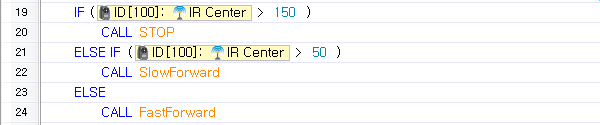
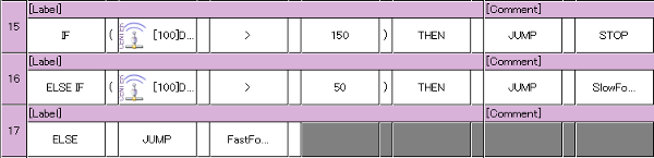
(if) / (else if) / (else) ( Click here to see more information on the “if / else if / else.” )
It is the same as existing “(IF) / (ELSE IF) / (ELSE)”.
| RoboPlus Task |
|---|
 |
| Behavior Control Program 1.0 |
|---|
 |
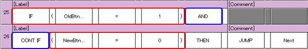
- In case that (CONT IF) comes after existing (AND), it is changed to &&.
- In case that (CONT IF) comes after existing (OR), it is changed to ||.
| RoboPlus Task |
|---|
 |
| Behavior Control Program 1.0 |
|---|
 |
-
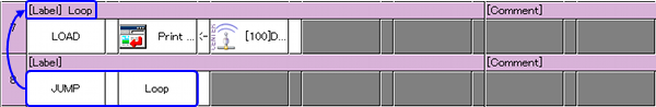
Endless Loop (while(1)) ( Click here to see more information on the “Endless Loop.” )
It is the same as the code repeating the execution of certain blocks unconditionally using Label and JUMP.
| RoboPlus Task |
|---|
 |
| Behavior Control Program 1.0 |
|---|
 |
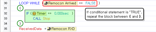
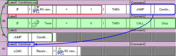
- Loop While (while(Condition)) ( Click here to see more information on the “Loop While.” ) It is the same as the code repeating the execution of certain blocks using Label and JUMP, depending on conditions.
| RoboPlus Task |
|---|
 |
| Behavior Control Program 1.0 |
|---|
 |
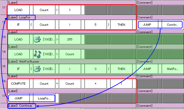
- Loop For (for) ( Click here to see more information on the “Loop For.” ) It is the same as the code repeating the execution of certain blocks only designated times using variables.
| RoboPlus Task |
|---|
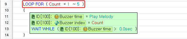 |
| Behavior Control Program 1.0 |
|---|
 |
-
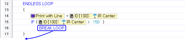
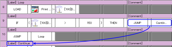
Break Loop (break) ( Click here to see more information on the “Break Loop.” )
It is used equally as the code jumping to the next label of repeated sentences.
| RoboPlus Task |
|---|
 |
| Behavior Control Program 1.0 |
|---|
 |
-
Wait While (Conditional Repeat without Execution Paragraph) ( Click here to see more information on “Wait While.” )
In case the condition is “True”, it is used equally as the code jumping to its own label.
| RoboPlus Task |
|---|
 |
| Behavior Control Program 1.0 |
|---|
 |
-
Callback Function (callback) ( Click here to see more information on “Callback” function. )
Lately added concept : it is not included in existing Behavior Control Program 1.0.
-
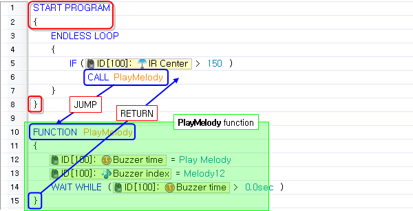
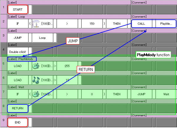
Make/Call Function ( Click here to see more information on “Make/Call Function”. )
The function is the same as the sub-routine composed of existing Label and RETURN. In RoboPlus Task, the function must be located outside of the block where is owned by Start Program (the block tied with { AND }).
| RoboPlus Task |
|---|
 |
| Behavior Control Program 1.0 |
|---|
 |
-
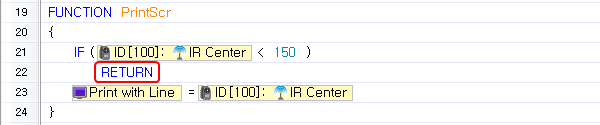
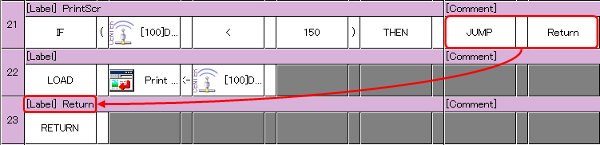
Exit Function (return) ( Click here to see more information on “Exit Function.” )
It is the same as the code performing JUMP to the label of existing RETURN.
| RoboPlus Task |
|---|
 |
| Behavior Control Program 1.0 |
|---|
 |
Video
Download
The following robots have less than 4 joints and the robots can be built with Beginner kit or Comprehensive Kit. Please refer to the assembly manual for Bioloid Beginner Kit and Comprehensive kit about how to assemble.
Download Task Code
If you want to use RoboPlus program for CM-5 (the controller used for Bioloid Beginner/Comprehensive Kits), you must update the firmware. Please refer to Firmware Update of RoboPlus Manager on how to update firmware.
Preparation
- Call the task code(*.tsk) from RoboPlus Task.
- You can open it by double-clicking the task code file.
- You can open it using Open File function of RoboPlus Task.
- You can open it by dragging & dropping on RoboPlus Task.
- Connect the PC and the Controller with USB2DYNAMIXEL.
- Turn on the power of the controller.
Download
-
Connect the controller before downloading the task code. To download the task code, the controller must be connected to the PC(Please refer to controller information for information on how to connect the controller to the PC).
-
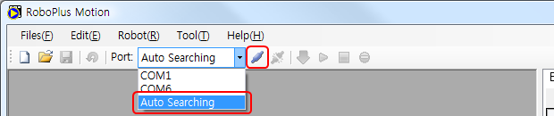
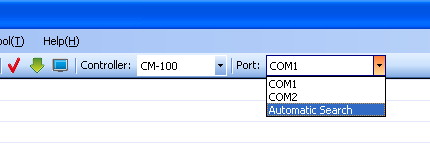
Select the correct COM port (if you know) or else use the “Automatic Search” function to easily find out the appropriate port. .
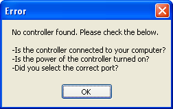
If RoboPlus Task is unable to find a controller, the following error message will be shown.
- Check if the controller is connected to the PC. (See controller information on how to connect the controller.)
- Check if the controller is turned on.
- Check if the correct communication port was chosen.
-
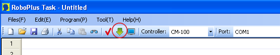
Select the download menu.
If the program has an error, you must find the error and correct it. (See “rule check error messages”)
-
Download the program.
If the downloading fails, it will automatically try again from the beginning.
-
Execute the task code and your robot will move. Turn on the controller and execute the downloaded task code(Please refer to each controller information to learn how to execute the task code).
Download Motion File
File motions can be converted into robot motions.
-
Open the file motion to download.
-
Connect to the robot.
-
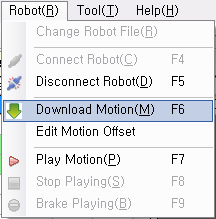
Click on the “Download Motion” menu and wait for the download to complete.
-
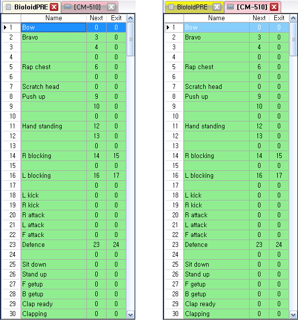
Verify that the contents of the file motion have been copied to the robot motion as seen below.
Video
Examples
Beginner Level
The following robots have joints less than 4. The robots can be built with Beginner kit or Comprehensive Kit. Please refer to the assembly manuals for Bioloid Beginner Kit and Comprehensive kit about how to assemble.
| Robot | Description |
|---|---|
1. Crossing Gate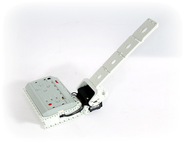 |
Download Assembly Check Task Code Download Task Code Download Video DYNAMIXEL Setting: AX-12+ ID[1]: Joint Mode- When U button on CM-5 is pressed, the gate will be opened.- When D button on CM-5 is pressed, the gate will be closed. |
2. Universal Gauge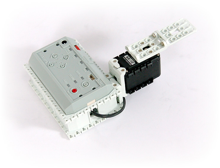 |
Download Assembly Check Task Code Download Task Code Download Video DYNAMIXEL Setting: AX-12+ ID[2]: Joint Mode- When U button on CM-5 is pressed, the speed of gauge will be increased.- When D button on CM-5 is pressed, the speed of gauge will be decreased. |
3. Sound Lever Meter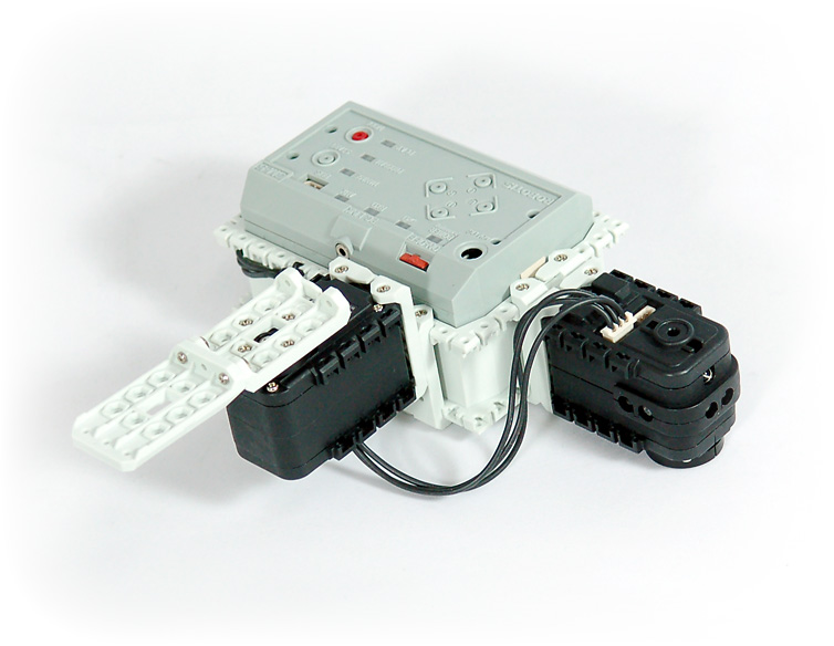 |
Download Assembly Check Task Code Download Task Code Download Video DYNAMIXEL Setting: AX-12+ ID[1]: Joint Mode, AX-S1 ID[100]- The gauge will move according to the sound volumes detected. - The sound level can be measured because the gauge makes move more when the sound is getting louder. |
4. Crocodile Mouth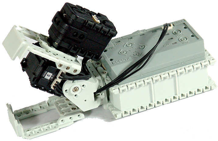 |
Download Assembly Check Task Code Download Task Code Download Video DYNAMIXEL Setting: AX-12+ ID[3]: Joint Mode, AX-S1 ID[100]- The mouth will be opened when the sensor detects an object. - The mouth will be opened, if there is an object in the mouth. - It will play a melody if no object is detected for 10 sec. |
5. Pan Tilt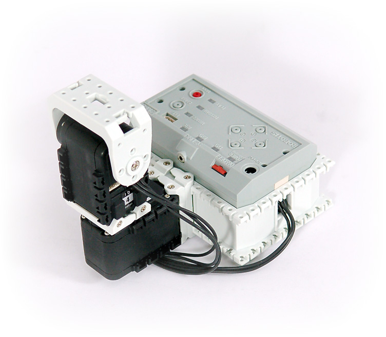 |
Download Assembly Check Task Code Download Task Code Download Video DYNAMIXEL Setting: AX-12+ ID[3, 4]: Joint Mode- Upper/lower tilt joint will move upwards, when you press the U button on CM-5. - Upper/lower tilt joint will move downwards, when you press the D button on CM-5. - Right/Left pan joint will move rightwards, when you press the R button on CM-5. - Right/Left pan joint will move leftwards, when you press the L button on CM-5. |
6. Parking Gate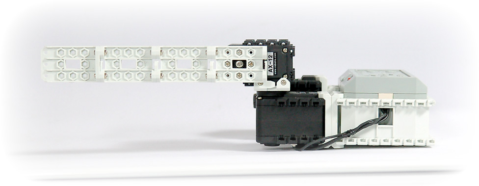 |
Download Assembly Check Task Code Download Task Code Download Video DYNAMIXEL Setting: AX-12+ ID[1, 2]: Joint Mode, AX-S1 ID[100]- If an object is detected from a sensor, the barrier bar will be open vertically. - If an object is detected from a sensor and the barrier bar is pushed ahead at the same time, the bar will be open horizontally. - The barrier bar will be closed, if no objects are detected. |
7. Melody Car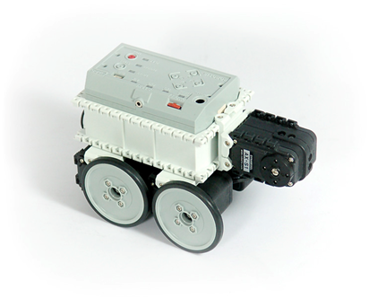 |
Download Assembly Check Task Code Download Task Code Download Video DYNAMIXEL Setting: AX-12+ ID[1, 2, 3, 4]: Wheel Mode, AX-S1 ID[100]- It will move forward some distance with melody, when L button is pressed.- It will move backward some distance with melody, when R button is pressed.- It will turn right with melody, when U button is pressed.- It will turn left with melody, when D button is pressed. |
8. Robot Arm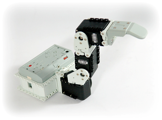 |
Download Assembly Check Task Code Download Task Code Download Video DYNAMIXEL Setting: AX-12+ ID[1, 2, 3]: Wheel Mode- It will rotate its arms rightward, if you press the R button on CM-5. - It will rotate it arms leftward, if you press the L button on CM-5. - It will stretch its elbows, if you press the U button on CM-5. - It will bend over its elbows, if you press the D button on CM-5. - It will stretch its wrists, if you press the start button and U button at the same time. - It will bend over its wrists, if you press the start button and D button at the same time. |
9. Obstacle Detecting Car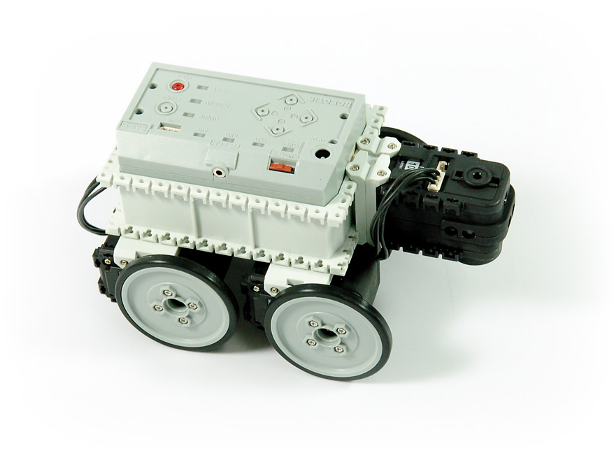 |
Download Assembly Check Task Code Download Task Code Download Video DYNAMIXEL Setting: AX-12+ ID[1, 2, 3, 4]: Wheel Mode, AX-S1 ID[100]- Operate the detecting car after installing obstacles on the driving path. - Detect obstacles by itself, and avoid them while driving. |
10. Greeting Penguin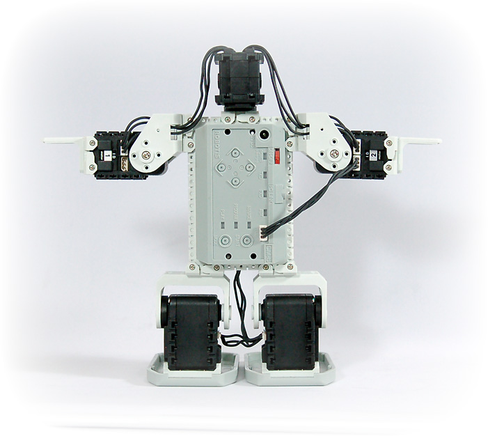 |
Download Assembly Check Task Code Download Task Code Download Video DYNAMIXEL Setting: AX-12+ ID[1, 2, 3, 4]: Joint Mode, AX-S1 ID[100]- If you put on your hands ahead of its head, it will bow. - If you put on your hands on the right side of its head, it will lift up its right hand. - If you put on your hands on the left side of its head, it will lift up its left hand. |
11. Attacking Duck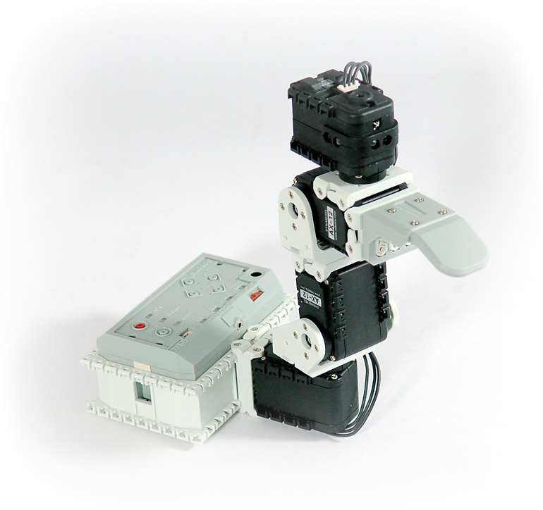 |
Download Assembly Check Task Code Download Task Code Download Video DYNAMIXEL Setting: AX-12+ ID[1, 2, 3]: Joint Mode, AX-S1 ID[100]- If you try to touch on its head with hands, it will attack using its beak. - If you touch on the right side of its head, it turns its head right. - If you touch on the left side of its head, it turns its head left. |
| 12. Cliff Detecting Car |
Download Assembly Check Task Code Download Task Code Download Video DYNAMIXEL Setting: AX-12+ ID[1, 2, 3, 4]: Wheel Mode, AX-S1 ID[100]- Operate the detecting car after installing cliffs and obstacles on the driving path. - Detects cliffs and obstacles by it self, and avoid them while driving. |
13. Clapping Penguin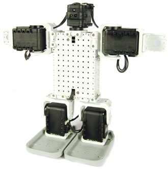 |
Download Assembly Check Task Code Download Task Code Download Video DYNAMIXEL Setting: AX-12+ ID[1, 2, 3, 4]: Joint Mode, AX-S1 ID[100]- It will bow, if you put your hands in front of its head. - It will clap as much times as your clapping sounds are heard. |
14. Waking Droid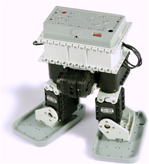 |
Download Assembly Check Task Code Download Task Code Download Motion File Download Video DYNAMIXEL Setting: AX-12+ ID[1, 2, 3, 4]: Joint Mode, AX-S1 ID[100]- Operate the walking droid, after installing obstacles on walking path. - Detect obstacles by itself and avoid them while walking by feet. |
References
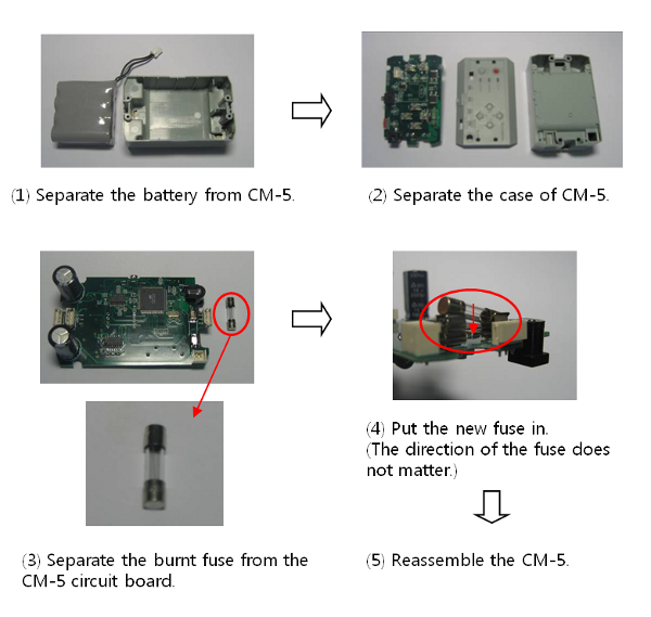
Replacing Fuse(CM-5)
The fuse prevents the over power that flows in the CM-5 which can damage the circuit. If the CM-5 does not turn on with the battery but turns on when connected to the SMPS, replace your fuse.
If the fuse is disconnected, followings will happen.
- Can turn on the power of CM-5 with SMPS only.
- The LED doesn’t blink even when you press the U button for charging.
The fuse used for CM-5 is available at electric shops( Fuse Volume : 220V/5A )
DYNAMIXEL Management
DYNAMIXEL used as robot actuators possess many functions. This section explains how to change the dynamixel’s settings.
Changing the ID
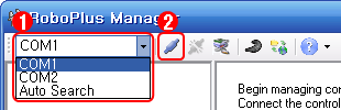
- Select the port the controller is connected to.
-
Click “Connect”.
- A list of connected dynamixels is shown on the left. Click on the dynamixel you wish to change the ID of.
- Click on the ID row in the Control Table.
-
Click on the ID List combo box to see a list of possible ID’s. Select the ID, then click Apply.
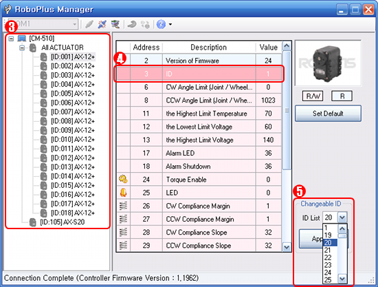
- To use in RoboPlus Motion and RoboPlus Task, the ID must be within the following ranges.
- The DYNAMIXEL’s ID must be between 0 and 25.
- The ID for AX-S1 should be set between 100 and 109.
Changing the Movement Mode
The dynamixel can operate in 2 different modes.
- Wheel Mode : Rotates 360 degrees like a regular motor.
- Joint Mode : Moves at a set angle with normal servo motors.
The mode can be changed using RoboPlus Manager. Once the mode is set, it will be maintained, even when turned off.
- Select the port the controller is connected to.
-
Click “Connect”.

- A list of connected DYNAMIXEL is shown on the left. Click on the DYNAMIXEL you wish to change the mode of. Then, click on the CW/CCW Angle Limit line in the Control Table.
-
To set to Wheel Mode, change the CW/CCW Angle Limit value to “0.” Or, simply click on the “Wheel Mode” button.
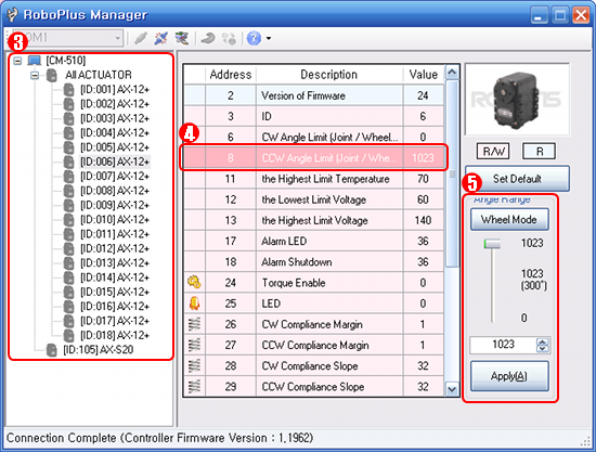
- To set to Joint Mode again, set the CW/CCW Angle Limit value to any number other than “0”. The initial values for Joint Mode are “0” for CW Angle Limit, and “1023” for CCW Angle Limit.
Troubleshooting
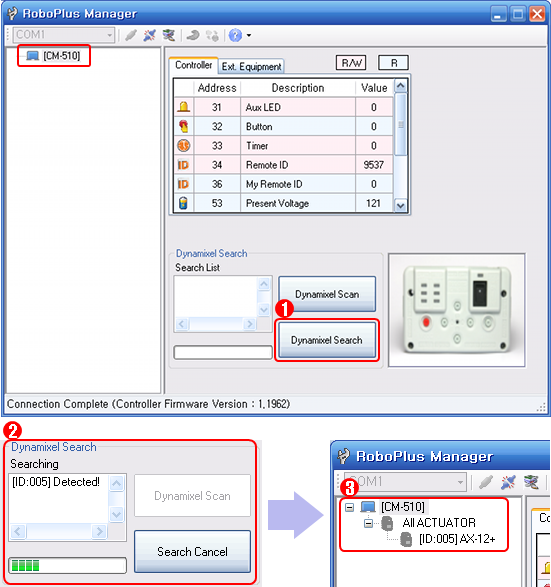
If you cannot find the dynamixel you are looking for using RoboPlus Manager, try the following :
- Connect just 1 DYNAMIXEL and check if there are any duplicate IDs. If you see a DYNAMIXEL on the left even though only 1 DYNAMIXEL is connected, there is a high probability of a duplicate ID. Change the ID immediately.
- If you are unable to find any DYNAMIXEL as in the image below, click on “DYNAMIXEL Search”. If the communication speed is not set to 1Mbps, the “DYNAMIXEL Search” function automatically resets the controller’s communication speed to 1Mbps to enable it to be recognized.
If the problem persists, your dynamixel may need repair. Please contact the service department of the company you purchased from.
ZIGBee Wireless Control
ZIGBee
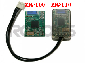
ZIG-100/110 uses ZIGBee for wireless communication. ZIGBee, like Bluetooth, is the communication technology commonly used in Personal Area Network (PAN). The communication quality of ZIGBee is better than that of IR, so it allows many users to control their robots without interferences.
CAUTION : Please note that not all products include a zigbee module and may need to be purchased separately.
Controller & ZIGBee
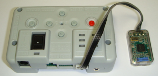
OLLO and Bioloid both use the RC-100, which uses IR communication method. To upgrade to the Zigbee communication method, you must purchase the ZIG-110 set separately. The ZIG-110 set includes one Zig-100 module, which is attached to the RC-100, and one Zig-110 module which is attached to the Controller.
NOTE : The modules in a single Zigbee set have been preconfigured to communicate with each other. Therefore, a module from one set may not work with a module from another set. Please be careful not to mix them up.
| ZIG-100 installed in RC-100 | ZIG-110 installed in CM-100 |
|---|---|
 |
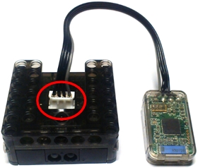 |
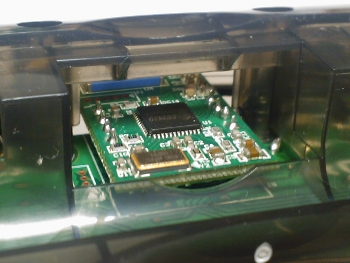
| ZIG-110 installed in CM-510 | ZIG-100 installed in CM-5 |
|---|---|
 |
 |
Control Multiple Robots
This method is to give out commands at once to several robots being used for dance or demonstration Gives out commands to the robot at once using the zigbee module’s broadcast mode
Bioloid(Entry/Advanced)
-
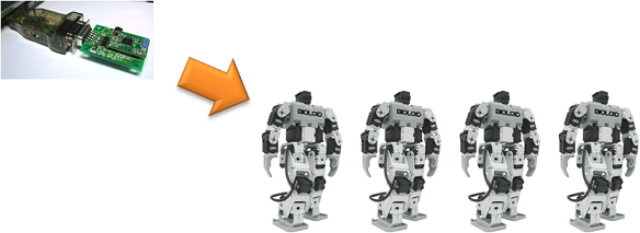
Communication with the Zig2Serial and various robots
-
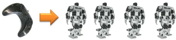
Communication with the RC-100 and various robots
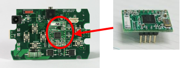
- To use the CM-5, connect the controller and ZIG-100 module together.
- Use the RoboPlus Manager to set the wireless ID of ZIG-100 module on the opposite party’s robot to 65535.
- No need to set the broadcast channel for communication.
- Use the RC-100 to give commands directly or use the Zig2Serial to give commands using the PC.
| Device | Channel Default Value | Whether or not the channel can be changed |
|---|---|---|
| CM-5 | 1 | Unchangeable |
| Zig2Serial | 1 | Changeable |
| RC-100 | 1 | Changeable |
The channel for the ZIG-100 mounted on the CM-5 is unchangeable. Thus, all users must set their channel to #1 for broadcast communication. All channels for the devises must pair to communicate.
Bioloid Premium Kit
-
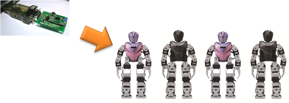
Communication with the Zig2Serial and various robots
-
Communication with the RC-100 and various robots
- When using the CM-510, connect the ZIG-100 module with the controller.
- Use the RoboPlus Manager to change the opposite party’s wireless ID to 65535.
- The channel on the ZIG-110 connected to the controller it set to #4, so the channels on the Zig2Serial and RC-100 must be set to #4.
- How to change the RC-100 channel
- How to change the Zig2Serial channel
| Device | Channel Default Value | Whether or not the channel can be changed |
|---|---|---|
| CM-510 CM530 |
4 | Unchangeable |
| Zig2Serial | 1 | Changeable |
| RC-100 | 1 | Changeable |
The channel for the zigbee connected to the controller is not changeable. Thus, all users must set their channel to #4 for broadcast communicationAll channels for the devises must pair to communicate.