
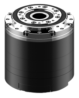
YM070-210-R051-RH
For initial setup refer to the instructions for Multi-turn Backup Battery Replacement to install and initialize the Multi-turn Backup Battery.
To resolve errors that occur during operation, please refer to Error Code(153) for information on the type of error and instructions on how to clear it
Specifications
| Item | Specifications |
|---|---|
| MCU | ARM Cortex-M4 (168 [Mhz], 32 [bit]) |
| Motor | Frameless BLDC |
| Baud Rate | 9,600 [bps] ~ 10,500,000 [bps] |
| Operating Modes | Position Control Mode Velocity Control Mode Current Control Mode |
| Weight | 790 [g] |
| Dimensions (W x H x D) | Ø70 x 71.1 [mm] |
| Hollow Shaft Size | Ø14[mm] |
| Resolution | 26,738,688 [pulse/rev] |
| Encoder Specifications | Single-Turn: 19Bit (524,288 [Pulse/Rev]) Multi-Turn: 18Bit (262,144 [Rev]) |
| Gear Ratio | 51:1 |
| Backlash | < 3.0 [arcmin] |
| Radial Load | 1,240 [N] (see the output bearing section) |
| Brake type | - |
| No Load Speed | 111.3 [rev/min] |
| Continuous Speed | 39.2 [rev/min] |
| Continuous Torque | 8.2 [N.m] |
| Continuous Current1) | 11.9 [A] |
| Maximum Torque2) | 16.3 [N.m] |
| Maximum Current1) 2) | 20.8 [A] |
| Output | 210 [W] |
| Input Voltage | 24 [V] |
| Operating Temperature | -5 ~ +55 [°C] |
| Command Signal | Digital Packet |
| Physical Connection | RS-485 Multidrop Bus RS-485 Asynchronous Serial Communication (8bit, 1stop, No Parity) |
| ID | 253 (0 ~ 252) |
| Standby Current | 40 [mA] |
- Current values are based on the phase current of the internal motor.
- The Maximum Torque and Current values represent the servo’s maximum instantaneous output. Continuous operation at or near these values will initiate an overload error to protect the device from damage.
Before Using the Product
- Please familiarize yourself with the contents of the manual before using the product. Operation of the product outside of intended usage or with incorrect assembly may cause vibration, shortened lifespan, and/or permanent damage to the actuator.
- Please verify that the model number and format match the product you are referencing.
- Ensure that all components are included in the product package.
- Check for any damage to the surface and appearance of the product.
- Before initial operation, connect the included Multi-turn Backup Battery and perform a multi-turn initialization.
![]()
Danger
(May cause serious injury or death.)
- Do not splash or pour flammable substances, surfactants, beverages, or water on, in, or around the product.
- Do not insert hands, feet, fingers, or any other body parts into the product during operation.
- If an unusual odor or smoke comes from the product, disconnect power immediately.
- Do not allow children to play with the product.
-
Always check the polarity of the power source before connecting or supplying power.
- The included lubricant may cause irritation of the skin or eyes with direct contact.
- In the event the lubricant comes into contact with your eyes, flush your eyes immediately with clean water and seek medical advice.
- In the event the lubricant comes into contact with your skin, wash your skin thoroughly with soap and water.
![]()
Warning
(May cause injury or damage to the product.)
- Please adhere to the product’s operating environment limitations. (Temperature: -5 ~ +55 [°C])
- Do not allow blades, sharp objects, sparks, and the like to be inserted or applied to the product during operation.
- The product is not intended to be disassembled or modified by the user.
-
Do not subject the product to strong impacts or drops.
- Be careful not to apply a load exceeding the allowable peak torque during operation.
- Prevent dust, chips, etc., from entering the product.
- While lubricant leakage prevention has been applied, the product may still be subject to leakage. Be sure to provide any additional protection treatments as needed according to your application.
- While anti-rust treatment has been applied, rust protection is not guaranteed, rust may still appear depending on storage and environmental conditions.
- This product is pre-packed with lubricant; do not mix with other lubricants.
- Please follow local government guidelines when disposing of the included lubricant.
![]()
Warning
(May cause injury or damage to the product.)
- Due to the material properties, rust may occur depending on the user environment.
- Repairs due to rust may incur costs, so please refer to the following guidelines to prevent rust.
- Please take steps to reduce humidity and improve ventilation.
- Salt removal and anti-corrosion treatment should be performed on a regular basis.
Warranty Coverage
- This product is covered under warranty for 1 year after the purchase date for usage under normal operating conditions.
- If there are any issues due to a manufacturing defect within the warranty period, ROBOTIS will repair or replace the product at no additional cost.
- Warranty will be void if the product is deemed to be used or handled improperly by the user.
- Warranty will be void if the product is taken apart, repaired, or modified in any way.
- Warranty will be void if the product is damaged by any external components.
- Warranty will be void in the case the product is affected by natural disasters and/or uncontrollable circumstances.
- ROBOTIS is not responsible for any damages or injuries resulting from product failure. Use at your own discretion.
Performance Graph
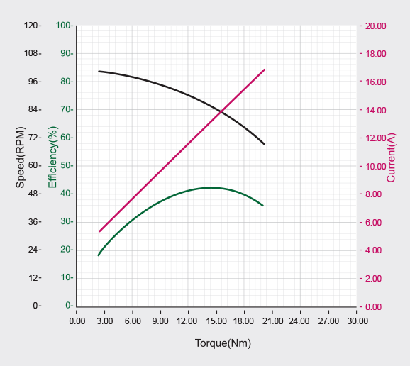
NOTE : The given Stall torque rating for a servo is different from it’s continuous output rating, and may also differ from it’s expected real world performance.
Stall torque is the maximum momentary torque output the servo is capable of, an is generally how RC servos are measured. The Performance graph, or N-T curve, from the above graph is measured under conditions simulating a gradually increasing load.
Generally, the Maximum Torque shown through Performance Graph testing is less than the maximum Stall Torque.
The actual real world performance of the servo will generally be closer to the performance graph measurements, not the rated stall torque.
CAUTION - When supplying power:
- Do not connect or disconnect DYNAMIXEL actuator cables while power is being supplied.
Control Table
The DYNAMIXEL control table is how the servo stores and represents its current state, as well as all of the data required for DYNAMIXEL configuration and control. DYNAMIXEL instruction packets allow users to read and write data to and from the control table to control the servo as well as monitor the device status.
Control Table, Data, Address
The Control Table is a structure that consists of multiple Data fields to store status or to control the device.
Each control table address is a unique value specified in Instruction Packets to access specific data in the Control Table. To read or write device data, you need to specify the corresponding address of the intended data in the Instruction Packet. For more detailed information about DYNAMIXEL packet structure, please refer to the DYNAMIXEL Protocol 2.0 eManual page.
Note: The representation of negative numbers follows the Two’s complement rule. For a detailed ㄷexplanation of Two’s complement, please refer to Wikipedia’s article on “Two’s complement.”
Area (EEPROM, RAM, Hybrid)
The control table is divided into three areas: EEPROM, RAM, and Hybrid. Here are the characteristics of each area:
| Area | Detai |
| EEPROM | Values in the EEPROM area are preserved even when the power is turned off. (Memory is Non-Volatile). The values in this area can only be altered when the value of Torque Enable (512) is '0' (Torque OFF). |
| RAM | The RAM area resets to its default values whenever power is applied (Memory is Volatile). The values in this area can be changed regardless of the value of Torque Enable. |
| Hybrid | The Hybrid area retains its values even when power is turned off, and changes can be made regardless of the Torque Enable value. When torque is disabled (Torque Enable = 0), it behaves like the EEPROM area. Values are immediately stored when changed. When torque is enabled (Torque Enable = 1), it behaves like the RAM area. Changes are possible but not immediately stored. To save changes made in this state, use Gain Save (170) when torque has been disabled. |
Size
Data consisting of 2 bytes or more may occupy multiple sequential control table registers up to 4 bytes long. When addressing control table data, the size of the control table item to be modified must be specified in the Instruction Packet to ensure proper data access.
Serial data with 2 bytes or more is represented in the control table using the Little Endian rule.
Access Authorization
Data in the control table has two access attributes. ‘RW’ indicates that both reading and writing are possible. ‘R’ indicates a read-only attribute. Data with a read-only attribute cannot have its value changed using WRITE Instructions.
Read-only attributes (‘R’) are primarily used for measurement or monitoring purposes, while read-write attributes (‘RW’) are used for device configuration and control.
Default Values
The default values in the EEPROM area as indicated in the manual are the initial settings of the product (factory default settings). When using the Factory Reset Instruction, any changes made by the user to the EEPROM will be reset to their default values.
The default values in the RAM area are the values set when power is supplied to the device.
Control Table Configuration
| Address | Size(Byte) | Modbus Address |
Area | Data Name | Access | Initial Value |
Range | Unit |
|---|---|---|---|---|---|---|---|---|
| 0 | 2 | 40001 | EEPROM | Model Number | R | 4,020 4,0211) |
4,020 (Dynamixel Protocol 2.0) 4,021 (Modbus) |
- |
| 2 | 4 | 40002 | EEPROM | Model Information | R | - | - | - |
| 6 | 1 | 40004 (Lo byte) | EEPROM | Firmware Version | R | - | - | - |
| 7 | 1 | 40004 (Hi byte) | EEPROM | ID | RW | 1 | 0 ~ 252 (Dynamixel Protocol 2.0) 0 ~ 247 (Modbus) |
- |
| 8 | 2 | 40005 | RAM | Bus Watchdog | RW | 0 | 0 ~ 127 | - |
| 10 | 1 | 40006 (Lo byte) | EEPROM | Secondary(Shadow) ID | RW | 255 | 0 ~ 252 | - |
| 11 | 1 | 40006 (Hi byte) | EEPROM | Protocol Type | RW | 2 10 |
2 (Dynamixel Protocol 2.0) 10 (Modbus) |
- |
| 12 | 1 | 40007 (Lo byte) | EEPROM | Baud Rate (Bus) | RW | 1 | 0 ~ 9 | - |
| 13 | 1 | 40007 (hi byte) | EEPROM | Return Delay Time | RW | 250 | 0 ~ 254 | 2 [us] |
| 15 | 1 | 40008 (hi byte) | RAM | Status Return Level | RW | 2 | 0 ~ 2 | - |
| 16 | 1 | 40009 (Lo byte) | RAM | Registered Instruction | R | 0 | 0 ~ 1 | - |
| 32 | 1 | 40017 (Lo byte) | EEPROM | Drive Mode | RW | 0 | 0 ~ 77 | - |
| 33 | 1 | 40017 (hi byte) | EEPROM | Operating Mode | RW | 3 | 0 ~ 3 | - |
| 34 | 1 | 40018 (Lo byte) | EEPROM | Startup Configuration | RW | 0 | 0 ~ 1 | - |
| 38 | 2 | 40020 | EEPROM | Position Limit Threshold | RW | 0 | 0 ~ 32,767 | 1 [pulse] |
| 40 | 4 | 40021 | EEPROM | In-Position Threshold | RW | 19 | 0 ~ 2,147,483,647 | 1 [pulse] |
| 44 | 4 | 40023 | EEPROM | Following Error Threshold | RW | 0 | 0 ~ 2,147,483,647 | 1 [pulse] |
| 48 | 4 | 40025 | EEPROM | Moving Threshold | RW | 19 | 0 ~ 2,147,483,647 | 5 [pulse/ms] |
| 52 | 4 | 40027 | EEPROM | Homing Offset | RW | 0 | -2,147,483,648 ~ 2,147,483,647 | 1 [pulse] |
| 56 | 1 | 40029 (Lo byte) | EEPROM | Inverter Temperature Limit | RW | 80 | 0 ~ 100 | 1 [°C] |
| 57 | 1 | 40029 (Hi byte) | EEPROM | Motor Temperature Limit | RW | 60 | 0 ~ 100 | 1 [°C] |
| 60 | 2 | 40031 | EEPROM | Max Voltage Limit | RW | 320 | 240 ~ 400 | 0.1 [V] |
| 62 | 2 | 40032 | EEPROM | Min Voltage Limit | RW | 160 | 160 ~ 400 | 0.1 [V] |
| 64 | 2 | 40033 | EEPROM | PWM Limit | RW | 1,000 | 0 ~ 1,000 | 0.1 [%] |
| 66 | 2 | 40034 | EEPROM | Current Limit | RW | 2,080 | 0 ~ 2,080 | 0.01 [A] |
| 68 | 4 | 40035 | EEPROM | Acceleration Limit | RW | 313 | 0 ~ 755,294 | 10 [rev/min²] |
| 72 | 4 | 40037 | EEPROM | Velocity Limit | RW | 3,921 | 0 ~ 12,592 | 0.01 [rev/min] |
| 76 | 4 | 40039 | EEPROM | Max Position Limit | RW | 262,144 | -2,147,483,648 ~ 2,147,483,647 | 1 [pulse] |
| 84 | 4 | 40043 | EEPROM | Min Position Limit | RW | -262,144 | -2,147,483,648 ~ 2,147,483,647 | 1 [pulse] |
| 96 | 4 | 40049 | EEPROM | Electronic GearRatio Numerator | RW | 51 | 1 ~ 1,045,576 | 1/R |
| 100 | 4 | 40051 | EEPROM | Electronic GearRatio Denominator | RW | 1 | 1 ~ 1,045,576 | R |
| 104 | 2 | 40053 | EEPROM | Safe Stop Time | RW | 200 | 0 ~ 32,767 | 1 [ms] |
| 106 | 2 | 40054 | EEPROM | Brake Delay | RW | 0 | 0 ~ 32,767 | 1 [ms] |
| 108 | 2 | 40055 | EEPROM | Goal Update Delay | RW | 0 | 0 ~ 32,767 | 1 [ms] |
| 110 | 1 | 40056 (Lo byte) | EEPROM | Overexcitation Voltage | RW | 100 | 0 ~ 100 | 1 [%] |
| 111 | 1 | 40056 (Hi byte) | EEPROM | Normal Excitation Voltage | RW | 0 | 0 ~ 100 | 1 [%] |
| 112 | 2 | 40057 | EEPROM | Overexcitation Time | RW | 0 | 0 ~ 32,767 | 1 [ms] |
| 132 | 2 | 40067 | EEPROM | Present Velocity LPF Frequency | RW | 0 | 0 ~ 32,767 | 0.1 [Hz] |
| 134 | 2 | 40068 | EEPROM | Goal Current LPF Frequency | RW | 0 | 0 ~ 32,767 | 0.1 [Hz] |
| 136 | 2 | 40069 | EEPROM | Position FF LPF Time | RW | 0 | 0 ~ 512 | 0.2 [ms] |
| 138 | 2 | 40070 | EEPROM | Velocity FF LPF Time | RW | 0 | 0 ~ 512 | 0.2 [ms] |
| 152 | 1 | 40077 (Lo byte) | RAM | Controller State | R | - | - | - |
| 153 | 1 | 40077 (Hi byte) | RAM | Error Code | R | - | - | - |
| 154 | 1 | 40078 (Lo byte) | RAM | Error Code History 1 | R | - | - | - |
| 155 | 1 | 40078 (Hi byte) | RAM | Error Code History 2 | R | - | - | - |
| … | … | … | … | … | … | … | … | … |
| 168 | 1 | 40085 (Lo byte) | RAM | Error Code History 15 | R | - | - | - |
| 169 | 1 | 40085 (Hi byte) | RAM | Error Code History 16 | R | - | - | - |
| 170 | 1 | 40086 (Lo byte) | RAM | Hybrid Save | RW | 0 | 0 ~ 2 | - |
| 212 | 4 | 40107 | Hybrid | Velocity I Gain | RW | 2,585,331 | 0 ~ 2,147,483,647 | - |
| 216 | 4 | 40109 | Hybrid | Velocity P Gain | RW | 26,184 | 0 ~ 2,147,483,647 | - |
| 220 | 4 | 40111 | Hybrid | Velocity FF Gain | RW | 0 | 0 ~ 2,147,483,647 | - |
| 224 | 4 | 40113 | Hybrid | Position D Gain | RW | 9,090 | 0 ~ 2,147,483,647 | - |
| 228 | 4 | 40115 | Hybrid | Position I Gain | RW | 0 | 0 ~ 2,147,483,647 | - |
| 232 | 4 | 40117 | Hybrid | Position P Gain | RW | 6,283,185 | 0 ~ 2,147,483,647 | - |
| 236 | 4 | 40119 | Hybrid | Position FF Gain | RW | 0 | 0 ~ 2,147,483,647 | - |
| 240 | 4 | 40121 | Hybrid | Profile Acceleration | RW | 313 | 0 ~ Acceleration Limit(68) | 10 [rev/min²] |
| 244 | 4 | 40123 | Hybrid | Profile Velocity | RW | 3,921 | 0 ~ Velocity Limit(72) | 0.01 [rev/min] |
| 248 | 4 | 40125 | Hybrid | Profile Acceleration Time | RW | 400 | 0 ~ 262,144 | 0.2 [ms] |
| 252 | 4 | 40127 | Hybrid | Profile Time | RW | 800 | 0 ~ 524,288 | 0.2 [ms] |
| 256 | 2 | N/A | EEPROM | Indirect Address 1 | RW | 634 | 8 ~ 919 | - |
| 258 | 2 | N/A | EEPROM | Indirect Address 2 | RW | 635 | 8 ~ 919 | - |
| … | … | … | … | … | … | … | … | … |
| 508 | 2 | N/A | EEPROM | Indirect Address 127 | RW | 760 | 8 ~ 919 | - |
| 510 | 2 | N/A | EEPROM | Indirect Address 128 | RW | 761 | 8 ~ 919 | - |
| 512 | 1 | 40257 (Lo byte) | RAM | Torque Enable | RW | 0 | 0 ~ 1 | - |
| 513 | 1 | 40257 (Hi byte) | RAM | LED | RW | 0 | 0 ~ 1 | - |
| 516 | 2 | 40259 | RAM | PWM Offset | RW | 0 | - Voltage(PWM)Limit(64) ~ Voltage(PWM)Limit(64) |
0.1 [%] |
| 518 | 2 | 40260 | RAM | Current Offset | RW | 0 | - Current Limit(66) ~ Current Limit(66) |
0.01 [A] |
| 520 | 4 | 40261 | RAM | Velocity Offset | RW | 0 | - Velocity Limit(72) ~ Velocity Limit(72) |
0.01 [rev/min] |
| 524 | 2 | 40263 | RAM | Goal PWM | RW | 0 | - Voltage(PWM) Limit(64) ~ Voltage(PWM)Limit(64) |
0.1 [%] |
| 526 | 2 | 40264 | RAM | Goal Current | RW | 0 | - Current Limit(66) ~ Current Limit(66) |
0.01 [A] |
| 528 | 4 | 40265 | RAM | Goal Velocity | RW | 0 | - Velocity Limit(72) ~ Velocity Limit(72) |
0.01 [rev/min] |
| 532 | 4 | 40267 | RAM | Goal Position | RW | 0 | Min Position Limit(84) ~ Max Position Limit(76) |
1 [pulse] |
| 541 | 1 | 40271 (Hi byte) | RAM | Moving Status | R | - | - | - |
| 542 | 2 | 40272 | RAM | Realtime Tick | R | - | - | 1[ms] |
| 544 | 2 | 40273 | RAM | Present PWM | R | - | - | 0.1 [%] |
| 546 | 2 | 40274 | RAM | Present Current | R | - | - | 0.01 [A] |
| 548 | 4 | 40275 | RAM | Present Velocity | R | - | - | 0.01 [rev/min] |
| 552 | 4 | 40277 | RAM | Present Position | R | - | - | 1 [pulse] |
| 560 | 4 | 40279 | RAM | Position Trajectory | R | - | - | 1 [pulse] |
| 564 | 4 | 40281 | RAM | Velocity Trajectory | R | - | - | 1 [pulse/s] |
| 568 | 2 | 40283 | RAM | Present Input Voltage | R | - | - | 0.1 [V] |
| 570 | 1 | 40284 (Lo byte) | RAM | Present Inverter Temperature | R | - | - | 1 [°C] |
| 571 | 1 | 40284 (Hi byte) | RAM | Present Motor Temperature | R | - | - | 1 [°C] |
| 634 | 1 | N/A | RAM | Indirect Data 1 | RW | 0 | 0 ~ 255 | - |
| 635 | 1 | N/A | RAM | Indirect Data 2 | RW | 0 | 0 ~ 255 | - |
| … | … | … | … | … | … | … | … | … |
| 760 | 1 | N/A | RAM | Indirect Data 127 | RW | 0 | 0 ~ 255 | - |
| 761 | 1 | N/A | RAM | Indirect Data 128 | RW | 0 | 0 ~ 255 | - |
| 919 | 1 | N/A | RAM | Backup Ready | R | - | - | - |
| N/A | 2 | 41001 | RAM | Factory Reset Instruction | W | - | - | - |
| N/A | 2 | 41002 | RAM | Reboot Instruction | W | - | - | - |
| N/A | 2 | 41003 | RAM | Clear Instruction | W | - | - | - |
Control Table Description
Caution: All data present in the EEPROM Area can only be modified when the value of Torque Enable (512) is ‘0’.
Model Number(0)
The model number of DYNAMIXEL indicates the protocol type. If the last digit of the model number is 0, it supports the DYNAMIXEL Protocol 2.0. If it is 1, it supports the Modbus Protocol. The protocol can be changed by firmware recovery to the corresponding protocol via the DYNAMIXEL Wizard 2.0 software. The following example demonstrates the model number and protocol information for the YM070-210-M001-RH model.
Example)
| Model | Model Number | Description |
|---|---|---|
| YM070-210-M001-RH | 4000 4001 |
Dynamixel Protocol 2.0 FW Modbus Protocol FW |
Model Information(2)
Additional DYNAMIXEL model information.
Firmware Version(6)
The firmware version installed on the DYNAMIXEL.
ID(7)
A unique number used to identify devices on the DYNAMIXEL network. The acceptable ID range is from 0 to 252 (0xFC), with 254 (0xFE) being reserved for the Broadcast ID. The Broadcast ID (254, 0xFE) is used specifically for sending Instruction Packets to all connected DYNAMIXEL devices simultaneously.
Caution : Each DYNAMIXEL servo connected to the network requires a unique ID. If device IDs are duplicated, communication errors can occur, and searching for DYNAMIXELs with duplicated IDs will fail.
Note : When a packet is sent to the Broadcast ID (0xFE), no status packets will be returned for read or write instructions regardless of the [Status Return Level(68)] setting. For more detailed information, please refer to the Status Packet section of the DYNAMIXEL Protocol 2.0 eManual page.
Bus Watchdog(8)
The [Bus Watchdog(8)] serves as a fail-safe mechanism to halt the device in case communication between the controller and the device is interrupted.
When Torque Enable(512) is ‘1’ (Torque is ON), the [Bus Watchdog(8)] feature monitors the interval of communication between the controller and the device. If the measured communication interval exceeds the configured [Bus Watchdog(8)] timer, the DYNAMIXEL will stop moving to ensure safety.
When this is triggered, the [Bus Watchdog(8)] value changes to ‘-1’ to indicate a Bus Watchdog Error. Once in the Bus Watchdog Error state, the Access attribute for Goal Values (Goal PWM(524), Goal Current(526), Goal Velocity(528), Goal Position(532) becomes Read-Only. Attempting to write a new value to these Goal Values will result in a Data Range Error, which will be indicated in the Status Packet’s Error field. To resolve the Bus Watchdog Error, you must reset [Bus Watchdog(8)] to ‘0’ or use the Error Clear Packet to clear the error.
Note : For detailed information about Data Range Errors, please refer to the DYNAMIXEL Protocol 2.0 eManual page.
Here is an example of how the Bus Watchdog function operates:
- Set [Operating Mode(33)] to Velocity Control Mode and change [Torque Enable(512)] to ‘1’.
- Write ‘50’ to [Goal Velocity(528)], to have the actuator begin to rotate counterclockwise.
- Change the value of [Bus Watchdog(8)] to ‘100’ (2,000 [ms]) to activate the Bus Watchdog feature.
- If no Instruction packet is received for 2,000 milliseconds, the device will come to a stop with a safe deceleration.
- The [Bus Watchdog(8)] value is set to ‘-1’ to indicate a Bus Watchdog Error, and the Access attribute of Goal Values becomes Read-Only.
- Writing ‘150’ to [Goal Velocity(528)], will result in a Data Range Error being reported via the Status Packet.
- Change the value of [Bus Watchdog(8)] to ‘0’ to clear the Bus Watchdog Error.
- Write ‘150’ to [Goal Velocity(528)], and the device starts rotating counterclockwise.
Secondary(Shadow) ID(10)
The [Secondary ID(10)] is another value that can be used to identify devices on the DYNAMIXEL network, similar to ID(7).
There are several important differences between ID(7) and [Secondary ID(10)]:
- The Secondary ID does not need to be a unique value. This means that multiple devices can share the same Secondary ID value, allowing the creation of device groups.
- The primary ID has a higher priority than the Secondary ID. If the Secondary ID and ID are the same, the primary ID takes precedence. You cannot use the Secondary ID to change values in the EEPROM area of the control table. Only values in the RAM area can be changed.
- If a command is sent to a servo’s Secondary ID, no Status Packet will be returned.
- If the value of the Secondary ID is 253 or higher, the Secondary ID functionality is disabled.
| Value | Description |
|---|---|
| 0 ~ 252 | Enable Secondary ID function |
| 253 ~ 255 | Disable Secondary ID function, Default value : ‘255’ |
Here is an example scenario with 5 devices with IDs ranging from 1 to 5:
- Set the Secondary ID (12) to ‘5’ for all 5 devices.
- Send a Write Instruction Packet (ID = 1, LED (513) = 255).
- The device with ID ‘1’ turns on its LED and returns a Status Packet.
- Send a Write Instruction Packet (ID = 5, LED (513) = 255):
- All 5 devices turn on their LEDs.
- However, only device ID ‘5’ returns a Status Packet.
- Set the Secondary ID (12) to ‘100’ for all 5 devices.
- Send a Write Instruction Packet (ID = 100, LED (513) = 0): All 5 devices turn off their LEDs. Since there is no device with ID ‘100’, no Status Packet is returned.
Protocol Type(11)
The communications protocol of the DYNAMIXEL-Y actuators can be set to either “DYNAMIXEL Protocol 2.0” or “Modbus-RTU.”
| Value | Description |
|---|---|
| 2 | DYNAMIXEL Protocol 2.0 |
| 10(TBD) | Modbus-RTU, Industrial Standard Protocol |
Note : The Modbus-RTU Protocol will be available for DYNAMIXEL-Y servos in the future.
Baud Rate (Bus)(12)
The Baud Rate is used to configure the communication speed for communication between the controller and servo over the RS-485 serial bus.
| Value | Nominal Baud Rate [bps] |
Actual Baud Rate [bps] |
Error Rate [%] |
|---|---|---|---|
| 9 | 10.5M | 10,500,000 | 0.000 |
| 8 | 6M | 6,000,000 | 0.000 |
| 7 | 4.5M | 4,421,053 | -1.176 |
| 6 | 4M | 4,000,000 | 0.000 |
| 5 | 3M | 3,000,000 | 0.000 |
| 4 | 2M | 2,000,000 | 0.000 |
| 3 | 1M | 1,000,000 | 0.000 |
| 2 | 115,200 | 115,226 | 0.023 |
| 1 (Default) | 57,600 | 57,613 | 0.023 |
| 0 | 9,600 | 9,600 | 0.000 |
Caution : Reliable Communication between the controller and the device requires a Baud rate error margin under 3%.
Note : When using a U2D2 reduce the response latency of the USB port to ensure stable communication at higher Baud rates.
Return Delay Time(13)
Return Delay Time allows the configuration of the delay time between a DYNAMIXEL receiving and executing an instruction packet and returning a status packet, in increments of two microseconds. For example, if the value is set to 10, a Status Packet will be returned after a delay of 20 microseconds.
| Unit | Range | Description |
|---|---|---|
| 2 [μsec] | 0 ~ 254 | Default: ‘250’ (500[us]) Maximum: ‘254’ (508[us]) |
Status Return Level(15)
Status Return Level is used to configure whether or the DYNAMIXEL will return status packets response to commands.
| Value | Response Policy | Description |
|---|---|---|
| 0 | PING Instruction | Status Packet is returned only in response to the PING command |
| 1 | PING Instruction Read Instruction |
Status Packet is returned only in response to PING and READ commands |
| 2 | All Instructions | Status Packet is returned for all commands |
Note: When the Instruction Packet is sent to the Broadcast ID (0xFE), Status Packets for Read Instruction or Write Instruction will not be returned regardless of the Status Return Level. For more detailed information, please refer to the Status Packet section of the DYNAMIXEL Protocol 2.0 eManual page.
Registered Instruction(16)
The Registered Instruction control table item indicates if there is a received Registered Write command ready to be executed.
| Value | Description |
|---|---|
| 0 | No registered command from REG_WRITE |
| 1 | Registered command from REG_WRITE |
Note: When the registered command is executed, the Registered Instruction value is reset to ‘0’.
Drive Mode(32)
Drive Mode contains a collection of DYNAMIXEL configuration settings related to actuator movement, including normal and reverse mode and the active profile setting.
| Value | Option | Description |
|---|---|---|
| Bit 7(0x80) | - | Unused, always ‘0’ ‘0’ |
| Bit 6(0x40) | Dynamic Brake ON | [0] Dynamic Brake OFF: Deactivate Dynamic Brake when torque is off. [1] Dynamic Brake ON: Activate Dynamic Brake when torque is off. |
| Bit 5(0x20) | - | Unused, always ‘0’ ‘0’ |
| Bit 4(0x10) | - | Unused, always ‘0’ ‘0’ |
| Bit 3(0x08) | - | Unused, always ‘0’ ‘0’ |
| Bit 2(0x04) | Profile Configuration | [0] Velocity-based Profile: Create profiles based on velocity. [1] Time-based Profile: Create profiles based on time. ※ For more details, refer to the Profile section of this eManual page. |
| Bit 1(0x02) | - | Unused, always ‘0’ ‘0’ |
| Bit 0(0x01) | Normal/Reverse Mode | [0] Normal Mode: Counter-clockwise (CCW) is positive, clockwise (CW) is negative. [1] Reverse Mode: Clockwise (CW) is positive, counter-clockwise (CCW) is negative. |
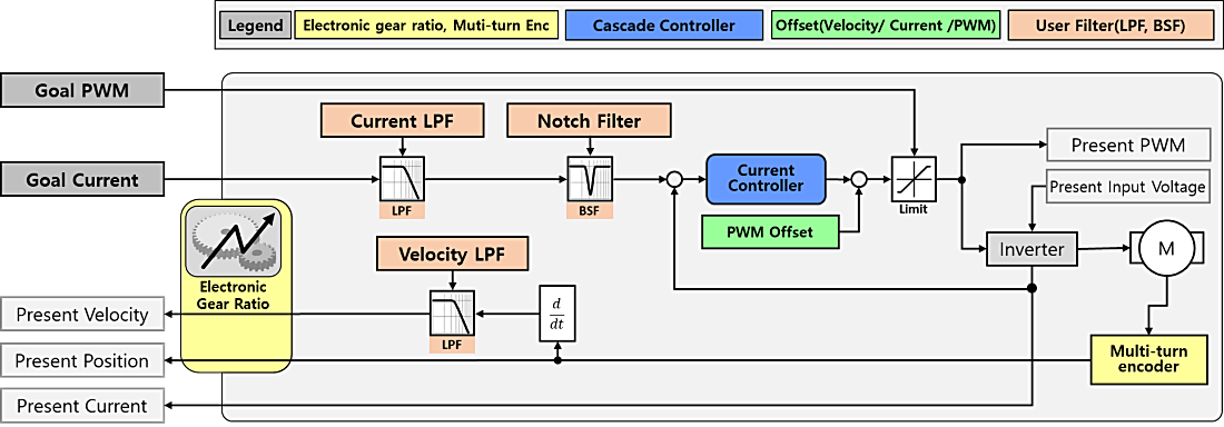
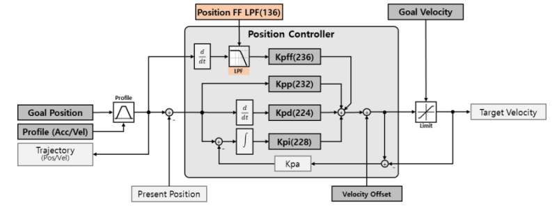
Operating Mode(33)
Operating Mode is used to configure the active DYNAMIXEL operating mode in use by the servo.
DYNAMIXEL-Y actuators support three control modes:
| Value | Operating Mode | Description |
|---|---|---|
| 0 | Current Control Mode | Controls current. Does not control velocity and position. |
| 1 | Velocity Control Mode | Controls velocity and current. Does not control position. |
| 3(Default) | Position Control Mode | Controls position, velocity, and current. Movement is restricted to within the range defined by Max and Min [Position Limit(84)]. |
The control block diagram for each control mode is as follows:
Current Control Mode
Velocity Control Mode
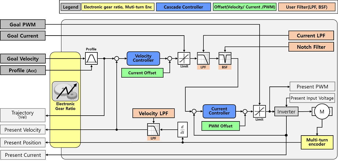
Position Control Mode
Note: DYNAMIXEL-Y stores persistent Multi-turn information. Even if the power is turned off and on, or if a Reboot Instruction is used, the current Multi-turn position is accurately tracked through even manual rotations while the power is off, and the absolute position value is updated. The Multi-turn position can be reset to ‘0’ using a Clear Instruction.
Startup Configuration(34)
Startup Configuration allows users to specify actions to be performed when the device is powered on.
| Value | Operating Mode | Description |
|---|---|---|
| Bit 7(0x80) | - | Unused, always ‘0’ ‘0’ |
| Bit 6(0x40) | - | Unused, always ‘0’ ‘0’ |
| Bit 5(0x20) | - | Unused, always ‘0’ ‘0’ |
| Bit 4(0x10) | - | Unused, always ‘0’ ‘0’ |
| Bit 3(0x08) | - | Unused, always ‘0’ ‘0’ |
| Bit 2(0x04) | - | Unused, always ‘0’ ‘0’ |
| Bit 1(0x02) | - | Unused, always ‘0’ ‘0’ |
| Bit 0(0x01) | Startup Torque ON | [0] Torque Enable set to ‘0’ (Torque Off) at boot-up [1] Torque Enable set to ‘1’ (Torque On) at boot-up |
Position Limit Threshold(38)
The Position Limit Threshold is the threshold for triggering Position Limit Reached Errors. If the value of Present Position(552) is outside the range of (Max Position Limit(76) + Position Limit Threshold) ~ (Min Position Limit(84) - Position Limit Threshold), a Position Limit Reached Error will be triggered. If this value is ‘0’, Position Limit Reached Errors are disabled.
| Unit | Range |
|---|---|
| 1 [Pulse] | 0 ~ 32,767 |
In-Position Threshold(40)
The threshold for determining the In-Position Bit of Moving Status(541). If the difference between the Goal Position(532) and Present Position(552) is smaller than this value, the In-Position Bit of the Moving Status(541) register will be set to ‘1’.
| Unit | Range |
|---|---|
| 1 [Pulse] | 0 ~ 2,147,483,647 |
Following Error Threshold(44)
The threshold value for determining the Following Error Bit of Moving Status(541). If the difference between Position Trajectory(560) and Present Position(552) is greater than this value, the Following Error Bit of the Moving Status(541) register will be set to ‘1’. If this value is ‘0’, the Following Errors are disabled.
| Unit | Range |
|---|---|
| 1 [Pulse] | 0 ~ 2,147,483,647 |
Moving Threshold(48)
The threshold value for determining the Moving Bit of Moving Status(541). If the Present Velocity(548) value is greater than this value, the Moving Bit of the Moving Status(541) register will be set to ‘1’.
| Unit | Range |
|---|---|
| 1 [Pulse] | 0 ~ 2,147,483,647 |
Homing Offset(52)
Used to adjust the zero position of the servo. This value is added to the actual position reported by the contactless encoder to produce the Present Position(552) value.
Present Position(552) = Actual Position + Homing Offset
| Unit | Range |
|---|---|
| 1 [Pulse] | -2,147,483,648 ~ 2,147,483,647 |
Inverter/Motor Temperature Limit(56, 57)
This is the upper limit for the operating temperature of the inverter and motor.
If the values of Present Inverter Temperature(570) or Present Motor Temperature(571) exceed the Inverter Temperature Limit and Motor Temperature Limit respectively, an overheating error occurs. The values of the control table items shown in the table below will be changed, and the device will enter an error state. After an error occurs, the next returned status packet will include an Alert Bit (0x80) in the Error field.
| Address | Label | Value Change | Description |
|---|---|---|---|
| 152 | Controller State | 9 (Hardware Fault) | The internal controller transitions to Hardware Fault state. |
| 153 | Error Code | 3 (Inverter Overheating) 4 (Motor Overheating) |
The temperature of the inverter is higher than the Inverter Temperature Limit(56). The temperature of the motor is higher than the Motor Temperature Limit(57). |
| 512 | Torque Enable | 0 (Torque OFF) | An error has occurred, causing the device’s torque to be disabled. |
| 154 ~ 169 | Error Code History | Error Code | The currently occurring error code is added to the Error Code History. |
Max/Min Voltage Limit(60, 62)
Min/Max Voltage Limit is used to configure the upper and lower limits of the input voltage.
If the Present Input Voltage(568) voltage exits the range between Max Voltage Limit or Min Voltage Limit, an input voltage error will be triggered. In such cases, the values in the control table are changed as shown in the table below, and the device comes to a stop. Since an error has occurred in the device, the next Status Packet transmitted will include an Alert Bit (0x80) in the Error field.
| Address | Label | Value Change | Description |
|---|---|---|---|
| 152 | Controller State | 9 (Hardware Fault) | The internal controller transitions to Hardware Fault state. |
| 153 | Error Code | 1 (Over Voltage Error) 2 (Low Voltage Error) |
The present input voltage is higher than the Max Voltage Limit. The present input voltage is lower than the Min Voltage Limit. |
| 512 | Torque Enable | 0 (Torque OFF) | An error has occurred, causing the device’s torque to be disabled. |
| 154 ~ 169 | Error Code History | Error Code | The currently occurring error code is added to the Error Code History. |
PWM Limit(64)
PWM Limit is used to configure the maximum PWM output by the servo. In all control modes, the servo will be limited a maximum PWM output equal to the configured PWM limit, and in PWM mode the Goal PWM(524) cannot be set to a value higher than the configured PWM Limit. Reducing the PWM limit will limit the maximum output torque and speed of the servo.
| Unit | Range | Description |
|---|---|---|
| 0.1 [%] | 0 ~ 1,000 | 500 = PWM Duty 50[%] Output 1,000 = PWM Duty 100[%] Output |
Caution : If the input voltage to the servo is less than 24v, output will be limited to the maximum input voltage.
Current Limit(66)
Current Limit is used to set the maximum output current in current controlled operating modes. The Goal Current(526) cannot be set to a value greater than the Current Limit. If a value greater than this limit is set, returned status packets will include a Data Limit Error in the Error field.
| Unit | Range | Description |
|---|---|---|
| 0.01 [A] | 0 ~ 2,080 | 1,000 = 10[A], 10[A] current limit 2,080 = 20.8[A], 20.8[A] current limit |
Note : Continuous currents exceeding the rated 10[A] can damage the actuator, and will trigger an Overload Error to protect the device. Only use currents exceeding the rated value for momentary periods.
Acceleration Limit(68)
Acceleration Limit allows the setting of a maximum acceleration value for trajectory generation. The Profile Acceleration(240) cannot be set to a value greater than the configured Acceleration Limit. If a value greater than this limit is set, the returned status packet will include a Data Limit Error in the Error field.
| Unit | Range |
|---|---|
| 10 [rev/min²] | 0 ~ 755,294 |
Velocity Limit(72)
Velocity limit is used to set an upper maximum on the speed of generated trajectories, as well as accepted Goal Velocity(528) values. Values for Goal Velocity(528) and Profile Velocity(244) cannot be set to values exceeding the Velocity Limit. If a value greater than this limit is set, the returned status packet will include a Data Limit Error in the Error field.
| Unit | Range | Description |
|---|---|---|
| 0.01[RPM] | 0 ~ 12,592 | 1,000 = Maximum speed limited to 10[RPM] 12,592 = Maximum speed limited to 125.92[RPM] |
Max/Min Position Limit(76, 84)
In Position Control mode, the Position Limits serves as a limit for target positions within the servo’s 32-bit range of motion (-2,147,483,648 ~ 2,147,483,647). In Position Control mode, the Goal Position(532) cannot exceed this value. If a value greater than this limit is set, the returned status packet will include a Data Limit Error in the Error field.
| Unit | Range |
|---|---|
| 1 [pulse] | -2,147,483,648 ~ 2,147,483,647 |
Electronic Gear Ratio Numerator/Denominator(96, 100)
The Electronic Gear Ratio allows the configuration of the number of motor pulses to your desired output scale, to ensure accurate position control even when the actuator is paired with an external reduction. The Electronic Gear Ratio is applied during the calculation of Present Velocity(548), Present Position(552), Goal Velocity(528), Goal Position(532), Position Trajectory(560) and Velocity Trajectory(564) calculation. The Electronic Gear Ratio is applied as follows when used in Position Control Mode:
Here is an example of electronic gear ratio configuration:
Re: Electronic Gear Ratio R: Actual Gear Ratio L: Ball Screw Lead
| System Form | Setting Unit | Description |
|---|---|---|
| Direct Drive System | 0.01 [deg] | DYNAMIXEL-Y Resolution: 524,288 [pulse/rev] |
| Gearbox Attachment R = 100:1 |
0.01 [deg] | DYNAMIXEL-Y Resolution: 524,288 [pulse/rev]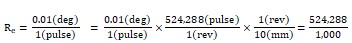 |
| Ball Screw System L: 10mm/rev |
0.01 [mm] | DYNAMIXEL-Y Pulse per 1Rev = 524,288 Resolution of DYNAMIXEL-Y: 524,288 [pulse/rev]  |
Torque ON-OFF Timing Chart
Timing Chart for the [Safe Stop Time(104)] ~ [Overexcitation Time(112)] features.
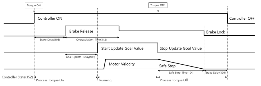
Note : When the Controller State(152) is Process Torque On(4) or Process Torque Off(6), writing values to Torque Enable(512), Goal PWM(524), Goal Current(526), Goal Velocity(528), Goal Position(532) will result in a “Result Fail” status packet return.
Safe Stop Time(104)
Safe Stop Time is used to configure the amount of time the actuator will use to decelerate if torque is disabled while the actuator is in motion. When the value of Torque Enable(512) is changed from ‘1’ (Torque ON) to ‘0’ (Torque OFF), the servo will stop operation and cut off the signal supplied to the inverter. If the device is in motion, it will decelerate to a stop according to the allotted time duration specified by Safe Stop Time to prevent damage.
| Unit | Range | Initial Value |
|---|---|---|
| [ms] | 0 ~ 32,767 | 200 |
Note : In Current Control mode, only Dynamic Brake deceleration is used to stop the actuator.
Brake Delay(106), Goal Update Delay(108)
Brake Delay allows the configuration of the delay time between torque being enabled or disabled and the brake system engaging, and Goal Update Delay allows configuration of the time between the brake disengaging and the controller updating registered goal values.
| Address | Label | Unit | Range | Description |
|---|---|---|---|---|
| 106 | Brake Delay | [ms] | 0 ~ 32,767 | Torque ON: The brakes will be released (106)[ms] after the Torque Enable(512) value is changed to 1. Torque OFF: The motor controller will turn off 100[ms] after the brake is enabled. |
| 108 | Goal Update Delay | [ms] | 0 ~ 32,767 | Updating of Goal Position, Velocity, Current, and PWM values begins Goal Update Delay[ms] after brake release. |
Overexcitation Voltage(110), Normal Excitation Voltage(111), Overexcitation Time(112)
These values are used for adjusting brake input voltage. Overexcitation Voltage sets the initial voltage used to disengage the brake system, Normal Excitation Voltage sets the voltage used to maintain brake disengagement, and Overexcitation Time sets the duration of the overexcitation period during brake disengagement.
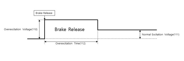
| Item | Unit | Range |
|---|---|---|
| Overexcitation Voltage | 1.0 [%] | 0 ~ 100 |
| Normal Excitation Voltage | 1.0 [%] | 0 ~ 100 |
| Overexcitation Time | 1.0 [ms] | 0 ~ 32,767 |
Present Velocity LPF Frequency(132)
The frequency of the Low-Pass Filter used to smooth the generation of Present Velocity(548). This is the setting to define the Present Velocity Filter in the Operating Mode(33) block diagram. Adjusting this value can lead to improved control performance if there is noise in the calculated velocity value.
| Unit | Range |
|---|---|
| 0.1[Hz] | 0 ~ 65,535 |
Goal Current LPF Frequency(134)
The frequency of the Low-Pass Filter for Target Current. This is used to define the Goal Current Filter in the Operating Mode(33) block diagram. Control performance may be improved by reducing unwanted frequencies from the control signal.
| Unit | Range |
|---|---|
| 0.1[Hz] | 0 ~ 65,535 |
Position FF LPF Time(136)
The frequency of the Low-Pass Filter for the Feedforward value of the Position Controller. Control performance may be improved by reducing unwanted frequencies in the control signal.
| Unit | Range |
|---|---|
| 0.2[ms] | 0 ~ 512 |
Velocity FF LPF Time(138)
The frequency of the Low-Pass Filter for the Feedforward value of the Velocity Controller. Control performance may be improved by reducing unwanted frequencies from the control signal.
| Unit | Range |
|---|---|
| 0.2[ms] | 0 ~ 512 |
Controller State(152)
Controller State allows the monitoring of the current activity state of the internal motor controller.
| Value | Label | Description |
|---|---|---|
| 0 | Start | Power has been supplied to the device. |
| 1 | Init System | Device initialization in progress. |
| 2 | Inverter OFF | Torque is OFF, The inverter is turned OFF. |
| 3 | Dynamic Brake | Torque is OFF, Dynamic Brake is active. |
| 4 | Processing Torque ON | Operations to enable Torque are in progress. |
| 5 | Running | Torque is ON. |
| 6 | Processing Torque OFF | Operations to disable Torque are in progress. |
| 7 | Detected HW Fault | A Hardware issue has been detected, and the servo is entering a fault state. |
| 8 | HW Fault | A Hardware issue has occurred. The issue can be identified using the Error Code(153) control table item. |
Note : When the Controller State is Processing Torque On(4) or Processing Torque Off(6), writing values to Torque Enable(512), Goal PWM(524), Goal Current(526), Goal Velocity(528), Goal Position(532) cannot be processed, and will result in a “Result Fail” return status packet.
Error Code(153)
Error Code stores the value of any currently active error statuses. The list of errors that may occur is as follows:
| Value | Label | Torque ON | *Hold | Error Clear | Description |
|---|---|---|---|---|---|
| 0 (0x00) | No Error | - | - | - | No error |
| 1 (0x01) | Over Voltage Error | N | - | Y | Device supply voltage exceeds the Max Voltage Limit(60) |
| 2 (0x02) | Low Voltage Error | N | - | Y | Device supply voltage exceeds the Min Voltage Limit(62) |
| 3 (0x03) | Inverter Overheating Error | N | - | Y | The inverter temperature has exceeded the Inverter Temperature Limit(56) |
| 4 (0x04) | Motor Overheating Error | N | - | Y | The motor temperature has exceeded the Motor Temperature Limit(57). |
| 5 (0x05) | Overload Error | N | - | Y | Operating current exceeding rated current for an extended duration |
| 7 (0x07) | Inverter Error | N | - | N | An issue has occurred with the inverter |
| 9 (0x09) | Battery Warning | Y | N | N | Low Multi-turn battery voltage. Replacement recommended |
| 10 (0x0A) | Battery Error | N | - | N | Multi-turn battery voltage is too low, causing issues |
| 11 (0x0B) | Magnet Error | N | - | N | Multi-turn position lost. Multi-turn reset required |
| 12 (0x0C) | Multi-turn Error | N | - | N | An issue has occurred with the Multi-turn IC |
| 13 (0x0D) | Encoder Error | N | - | N | An issue has occurred with the Encoder IC |
| 14 (0x0E) | Hall Sensor Error | N | - | N | An issue has occurred with the Hall Sensor |
| 15 (0x0F) | Calibration Error | N | - | N | Cannot find calibration Data |
| 17 (0x11) | Following Error | Y | Y | Y | Position control error exceeds the Following Error Threshold(44) |
| 18 (0x12) | Bus Watchdog Error | Y | Y | Y | An issue has occurred with the Bus Watchdog |
| 19 (0x13) | Over Speed Error | Y | Y | Y | Rotates at a speed of 120% or more than the Velocity Limit(72) |
| 20 (0x14) | Position Limit Reached Error | Y | Y | Y | In position control mode, the current position has moved beyond the Max/Min Position Limit + Position Limit Threshold(38) range. |
Note : *Hold indicates that writing new Goal Values is not possible while Torque is On and this error is in effect. In position and velocity control modes, the current position is maintained after deceleration and stop, while in current control mode, the servo will enter Dynamic Brake mode.
How to Clear Error
Many errors reported in the Error Code register can be cleared without requiring a reset of the actuator by using either of the methods below:
- Error Clear Packet: Errors that can be cleared can be reset by sending an Error Clear Packet.
- DYNAMIXEL Wizard 2.0: You can clear the error by pressing the Clear button located next to the Error Code on the right of the screen.
![]()
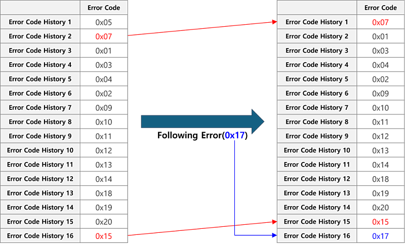
Error Code History
When a problem occurs with the device, the Error Code (153) is displayed, indicating the specific error. If an error occurs while the Error Code (153) value is not ‘0’ (No Error) due to a previous error, the value of Error Code (153) will be changed to the corresponding error value. In other words, the value of Error Code (153) indicates the most recent error occurred. In such cases, the Error Code (153) that occurred in Error Code History 1 to 16 (154 ~ 169) are stored sequentially.
Note : The same error does not occur multiple times.
If more than 16 errors occur, the oldest errors (Error Code History 1 (154)) are deleted, and the 16 most recent error values are recorded. The following is an example when 16 errors have occurred, and the 17th error occurs.
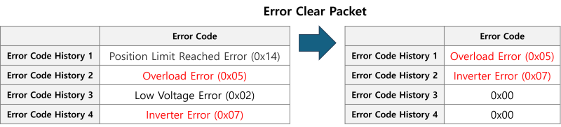
When clearing Error Code (153) via the Error Clear Packet, the errors that can be cleared from Error Code History 1 ~ 16 are removed, while those that cannot be cleared remain. The following is an example of sending an Error Clear Packet when clearable and impossible errors are recorded in the Error Code History.
Hybrid Save(170)
Hybrid Save indicates whether or not the Hybrid memory area has been modified since it was last saved, and allows requesting saves of the hybrid memory area. Writing ‘1’ to this control table item will save the current values of the hybrid memory to storage.
| Value | Label | Description |
|---|---|---|
| 0 | Changed | There are unsaved values in the Hybrid area. |
| 1 | Save Request | Request to save values in the Hybrid area. This can only be requested when the Torque Enable(512) value is ‘0’. |
| 2 | Saved | The values in the Hybrid area have been saved. |
Note : If the value of Hybrid Save is ‘0’, changes to hybrid memory will not be saved if the device is rebooted or power is disconnected.
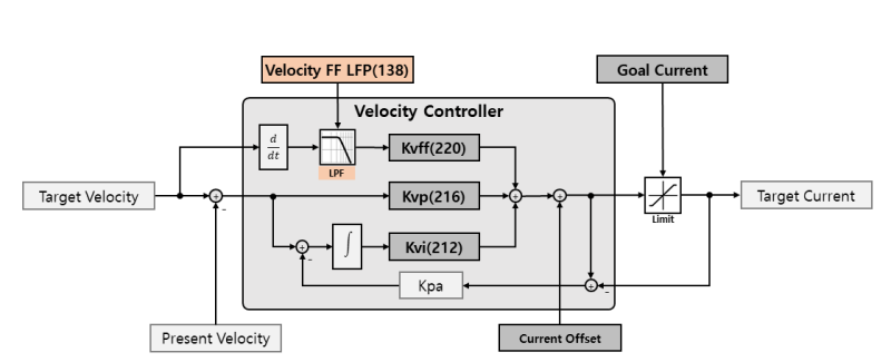
Velocity I Gain(212), Velocity P Gain(216), Velocity FF Gain(220)
These are the control gain values for the internal velocity controller used to generate velocity trajectories in the Velocity Controller block within the block diagram of the Operating Mode(33) item.
| item | Gain Notation | Range | Description |
|---|---|---|---|
| Velocity I Gain(212) | KvI | 0 ~ 2,147,483,647 | Velocity Integral Gain |
| Velocity P Gain(216) | KvP | 0 ~ 2,147,483,647 | Velocity Proportional Gain |
| Velocity FF Gain(220) | KvFF | 0 ~ 2,147,483,647 | Acceleration Feedforward Gain |
Position D Gain(224), Position I Gain(228), Position P Gain(232), Position FF Gain(236)
These are the control gain values for the position controller. These values configure the Position Controller block within the block diagram of the Operating Mode(33).
| item | Gain Notation | Range | Description |
|---|---|---|---|
| Position D Gain(224) | KPD | 0 ~ 2,147,483,647 | Position Derivative Gain |
| Position I Gain(238) | KPI | 0 ~ 2,147,483,647 | Position Integral Gain |
| Position P Gain(232) | KPP | 0 ~ 2,147,483,647 | Position Proportional Gain |
| Position FF Gain(236) | KPFF | 0 ~ 2,147,483,647 | Velocity Feedforward Gain |
Profile Acceleration(240), Profile Velocity(244)
If a velocity-acceleration-based profile is selected as the Drive Mode(32), the Profile Acceleration and Profile Velocity will be used to generate and limit movement trajectories.
| item | Unit | Control Mode | Description |
|---|---|---|---|
| Profile Acceleration(248) | 10 [rev/min²] | Velocity control, Position control | Profile acceleration/deceleration time |
| Profile Velocity(252) | 0.01 [RPM] | Position control | Maximum movement speed of profile. If the value is 0, profiles are deactivated. |
Profile Acceleration Time(248), Profile Time(252)
If time-based profile is selected in Drive Mode(32), Profile Acceleration Time and Profile Time will be used to generate a time based movement trajectory. Please refer to the Profile section for further details.
| item | Unit | Control Mode | Description |
|---|---|---|---|
| Profile Acceleration Time(248) | 0.2 [ms] | Velocity control, Position control | Profile acceleration/deceleration time |
| Profile Time(252) | 0.2 [ms] | Position control | Total profile time. If the value is 0, the profile is deactivated. |
Indirect Address, Indirect Data
Indirect Addresses allow users to restructure the layout of a DYNAMIXEL’s control tables to better suit the needs of their application. By assigning a control table item to an Indirect Address, the Indirect Data location associated with that address will represent the data in the assigned control table register. For example, if you assign ‘513’ to Indirect Address 1(256) and write ‘1’ to Indirect Data 1(634), the LED will light up and the value of the LED(513) control table item will change to ‘1’. Additionally, when a value is written LED(513), the value of Indirect Data 1 will also be updated. In other words, by assigning an address to an Indirect Address, the Indirect Data for that address becomes a mirror of the assigned address.
Example 1 : Allocating LED(513) to Indirect Data 1(634).
- Set Indirect Address 1(256) to ‘513’.
- Change Indirect Data 1(634) to ‘1’ : The LED(513) value also changes to ‘1’, and the LED turns on.
- Change Indirect Data 1(634) to ‘0’ : The LED(513) value also changes to ‘0’, and the LED turns off.
Note : In order to allocate more than 2 bytes of data to an indirect address, the addresses of all data must be assigned to the indirect address, as shown in ‘Example 2’.
One thing to note is when setting a Control Table with a length of 2 bytes or more as an Indirect Address all bytes of the Control Table Item must be designated to sequential Indirect Addresses. For instance, if you wish to set Indirect Data 2 to mirror Goal Position(532), you must configure it as follows:
Example 2 : To allocate 4 byte Goal Position(532) to Indirect Data 2(635), all 4 consecutive bytes must be allocated.
- Indirect Address 2(258) : Write 532 which is the first address of Goal Position.
- Indirect Address 3(260) : Write 533 which is the second address of Goal Position.
- Indirect Address 4(262) : Write 534 which is the third address of Goal Position.
- Indirect Address 5(264) : Write 535 which is the fourth address of Goal Position.
- Write 4 byte desired position value of 250,961(0x0003D451) to Indirect Data 2 ~ 5 : The value of Goal Position(532) will reflect these changes and update to 250,961(0x0003D451).
| Indirect Data Address | Goal Position Address | Saved HEX Value |
|---|---|---|
| 635 | 532 | 0x51 |
| 636 | 533 | 0xD4 |
| 637 | 534 | 0x03 |
| 638 | 535 | 0x00 |
Torque Enable(512)
Controls Torque ON/OFF state. Setting the value to ‘1’ enables Torque state and prevents writing data in the EEPROM area. If Torque cannot be enabled, the Result Fail bit in the returned status packet will be set to ‘1’.
| Value | Description |
|---|---|
| 0 | Torque OFF |
| 1 | Torque ON |
LED(513)
LED controls the indicator LED on the back of the servo.
| Value | Description |
|---|---|
| 0 | Turns off the LED at the back of the device. |
| 1 | Turns on the LED at the back of the device. |
Note : The LED also functions as an indicator displaying the device’s current condition:
| Status | LED Operation |
|---|---|
| Boot-up | Single blink |
| Factory Reset | Four blinks |
| Alarm | Steady blinking |
| Bootloader Mode | Illuminated |
PWM/Current/Velocity Offset(516, 518, 520)
Offset values for Goal PWM, Current, and Velocity. These offsets will be applied to goal values provided to the servo.
| item | Unit | Control Mode | Description |
|---|---|---|---|
| PWM Offset(516) | 0.01[V] | Current control, Velocity control, Position control | Offset for PWM output value |
| Current Offset(518) | 0.01[A] | Velocity control, Position control | Offset for current output value |
| Velocity Offset(520) | 0.01[RPM] | Position control | Offset for velocity output value |
Goal PWM(524)
Goal PWM is used as an upper limiting value for the output PWM of the motor in all control modes. Supplied Goal PWM values cannot exceed the configured PWM Limit(64)
| Unit | Range | Control Mode | Description |
|---|---|---|---|
| 0.1 [%] | - PWM Limit(64) ~ PWM Limit(64) | Current control, Velocity control, Position control | 500 = Maximum output voltage limited to 50[%] 1,000 = Maximum output voltage limited to 100[%] |
Goal Current(526)
In current control mode, the Goal Current is used to specify the desired output current. In velocity control mode and position control mode, it functions as a limit on the current controller’s output current. Goal Current cannot exceed the configured Current Limit(66).
| Unit | Range | Control Mode | Description |
|---|---|---|---|
| 0.01 [A] | - Current Limit(66) ~ Current Limit(66) | Current control Velocity control, Position control |
800 = 8[A] Current output 500 = Maximum output current limited to 5[A] |
Note : If a current exceeding the device’s rated current is continuously applied to the motor, an Overload Error will occur. Please only use currents exceeding the rating momentarily.
Goal Velocity(528)
In velocity control mode, the Goal Velocity value is used to specify the target velocity value.
In position control mode, it is used to set a limit on the maximum movement velocity. Goal Velocity cannot exceed the configured Velocity Limit(72).
| Unit | Range | Control Mode | Description |
|---|---|---|---|
| 0.01 [RPM] | - Velocity Limit(72) ~ Velocity Limit(72) | Current control Velocity control Position control |
Unused 80,000 = Rotates at 800[RPM] speed 500,000 = Maximum rotational speed limited to 5,000[RPM] |
Note : If the electronic gear ratio is not 1, the Goal Velocity value will be multiplied by this ratio before being applied to the controller.
Goal Position(532)
The Goal Position is used to specify the target position in position control mode. The Goal Position is limited by the configured Min Position Limit(84) and Max Position Limit(76).
| Unit | Range | Control Mode | Description |
|---|---|---|---|
| 1[pulse] (Approx. 0.006866 deg) |
Min Position limit(84) ~ Max position limit(76) | Current control Velocity control Position control |
Unused 16,000 = Move to position 16,000 [pulse] |
Moving Status(541)
Provides additional information about the movement status of the actuator. The In-Position Bit(0x01) is only used in position control mode.
| Value | Item | Description |
|---|---|---|
| Bit 7 (0x80) | - | Unused, always ‘0’ ‘0’ |
| Bit 6 (0x40) | Position In Range | Whether the current position is within the range of Min Position limit(84) ~ Max position limit(76) 0 : Out of the Limit Range 1 : Within the Limit Range |
| Bit 5 (0x40) Bit 4 (0x40) |
Profile type(H) Profile type(L) |
The current profile type in use 11 : Trapezoidal profile 10 : Triangular profile 01 : Rectangular profile 00 : Profile unused (Step) |
| Bit 3 (0x08) | Following error | Whether or not the Position Trajectory(560) is being followed 0 : Follow 1 : Following error |
| Bit 2 (0x04) | Moving | Whether the device is rotating 0 : Standby status 1 : Movement detected |
| Bit 1 (0x02) | Profile ongoing | Whether the profile is in progress according to the Goal Position(532) command 0 : Profile complete 1 : Profile in progress |
| Bit 0 (0x01) | In-Position | Whether the Goal Position(532) has been reached 0 : Not reached 1 : Reached |
Note : A triangular velocity profile is set automatically when the Profile Velocity(244) is not reached under trapezoidal velocity profile conditions.
Realtime Tick(542)
A realtime counter of the uptime of the device. It can be used as a timestamp for packets, providing a more accurate time value than a PC.
| Unit | Range | Description |
|---|---|---|
| 1 [ms] | 0 ~ 32,767 | Time since the device booted. The value resets to ‘0’ after reaching 32,767. |
Present PWM(544)
The PWM Duty value currently applied to the device’s motor. For more details, please refer to Goal PWM(524).
Present Current(546)
Present Current reports the actual instantaneous current value flowing through the device’s motor. Please refer to Goal Current(526) for further details.
Present Velocity(548)
Present Velocity reports the current rotational velocity of the device. Please refer to Goal Velocity(528) for further details.
Present Position(552)
Present Position reports the current encoder position of the device. Please refer to Goal Position(532) for further details.
Position Trajectory(560)
Position Trajectory is the target position trajectory generated by the active profile. This value is only generated in position control mode. Please refer to Profile Velocity(244) for further details.
Velocity Trajectory(564)
Velocity Trajectory is the target velocity trajectory generated by the active profile. The behavior of this value may differ depending on the active operating mode:
- Velocity control mode : When the profile has been completed, the Velocity Trajectory will equal the Goal Velocity(528)
- Position control mode : Reports the target velocity trajectory to follow the current Position Trajectory(560). When the profile ends, the Velocity Trajectory will be set to ‘0’.
Please refer to Profile Velocity(244) for further details.
Present Input Voltage(568)
Reports the present voltage that is being supplied to the device. Please refer to Max/Min Voltage Limit(60, 62) for further details.
Present Inverter Temperature(570)
This is the current temperature of the motor’s inverter. Please refer to the Inverter Temperature Limit(56) for further details.
Present Motor Temperature(571)
The current internal temperature of the motor. Please refer to the Motor Temperature Limit(57) for further details.
Backup Ready(919)
Backup Ready indicates whether the actuator has a Backup of the control table saved to internal memory available for restoration using a Control Table Backup Packet.
Factory Reset, Reboot, Clear Instruction (Modbus)
This section pertains to the commands for requesting Factory Reset, Reboot, and Clear functions within a Modbus Protocol firmware.
These commands are not supported by the standard firmware. Below is a detailed explanation of each command, including its value range and description.
| Modbus Address | Name | Value range, descirption |
|---|---|---|
| 41001 | Factory Reset Instruction | 0x00FF (255): Initialize all values 0x0001 (1): Initialize all values except for the ID |
| 41002 | Reboot Instruction | Writing any value will cause a reboot |
| 41003 | Clear Instruction | 0x0100 (256): MT Initialization 0x0200 (512): Error Clear |
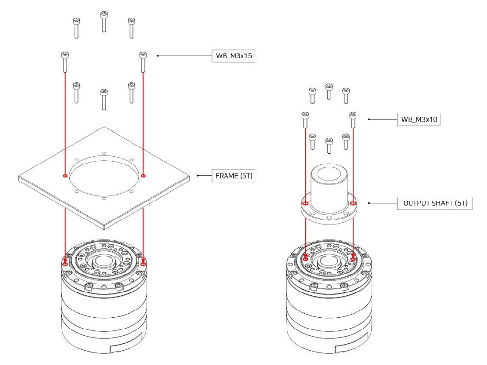
How to Assemble
Assembly Guide
Maintenance
Reference
Profile
Profiles are control methods used in motor operation to reduce rapid changes in speed and acceleration, thereby reducing vibrations, noise, and motor loads through controlled acceleration and deceleration. These profiles are often called Velocity Profiles as they directly control acceleration and deceleration based on target velocities. The device offers three types of profiles. Generally, the profile selection is determined by the combined settings of Profile Velocity(244) and Profile Acceleration(240). The trapezoidal profile specifically is additionally considers the total planned movement distance (ΔPos, the difference between the target position and the current position).
When the device’s controller receives an updated Goal Position(532), it generates a target velocity trajectory based on the actuator’s current movement speed. Even if the target position changes to a new Goal Position(532) while the device is in transit, the speed trajectory is adjusted to ensure smooth speed transition. The function responsible for creating a target velocity trajectory to prevent velocity discontinuity like this is called Velocity Override. Here, for simplicity in the formula, the initial speed of the profile is assumed to be ‘0’.
The following outlines the profile generation process for the Goal Position(532) command when the Operating Mode(33) is position control mode.
- The user’s request is registered as the new Goal Position(532) through the communication bus.
- The acceleration time (t1) is determined by the Profile Velocity(244) and Profile Acceleration(240).
- The shape of the profile is determined by the Profile Velocity(244), Profile Acceleration(240), and the total movement distance (ΔPos, the difference between the target position and the current position) as shown in the following table.
- The final selected profile is written to the Moving Status(541) register.
- The device moves according to the target trajectory calculated by the profile.
- The target velocity trajectory and target position trajectory of the chosen profile are written to the Position Trajectory(560) and Velocity Trajectory(564) registers.
| Condition | Types of Profile |
|---|---|
| Profile Velocity(244) = 0 | Profile unused (Step instruction) |
| (Profile Velocity(244) ≠ 0) & (Profile Acceleration(240) = 0) | Rectangular profile |
| (Profile Velocity(244) ≠ 0) & (Profile Acceleration(240) ≠ 0) | Trapezoidal profile |
Note : In velocity control mode, only Profile Acceleration(240) is used and the two available profile shapes are Step and Trapezoidal.
The Velocity Override function operates in a similar manner.
The acceleration time (t1) in this case is calculated as follows.
Velocity-based Profile : t1 = 64 * {Profile Velocity(112) / Profile Acceleration(108)}
Time-based Profile : t1 = Profile Acceleration(108)
Certifications
Please reach out to us at contactus2@robotis.com for certifications that are not listed.
FCC
% include en/dxl/fcc_class_b.md %}
Connector Information
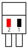
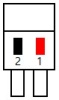
| Item | RS-485 | Power | ||
|---|---|---|---|---|
| Pinout | 1 DATA+2 DATA- |
1 GND2 VDD |
||
| Diagram |  |
 |
 |
 |
| Housing | 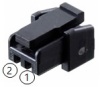 Molex 505565-0200 |
S/T type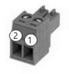 Molex 39500-0002 |
R/A type 1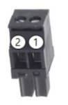 Molex 39503-2002 |
R/A type 2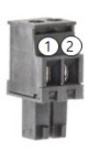 Molex 39503-3002 |
| PCB Header | 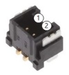 Molex 505568-0381 |
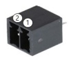 Molex 39501-1002 |
||
| Crimp Terminal | 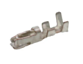 Molex 504185-1000 |
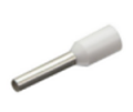 (Option) CE007508(0.75SQ, L14, P8) |
||
| Wire Specification | 26 AWG | 20 AWG |
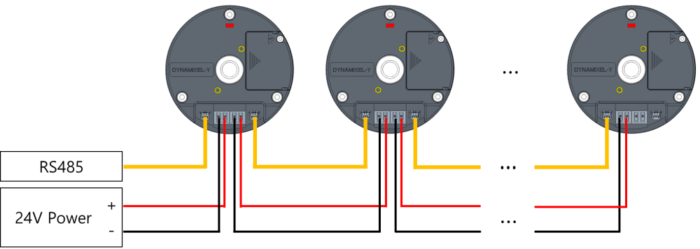
Caution: Before operation, ensure that 24V power is supplied through the power port. During setup, take special care to ensure that the polarity of all connections are correct. Incorrect connection may result in serious damage to the DYNAMIXEL.
Note: DYNAMIXEL-Y uses a new connector to enhance the utility of its hollow structure and ensure stable current supply and communication. The JST connector used in existing DYNAMIXEL models cannot reliably supply the current required to operate DYNAMIXEL-Y. Therefore, it is essential to use the designated connector.
Note: If communication between DYNAMIXEL-Y and U2D2 is unstable, please connect the GND of the power line to the GND of the U2D2.
Communication Circuit
UART Connection Circuit Diagram
DYNAMIXEL-Y servos require half-duplex RS-485 communications for control. In order to utilize a full-duplex RS-485 network to control DYNAMIXEL actuators a half-duplex conversion circuit is required. The diagram below details the recommended circuit diagram for half-duplex conversion.
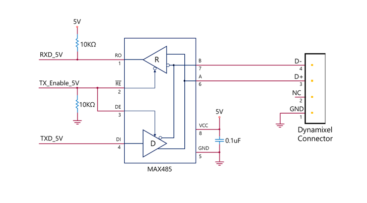
Note: The circuit above is suitable for MCUs with a 5V logic level, or which are otherwise 5V tolerant. For devices using other logic levels, use a Level Shifter to match the required operating voltage.
The above circuit is integrated into ROBOTIS’ DYNAMIXEL controllers. In the provided circuit diagram, the direction of the data signal of the TxD and RxD lines is determined based on the level of TX_Enable_5V.
- If TX_Enable_5V = High : The TxD signal is transferred to D+ and D-
- If TX_Enable_5V = Low : The D+ and D- signals are transferred to RxD
Cable Connection
The pin configuration of the DYNAMIXEL-Y connector is shown below.
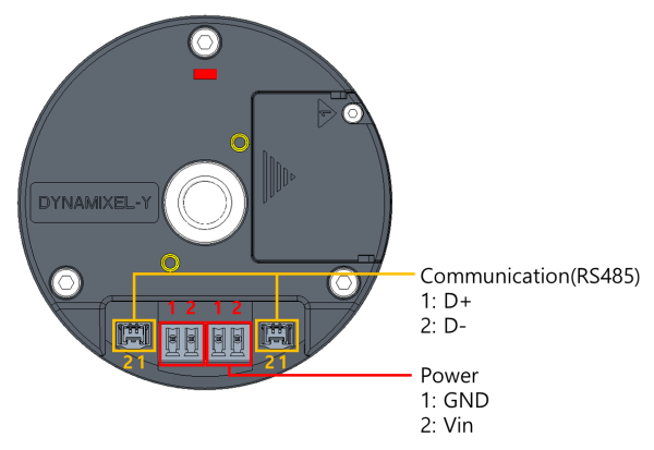
Drawings
Moment of Inertia
TBD
Please also checkout ROBOTIS Download Center for software applications, 3D/2D CAD, and other useful resources!
Clear Packet
Multi-turn Clear Packet
DYNAMIXEL-Y is capable of backing up Multi-turn position information, ensuring that it is preserved even after a power outage. A Multi-turn Clear Packet is required to reset this value. After a Multi-turn Clear, DYNAMIXEL will undergo a reboot.
After replacing the Multi-turn Backup Battery, it is essential to perform this process prior to resuming operation.
| Packet Type | P1 | P2 ~ P5 | Description |
|---|---|---|---|
| Multi-turn Clear | 0x01 | Fixed value (0x44 0x58 0x4C 0x22) |
Sets the current position (Present Position) value to an absolute position within one revolution based on the motor. Can be cleared only when the motor is not in motion. If the Clear Instruction Packet is sent while Torque Enable is active, the Error field in the Status Packet will display Result Fail (0x01). |
| Error Clear | 0x02 | Fixed value (0x45 0x52 0x43 0x4C) |
Clear errors that occurred in DYNAMIXEL. If an error cannot be cleared or the conditions for clearance are not met, the error remains uncleared, and Result Fail (0x01) is displayed in the Error field of the Status Packet. |
Note: Multi-turn Clear resets the motor’s absolute position value to within one revolution. Models with an attached reducer may lose their reducer-based absolute position. To prevent this issue, move the reducer’s absolute position to 0 before proceeding with the Multi-turn Clear process.
Multi-turn Clear Method
![]()
- Click the ‘Packet’ button at the top of DYNAMIXEL Wizard 2.0 to open the packet window. If connected to DYNAMIXEL, click ‘Disconnect’ to terminate the connection.
- Select the COM Port and Baud Rate in use for your servos, then click the ‘Open’ button.
- Select ‘Clear Instruction’ from the Instruction tab.
- Enter the DYNAMIXEL ID for the servo you wish to clear and click the ‘Send’ button to transmit the packet.
- Wait until the Status Packet is received. Check the received packet for errors before resuming operation of your servo.
Note: For more detailed information, please refer to the DYNAMIXEL Wizard 2.0 and DYNAMIXEL Protocol 2.0 eManual pages.
Error Clear Packet
The Error Clear Packet can be used to clear the error state of a DYNAMIXEL Y actuator without requiring a restart of the device. When there is an active error registered to the device, it can be cleared using a Clear Instruction Packet. If the error is unable to be cleared, the returned status packet will indicate a Failed result (0x01).
Multi-turn Backup Battery Replacement
DYNAMIXEL-Y features an internal Multi-turn Backup Battery for Multi-turn Position Backup. After replacing the battery, it is necessary to perform the Multi-turn Clear operation to reset the Multi-turn position to ensure accuracy.
Procedure for Battery Replacement
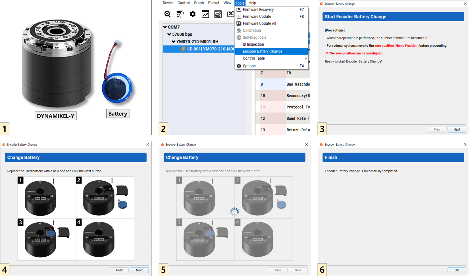
- Prepare the DYNAMIXEL-Y and new Multi-turn Backup Battery.
- After supplying power and connecting the DYNAMIXEL-Y to DYNAMIXEL Wizard 2.0, enter the Tools → Encoder Battery Replacement menu.
- In the case of a model with an included reducer, ensure that the reducer is positioned at it’s origin point. (Position 0)
- Open the battery cover, install the new Multi-turn Backup Battery, close the cover, and click the Next button.
- Set the multi-turn encoder mode. Note that a higher allowable angular acceleration will decrease battery life. Please set an appropriate value for your system.
- Once finished, exit the menu by clicking the OK button.
- Reset the Multi-turn to its initial state by sending the Multi-turn Clear Packet.
Output Bearing
Output bearing specifications (Table.B1)
| Model | Basic dynamic load rating, C [N] | Offset from flange, df [m] | Roller pitch circle diameter, Dp [m] | Allowable Dynamic equivalent radial load, Pc_max [N]1) | Allowable moment load, M_max [N.m]2) |
|---|---|---|---|---|---|
| YM070-210-R051-RH | 5,182 | 0.0086 | 0.0498 | 1677.1 | 44.5 |
| YM070-210-R099-RH | 5,182 | 0.0086 | 0.0498 | 2046.4 | 54.4 |
| YM080-230-R051-RH | 6,842 | 0.0093 | 0.0569 | 2091.3 | 63.0 |
| YM080-230-R099-RH | 6,842 | 0.0093 | 0.0569 | 2551.7 | 76.9 |
Note :
- Allowable dynamic equivalent load (Pc_max) must not exceed this value
- Allowable moment load, Ma is Lr+df=0 and La=0
Output bearing life
An estimate of the bearing life for the Dynamixel-Y output bearing can be calculated using the following equation:
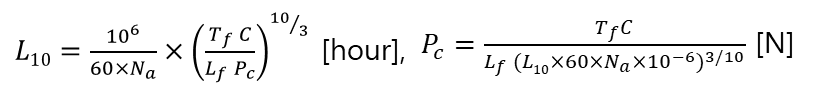
- L10 - Bearing life [hour]
- Na - Average output speed [rpm]
- C - Basic dynamic load rating [N]
- Pc - Dynamic equivalent load [N]
- Tf - Temperature factor (Tf=1.0 in environments of less than 100℃)
- Lf - Load factor (Available in Table.B2)
Allowable dynamic equivalent load, Pc_max

- L10 - Bearing life [hour] @ 7,000 hour
- Nn - Nominal output speed [rpm] @ input speed 2,000rpm ÷ gear ratio
- C- Basic dynamic load rating [N]
- Tf - Temperature factor (Tf=1.0 in environments of less than 100℃)
- Lf - Load factor (Available in Table.B2)
- Pc_max - Allowable dynamic equivalent radial load [N]
Dynamic equivalent load, Pc
The dynamic equivalent load of the Dynamixel-Y output bearing is obtained from the following equation.

- Pc - dynamic equivalent load [N]
- Fr - Radial load [N]
- Fa - Axial load [N]
- M - Moment [N.m]
- X - Dynamic radial factor (Available in Table.B3)
- Y - Dynamic axial factor (Available in Table.B3)
- Dp - Roller pitch circle diameter [m]
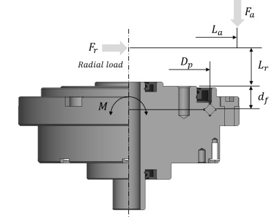
Allowable radial load, Fr_max
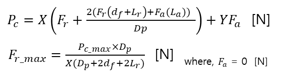
- Pc_max - Allowable dynamic equivalent load [N]
- Fa - Axial load [N]
- M - Moment [N.m]
- X - Dynamic radial factor (Available in Table.B3)
- Y - Dynamic axial factor (Available in Table.B3)
- Dp - Roller pitch circle diameter [m] (Table.B1)
- df - Offset from flange [m]
- Lr - Distance of radial load [m]
- Fr_max - Allowable radial load [N]
Tables
Table.B2 Load factor
| Conditions | Lf |
|---|---|
| Smooth motion without impact | 1.0 ~ 1.2 |
| Normal motion with occasional impact | 1.2 ~ 1.5 |
| Motion with severe impact | 1.5 ~ 3.0 |
Table.B3 Dynamic radial/axial factor
| Classification | X | Y |
|---|---|---|
| F_a/(F_r+2M/Dp)≤1.5 | 1.0 | 0.45 |
| F_a/(F_r+2M/Dp)>1.5 | 0.67 | 0.67 |
- If, Fr=0 and M=0, assuming X=0.67, Y=0.67