
IR Sensor Array
Introduction
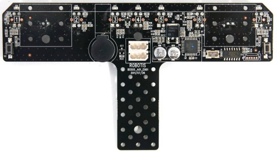
- The IR sensor array is a device with 7 mounted infrared sensors. Each IR sensor is capable of detecting black and white colors. The array is capable of emitting sounds.
- The IR array can perform detection at proper distances. The infrared sensors transmitters/receivers have optimal operating range of 0-5CM.
Specifications
| Item | Specifications |
|---|---|
| Weight | 18g |
| Resolution | 10bit(1,024) |
| Operation Temperature | -5°C ~ +85°C |
| Voltage | 7 ~ 15V (Recommended Voltage 11.1V) |
| Maximum Current | 100mA |
| Command Signal | Digital Packet |
| Protocol Type | Half duplex Asynchronous Serial Communication (8bit,1stop,No Parity) |
| Link (Physical) | TTL Level Multi Drop (daisy chain type Connector) |
| ID | 254 ID (0~253) |
| Communication Speed | 7,843bps ~ 1 Mbps |
| Feedback | Input Voltage, IR Sensor Data x 7 |
How to Use
LED
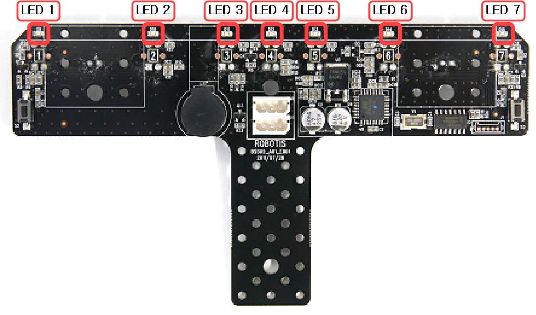
The LEDs will be turned on if the sensor value is smaller than the sensor value for black color detection.
Black Color Detecting Calibration
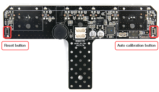
The 3-Pin connector provides power; pressing the right button initializes the array with set threshold values. Press the button one more time the arrays halts auto-calibration and reverts back to set threshold values. Set values = (MAX_VALUE + 2 * MIN_VALUE) / 3; where MAX_VALUE is max value of sensors between the first and second button presses, and MIN_VALUE is the min value of sensors between the first and second button presses.
Reset
Press the left button once and the IR array will reset via the supplied 3Pin cable. Note that this will not change set black detection values.
Communications Protocol
IR array communications and communications-related hardware are shown here.
- Comm protocal, packet component please refer to DYNAMIXEL comm.
- Comm hardware refer to the AX series.
Control Table
Control Table consists of data regarding the current status and operation, which exists inside of DYNAMIXEL. The user can control DYNAMIXEL by changing data of Control Table via Instruction Packet.
EEPROM and RAM
Data in RAM area is reset to the initial value whenever the power is turned on while data in EEPROM area is kept once the value is set even if the power is turned off.
Address
It represents the location of data. To read from or write data to Control Table, the user should assign the correct address in the Instruction Packet.
Access
DYNAMIXEL has two kinds of data: Read-only data, which is mainly used for sensing, and Read-and-Write data, which is used for driving.
Initial Value
In case of data in the EEPROM Area, the initial values on the right side of the below Control Table are the factory default settings. In case of data in the RAM Area, the initial values on the right side of the above Control Tables are the ones when the power is turned on.
Highest/Lowest Byte
In the Control table, some data share the same name, but they are attached with (L) or (H) at the end of each name to distinguish the address. This data requires 16bit, but it is divided into 8bit each for the addresses (low) and (high). These two addresses should be written with one Instruction Packet at the same time.
EEPROM Area
| Address | Data Name | Description | Access | Initial Value |
|---|---|---|---|---|
| 0(0x00) | Model Number(L) | Lowest Byte of Model Number | R | 74(0x4A) |
| 1(0x01) | Model Number(H) | Highest Byte of Model Number | R | 1(0x01) |
| 2(0x02) | Firmware Version | Firmware Version | R | - |
| 3(0x03) | ID | DYNAMIXEL ID | RW | 100(0x64) |
| 4(0x04) | Baud Rate | Communication Speed | RW | 1(0x0x) |
| 5(0x05) | Return Delay Time | Response Delay Time | RW | 250(0xFA) |
| 6(0x06) | IR Threshold_L 1 | Low Byte of IR Sensor #1 Threshold | RW | 16(0x10) |
| 7(0x07) | IR Threshold_H 1 | High Byte of IR Sensor #1 Threshold | RW | 3(0x03) |
| 8(0x08) | IR Threshold_L 2 | Low Byte of IR Sensor #2 Threshold | RW | 16(0x10) |
| 9(0x09) | IR Threshold_H 2 | High Byte of IR Sensor #2 Threshold | RW | 3(0x03) |
| 10(0x0A) | IR Threshold_L 3 | Low Byte of IR Sensor #3 Threshold | RW | 16(0x10) |
| 11(0x0B) | IR Threshold_H 3 | High Byte of IR Sensor #3 Threshold | RW | 3(0x03) |
| 12(0x0C) | IR Threshold_L 4 | Low Byte of IR Sensor #4 Threshold | RW | 16(0x10) |
| 13(0x0D) | IR Threshold_H 4 | High Byte of IR Sensor #4 Threshold | RW | 3(0x03) |
| 14(0x0E) | IR Threshold_L 5 | Low Byte of IR Sensor #5 Threshold | RW | 16(0x10) |
| 15(0x0F) | IR Threshold_H 5 | High Byte of IR Sensor #5 Threshold | RW | 3(0x03) |
| 16(0x10) | Status Return Level | Select Types of Status Return | RW | 2(0x02) |
| 17(0x11) | IR Threshold_L 6 | Low Byte of IR Sensor #6 Threshold | RW | 16(0x10) |
| 18(0x12) | IR Threshold_H 6 | High Byte of IR Sensor #6 Threshold | RW | 3(0x03) |
| 20(0x14) | IR Threshold_L 7 | Low Byte of IR Sensor #7 Threshold | RW | 16(0x10) |
| 21(0x15) | IR Threshold_H 7 | High Byte of IR Sensor #7 Threshold | RW | 3(0x03) |
RAM Area
| Address | Data Name | Description | Access | Initial Value |
|---|---|---|---|---|
| 24(0x18) | IR Data_L 1 | Low Byte of IR Sensor #1 Value | R | - |
| 25(0x19) | IR Data_H 1 | High Byte of IR Sensor #1 Value | R | - |
| 26(0x1A) | IR Data_L 2 | Low Byte of IR Sensor #2 Value | R | - |
| 27(0x1B) | IR Data_H 2 | High Byte of IR Sensor #2 Value | R | - |
| 28(0x1C) | IR Data_L 3 | Low Byte of IR Sensor #3 Value | R | - |
| 29(0x1D) | IR Data_H 3 | High Byte of IR Sensor #3 Value | R | - |
| 30(0x1E) | IR Data_L 4 | Low Byte of IR Sensor #4 Value | R | - |
| 31(0x1F) | IR Data_H 4 | High Byte of IR Sensor #4 Value | R | - |
| 32(0x20) | IR Data_L 5 | Low Byte of IR Sensor #5 Value | R | - |
| 33(0x21) | IR Data_H 5 | High Byte of IR Sensor #5 Value | R | - |
| 34(0x22) | IR Data_L 6 | Low Byte of IR Sensor #6 Value | R | - |
| 35(0x23) | IR Data_H 6 | High Byte of IR Sensor #6 Value | R | - |
| 36(0x24) | IR Data_L 7 | Low Byte of IR Sensor #7 Value | R | - |
| 37(0x25) | IR Data_H 7 | High Byte of IR Sensor #7 Value | R | - |
| 40(0X28) | Buzzer Data 0 | Buzzer Notes | RW | - |
| 41(0X29) | Buzzer Data 1 | Buzzer Ringing Time | RW | - |
| 42(0x2A) | Auto Threshold | Set Automatic Object Detection Mode | RW | 0(0x00) |
| 43(0x2B) | IR Obstacle Detected | IR Object Detection | R | - |
| 44(0X2C) | Registered | Registration of Instruction | RW | 0(0X00) |
| 47(0X2F) | Lock | Locking EEPROM | RW | 0(0X00) |
| 48(0X30) | IR Threshold_L 1 | Low Byte of IR Sensor #1 Set Value | RW | 16(0x10) |
| 49(0X31) | IR Threshold_H 1 | High Byte of IR Sensor #1 Set Value | RW | 3(0x03) |
| 50(0X32) | IR Threshold_L 2 | Low Byte of IR Sensor #2 Set Value | RW | 16(0x10) |
| 51(0X33) | IR Threshold_H 2 | High Byte of IR Sensor #2 Set Value | RW | 3(0x03) |
| 52(0X34) | IR Threshold_L 3 | Low Byte of IR Sensor #3 Set Value | RW | 16(0x10) |
| 53(0X35) | IR Threshold_H 3 | High Byte of IR Sensor #3 Set Value | RW | 3(0x03) |
| 54(0X36) | IR Threshold_L 4 | Low Byte of IR Sensor #4 Set Value | RW | 16(0x10) |
| 55(0X37) | IR Threshold_H 4 | High Byte of IR Sensor #4 Set Value | RW | 3(0x03) |
| 56(0X38) | IR Threshold_L 5 | Low Byte of IR Sensor #5 Set Value | RW | 16(0x10) |
| 57(0X39) | IR Threshold_H 5 | High Byte of IR Sensor #5 Set Value | RW | 3(0x03) |
| 58(0X3A) | IR Threshold_L 6 | Low Byte of IR Sensor #6 Set Value | RW | 16(0x10) |
| 59(0X3B) | IR Threshold_H 6 | High Byte of IR Sensor #6 Set Value | RW | 3(0x03) |
| 60(0X3C) | IR Threshold_L 7 | Low Byte of IR Sensor #7 Set Value | RW | 16(0x10) |
| 61(0X3D) | IR Threshold_H 7 | High Byte of IR Sensor #7 Set Value | RW | 3(0x03) |
Control Table Description
Model Number (0)
This address stores model number of DYNAMIXEL.
Firmware Version (2)
This address stores firmware version of DYNAMIXEL.
ID (3)
The ID is a unique value in the network to identify each DYNAMIXEL with an Instruction Packet. 0~252 (0xFC) values can be used as an ID, and 254(0xFE) is occupied as a broadcast ID. The Broadcast ID(254, 0xFE) can send an Instruction Packet to all connected DYNAMIXEL simultaneously.
NOTE : Please avoid using an identical ID for multiple DYNAMIXEL. You may face communication failure or may not be able to detect DYNAMIXEL with an identical ID.
NOTE : If the Instruction Packet ID is set to the Broadcast ID(0xFE), Status Packets will not be returned for READ or WRITE Instructions regardless of the set value of Stuatus Return Level (68). For more details, please refer to the Status Packet section for [DYNAMIXEL Protocol 2.0]
Baud Rate (4)
Baud Rate determines serial communication speed between a controller and DYNAMIXEL.
Available value range is 0 ~ 254(0xFE), and below is the equation for BPS calculation.
Baudrate(BPS) = 2,000,000 / (Value + 1)
| Value | Baud Rate(bps) | Margin of Error |
|---|---|---|
| 1 | 1M | 0.000 [%] |
| 3 | 500,000 | 0.000 [%] |
| 4 | 400,000 | 0.000 [%] |
| 7 | 250,000 | 0.000 [%] |
| 9 | 200,000 | 0.000 [%] |
| 16 | 115200 | -2.124 [%] |
| 34(Default) | 57600 | 0.794 [%] |
| 103 | 19200 | -0.160 [%] |
| 207 | 9600 | -0.160 [%] |
NOTE : Less than 3% of the baud rate error margin will not affect to UART communication.
NOTE : For the stable communication with higher Baudrate, configure USB Latency value to the lower.
USB Latency Setting
Return Delay Time (5)
If the DYNAMIXEL receives an Instruction Packet, it will return the Status Packet after the time of the set Return Delay Time(5).
Note that the range of values is 0 to 254 (0XFE) and its unit is 2 [μsec]. For instance, if the Return Delay Time(5) is set to ‘10’, the Status Packet will be returned after 20[μsec] when the Instruction Packet is received.
| Unit | Value Range | Description |
|---|---|---|
| 2[μsec] | 0 ~ 254 | Default value ‘250’(500[μsec]) Maximum value: ‘508’[μsec] |
IR Detecting Threshold
Set black values for IR #1 ~ #7 This value is referred when detecting black and white color.
| Values | Black detection | LED |
|---|---|---|
| Sensor value <= Threshold | BIT 1 | ON |
| Sensor value > set value | BIT 0 | OFF |
When the sensor is powered, the value in EEPROM area will be used to initialize RAM area Threshold.
IR sensor values (1 ~ 7)
If infrared light is emitted with enough intensity it will reflect off walls, objects, the receiver will detect the reflected light. Light reflected from bright walls and objects will be read as a high value. Measured value range is 0-1,023.
Infrared light measured from walls, objects, textures may be output differently including a difference in measurement.
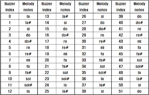
Buzzer Notes
A buzzer is installed in AX-S1, and simple beep sounds can be made. Total 52 musical notes can be made in Buzzer Notes, and various notes can be made because there are whole tones and halftones in each octave. The values of Buzzer Notes are assigned as the table below.
Buzzer Ringing Time
AX-S1 has a function to control the buzzer alarcming time. It is possible to control by the unit of 0.1 second, and the minimum length is set to 0.3 seconds; the time can be extended up to maximum 5 seconds. That is, if 0~3 is entered, the buzzer rings for 0.3 seconds; if the value over 50 is entered, the buzzer rings only for 5 seconds regardless of the value. Moreover, if the ringing is finished, the buzzer ringing time is automatically initialized to ‘0’. There are 2 special buzzer ringing time functions for AX-S1. Firstly, the buzzer can be ringing without stopping. If 254 is entered in buzzer ringing time, and the number of desired musical notes is entered, the buzzer rings without stopping. To stop the ringing, ‘0’ is entered in buzzer ringing time. Secondly, the buzzer can play special melodies. If 255 is entered in buzzer ringing time, and then the value 0~26 is entered in buzzer notes, 27 melodies corresponding to each number can be played. If the ringing is finished, the buzzer ringing time is automatically initialized to ‘0’.
Automatic set black detection mode
Mode for automatic black detection set-up from start to finish paramenters. From ‘0’ to ‘1’ starts; from ‘1’ to ‘0’ finishes.
In the IR array if each IR sensor detected black value is lower than the set black valuethe values will be assigned as shown below; the LED turns on.
| BIT | Name |
|---|---|
| Bit 0 | Black detection for IR sensor #1 |
| Bit 1 | Black detection for IR sensor #2 |
| Bit 2 | Black detection for IR sensor #3 |
| Bit 3 | Black detection for IR sensor #4 |
| Bit 4 | Black detection for IR sensor #5 |
| Bit 5 | Black detection for IR sensor #6 |
| Bit 6 | Black detection for IR sensor #7 |
Registered Instruction
| Value | Meaning |
|---|---|
| 0 | There are no commands transmitted by REG_WRITE |
| 1 | There are commands transmitted by REG_WRITE. |
NOTE : If ACTION command is executed, the value is changed into 0.
Lock
| Value | Meaning |
|---|---|
| 0 | EEPROM area can be modified. |
| 1 | EEPROM area cannot be modified. |
CAUTION : If Lock is set to 1, the power must be turned off and then turned on again to change into 0.