Introduction

ROBOTIS ENGINEER is the next generation robot that adopts AI technology based on smart devices.
- ROBOTIS ENGINEER Kit offers standardized curriculum for multi level robotics educational courses
- Joint structure allows diverse motions for versatile robots
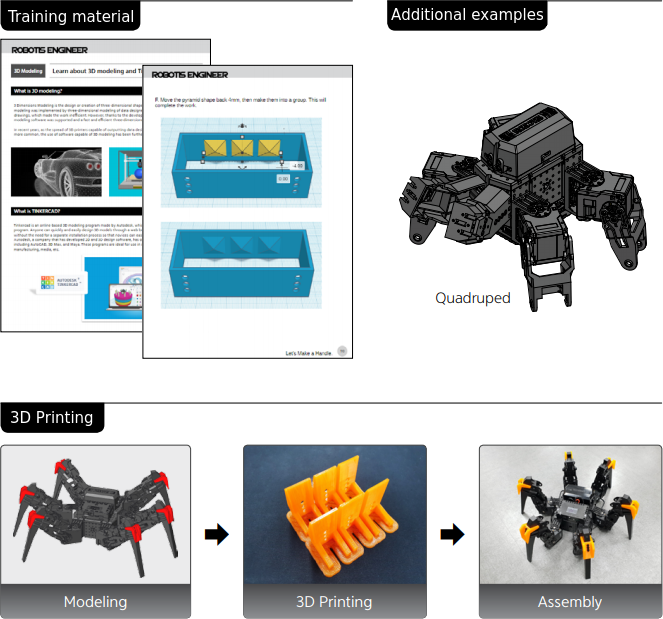
- Supports 3D part designing and printing
- Base kit includes parts to build 3 different robot figures (MAX, SPI, DR. R). Build up to 7 robot figures total with workbooks.
- Compatible with R+ ENGINEER(Smart device app), R+ Task 3.0(PC software)
- Upgrade to Raspberry Pi and Camera
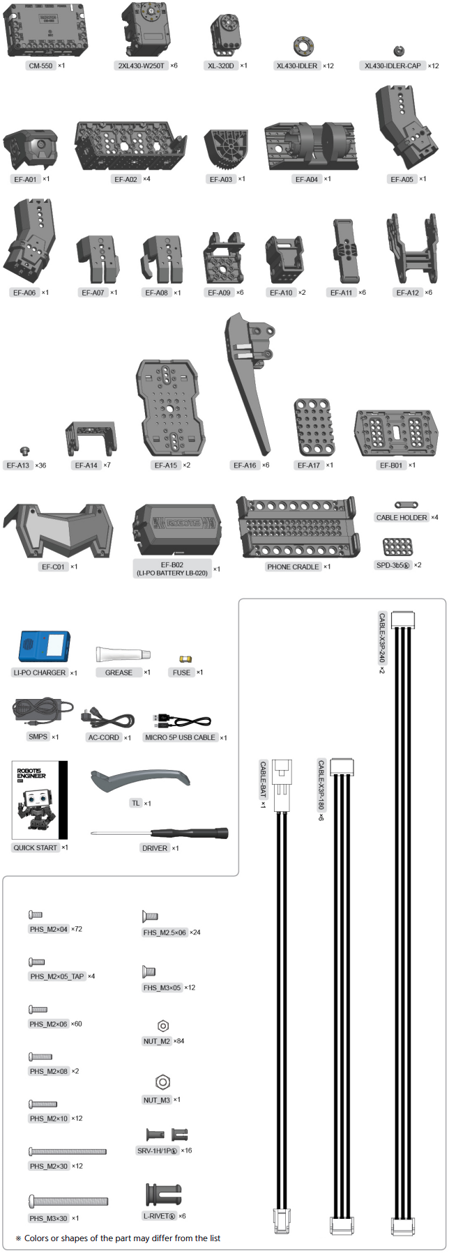
Parts List
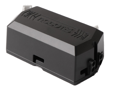
CM-550 Controller
Specifications
| Item | Specifications |
|---|---|
| Weight | 58.8 [g] |
| MCU | ARM Cortex-M4 (168 [MHz], 32 [Bit]) |
| Operating Voltage | Battery : 6.5 ~ 15 [V], Recommended 11.1 [V] (Li-PO 3cell) SMPS : 6.5 ~ 15 [V], Recommended 12.0 [V] Micro USB : 4.75 ~ 5.25 [V], Recommended 5.0 [V] |
| Current Consumption | Standby : 50 [mA] Port 1 ~ 2 I/O Max : 0.5 [A] Port 3 ~ 5 I/O Max : 0.02 [A] Total : 10 [A] (Fuse) |
| Operating Temperature | -5 ~ 70 [°C] |
| Communication Module | BLE Slave Module |
| Internal I/O Devices | Buttons : 2 (MODE, START) Mic (Sound Detection) : 1 Buzzer : 1 Voltage Sensor : 1 Gyro Accelerometer : 1 Temperature Sensor : 1 RGB LED : 3 |
| External I/O Devices | ROBOTIS 5 Pin Port : 5 (SM-10 / IR Array / TMS-10 : Use Port 1 or 2) X series DYNAMIXEL Ports : 6 |
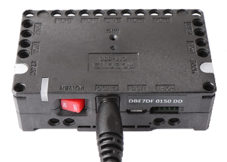
CM-550 Layout
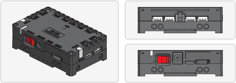
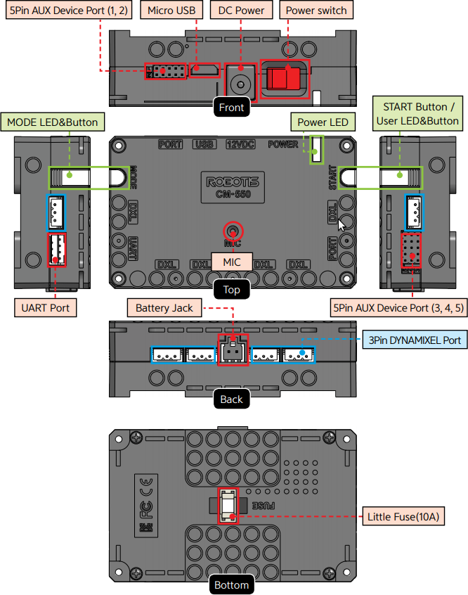
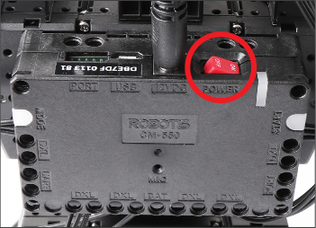
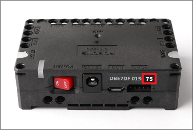
USBMicro USB Port : The 5 pin micro USB cable can be used to connect to the USB port of the PC.UARTCommunication Port : BT-210, BT-410, LN-101, IR receiver or other communication modules can be connected.BATBattery Socket : Provided Li-Po battery can be connected.12VDCDC Input : The DC barrel jack of provided SMPS can be connected.POWERPower Switch : Controls the power supply of the controller.- Status LED : Displays voltage level and wireless device connection status with RGB LED.
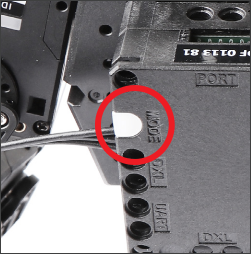
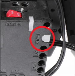
MODEMODE LED : This RGB LED displays the operating mode of CM-550. Please refer to the Operating Mode of CM-550.STARTSTART LED : Please refer to the Operating Mode of CM-550.MODEMODE Button : The operating mode can be changed with this button. Please refer to the Operating Mode of CM-550.STARTSTART Button : This button runs selected operating mode. Please refer to the Operating Mode of CM-550.DXLDYNAMIXEL-X Series Port : DYNAMIXEL-X series can be connected in any of these ports.PORTROBOTIS 5 Pin Port : Sensors such as DMS, Touch sensor, IR sensor can be connected.
Servo motor, IR array sensor, Temperature & Humidity sensor can only be connected to Port 1 or 2.MICInternal Microphone : The integrated microphone detects clapping sound.FUSEFuse : 10A fuse protects electric damage.
CAUTION : The USB port on CM-550 is designed to be connected with the PC. Please do NOT connect other USB devices, or it may cause damage to the controller.
See the more detail of CM-550 e-Manual
2XL430-W250 DYNAMIXEL
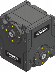
2XL430-W250 is a ground breaking DYNAMIXEL that allows to control 2 axis(2 DOF) with a single module. In order to control 2 axis at the same time, each axle is assigned with different ID while sharing an identical Baudrate. Since the Control Table for each axle is separated except the Baudrate, 2XL can be applied in various applications.
The usage is identical to other DYNAMIXEL’s, but be aware that Firmware Recovery will reset both axis to factory settings.
Cautions
Safety Precautions
![]()
- Read this manual carefully before getting started.
- Only use provided tools in the kit.
- Keep the robot away from the face and body when the robot is operating.
- Be careful for getting fingers or part of the body stuck in the robot joints.
- Do not operate or store the robot under the direct sunlight.
- Do not operate or store the robot near water or heat source.
- Do not tamper or disassemble components.
- Keep the robot and parts away from infants or younger children.
- Do not impact or poke the robot with sharp objects.
Precautions on Use
- Use provided screwdriver(PH 1) in the kit for tightening screws.
- Do not apply excessive force on screws and parts when assembling.
- Operate the robot on the floor to avoid any damages from falling.
- Accidental damages from falling is not covered by warranty.
- DYNAMIXEL internal gears and robot joints are expendables. Excessive use or long term use may develop the backlash.
- The robot in a rapid motion (i.e, a combat motion) consumes a lot of current momentarily and may cause the unexpected Power off due to the lack of provided power from its power source. In this case, please use a battery or SMPS with an high ampere (A) to prevent from the unexpected power off.
Precautions on Battery
![]()
- The battery must be disconnected from the robot when not used or charged with the designated charger.
- Do not disassemble or impact the battery or charger.
- Do not heat the battery and avoid contact with fire and liquids.
- Do not place battery in the microwave, laundry machine, refrigerator, or dryer.
- Do not use damaged batteries (deformed, swollen, external damages).
- Do not short the battery.
- Do not reverse the polarity of the battery when charging.
- Do not charge the battery when it is hot. Let the battery cools down to the room temperature before charging
- Do not store the battery in hot or humid place.
- Do not charge multiple batteries with the charger at the same time.
- Do not connect the battery to the charger when the charger is not connected to the power source.
Assembly Precautions
DYNAMIXEL Assembly
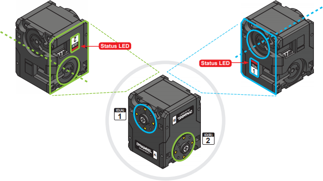
- In order to control 2 axis at the same time, each axle is assigned with different ID while sharing an identical Baudrate.
- The ID and Status LED is located on the opposite side of the output horn.
- ROBOTIS ENGINEER uses bolts to securely assemble the robot joints (Below image shows where bolts are required to attach the frame on DYNAMIXEL).
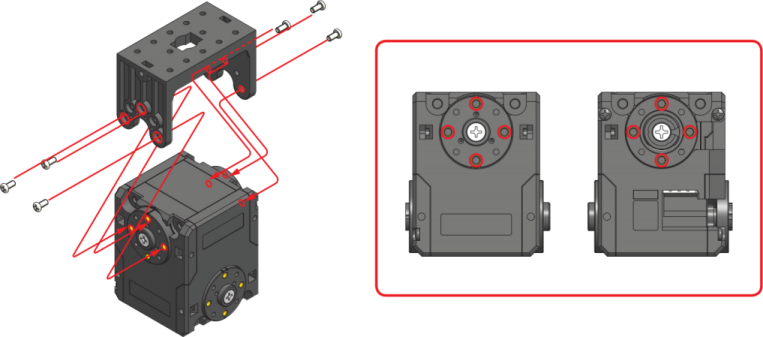
CAUTION : Please use the designated screw driver(PH 1) when assembling bolts.
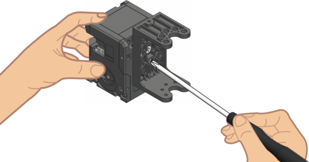
Check DYNAMIXEL ID
Check DYNAMIXEL Horn Position
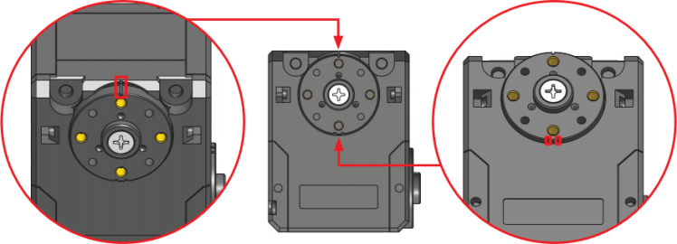
CAUTION
- The marking on the housing should match to the horn marking when properly centered.
- In order to align the horn to the center, use PH 1 screw driver to rotate the horn screw to clockwise. Be aware of rotating the screw to counter clockwise as it will release the screw.
Rivet Assembly
6mm Rivet
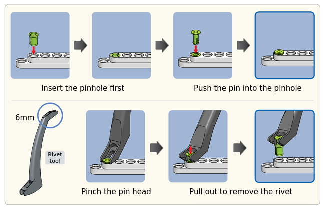
CAUTION : When reusing rivets, the pin hole must be inserted first. Used rivet will not be separated into pin and pinhole.
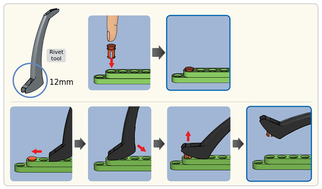
12mm Rivet
Cable Assemlby
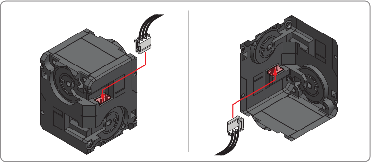
Connector
Both connectors are linked to supply power and communication to the module. Please use any connector for easier assembly.
Wiring through Idler Cap
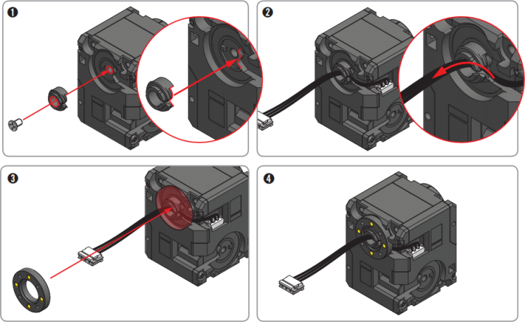
NOTE :
Through hole wiring method helps to increase the durability of cable and to simplify cable assembly.
It is not a mandatory and it may require more time to replace the cable afterward.
Quick Start
App Installation
- ROBOTIS ENGINEER KIT supports R+Task 3.0.
- R+ Task 3.0 is an integrated software tool that combines R+ Task 2.0 and R+ Motion 2.0.
- Easily program your robot with the R+ task tool.
- Make any motion easily with the integrated motion tool.
![]()
- Download R+ Task 3.0 for Windows (PC).
- Download R+ Task 3.0 for Mac OS (PC).
- Download R+ Task 3.0 For Android Device (Google Play).
- Download R+ Task 3.0 For Apple Device (App Store)
![]()
NOTE: R+Task 3.0 does not support Python Code Download on smart devices. Please download your code using R+Task 3.0 on a PC.
Download Examples
- CM-550 controller is initially programmed with Kit1 example.
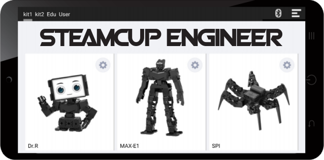
- The
Complete ExampleincludesDr.R,MAX-E1,SPIexamples.
| Example | Task Files | Motion Files |
|---|---|---|
| Complete Example | 01_ENG1_TOTAL_EN.tsk3 | 01_ENG1_TOTAL_EN.mtn3 |
| Dr.R | 02_ENG1_DR_R_EN.tsk3 | 02_ENG1_DR_R_EN.mtn3 |
| MAX-E1 | 03_ENG1_MAX_E1_EN.tsk3 | 03_ENG1_MAX_E1_EN.mtn3 |
| SPI | 04_ENG1_SPI_EN.tsk3 | 04_ENG1_SPI_EN.mtn3 |
Download from PC
- How to Connect CM-550 Controller to PC
- How to Download Task Example via PC
- How to Download Motion Example via PC
Download from Smart Device
NOTE : Connect CM-550 with your smart device via bluetooth. See Pairing Bluetooth.
- How to Connect CM-550 Controller to Mobile
- How to Download Task Example via Mobile
- How to Download Motion Example via Mobile
Run Examples
Launch the R+ ENGINEER app and select the assembled robot example to operate the robot.
CAUTION : Selecting wrong example may result in malfunction of the robot.
Select the menu button on the top right corner of the app for app configuration.
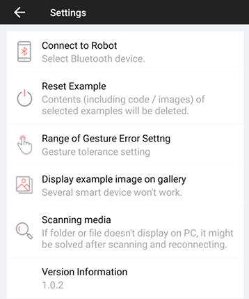
Connect to Robot : Select Bluetooth device to connect.
Reset Example : Reset selected examples.
Range of Gesture Error Setting : Configure the error margin of the gesture.
Display Example Image on Gallery : Show example images in the smart device gallery.
Scanning Media : Refresh the smart device files/folders when not detected from PC.
Version Information : Display the current app version.
Pairing Bluetooth
-
Turn on the CM-550 controller with power switch.
-
Press the
MODEbutton until green light flashes.
NOTE : The
MODEbutton flashes in green when the controller is ready to run the task program. -
Press the
STARTbutton.
NOTE : While the
MODEbutton flashes in green, pressingSTARTbutton will run the task program. -
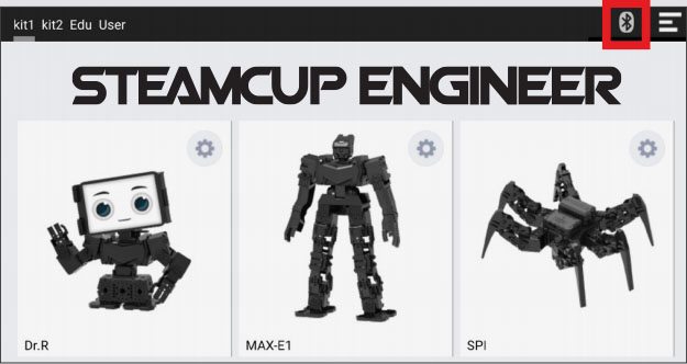
Launch the
ROBOTIS ENGINEERapp from the smart device and press the Bluetooth icon.
-
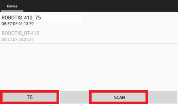
Find the BLE MAC address of the CM-550 controller.
-
Enter the last two characters of BLE MAC address in the left box and press
Searchicon.
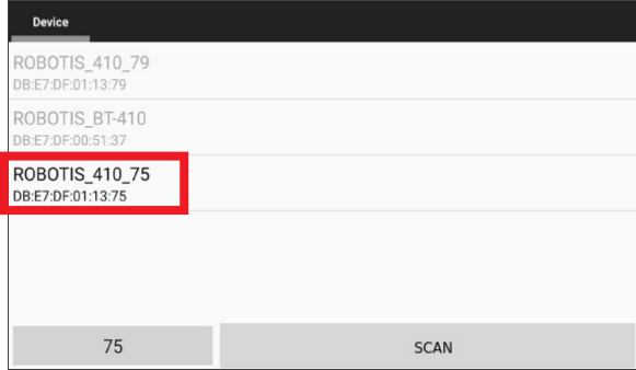
-
Select the BLE MAC address from the search list.
Dr.R
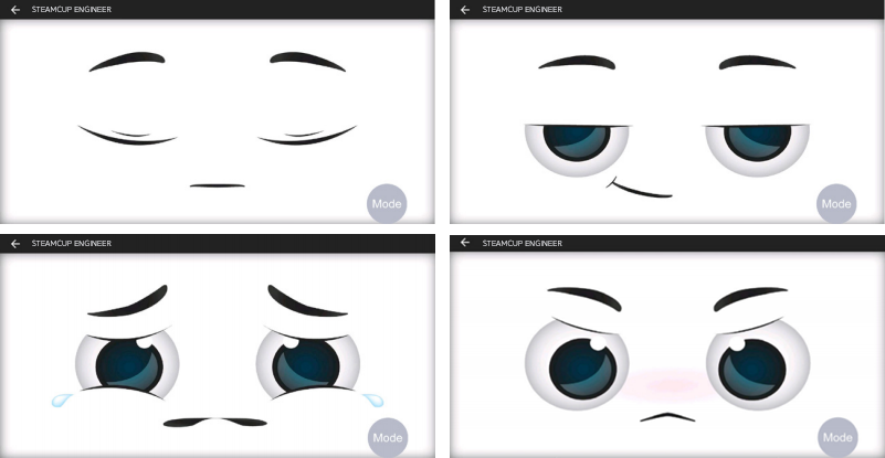
Emotion
Selecting Dr.R example from R+ Engineer app will display robot face on the screen. Touch robot or trigger events to change the emotion of the robot with facial expressions, motions and speeches.
Select Mode
Press the Mode button to display supported modes and options.
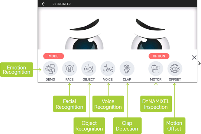
Mode Menu
| Icon | Mode Description |
|---|---|
| DEMO : Emotion Recognition This default demo mode expresses Dr.R’s emotion on the smart device screen. Touch the robot or smart device will affect to Dr.R’s emotion and behavior. |
|
| FACE : Face Recognition The robot detects and tracks the face with the camera of the smart device. AR technology will overlay an image on the detected face. |
|
| OBJECT : Object Recognition The robot recognizes machine learned objects with the smart device camera. Dr.R can distinguish 12 different objects including banana, pen, car key, wallet, paper money etc. |
|
| VOICE : Voice Recognition The robot recognizes registered voice commands. Commands such as mode change, option menu execution, and termination are registered. |
|
| CLAP : Clap Detection The robot detects clapping sound with the controller microphone. Dr.R will clap as many as perceived claps. |
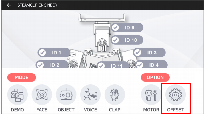
Option Menu
| Icon | Option Description |
|---|---|
| MOTOR : DYNAMIXEL Inspection This feature inspects each joint of the robot. |
|
| OFFSET : Motion Offset This feature calibrates the offset position of each joint for proper motions. |
NOTE : The Option Menu is available in all examples. Please refer to Setting Up the Robot for more details.
MAX-E1
Remote Controller Screen
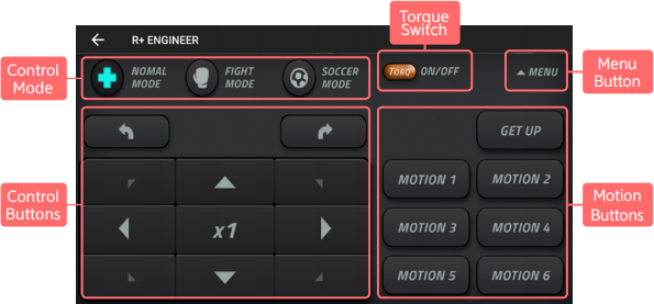
Control Modes : Select Normal / Fight / Soccer mode for MAX-E1.
Control Buttons : Control robot’s motion speed and moving directions.
Motion Buttons : Registered motions of MAX-E1 can be played.
Torque Button : DYNAMIXEL Torque On/Off switch.
Menu Button : Open additional menu for MAX-E1.
Mode Menu
| Icon | Mode Description |
|---|---|
| REMOTE : Use smart device as a remote controller. | |
| GESTURE : Use registered gestures in the smart device to control the robot. | |
| CLAP : The robot detects clapping sound and MAX-E1 will clap as many as perceived claps. |
SPI
Remote Controller Screen
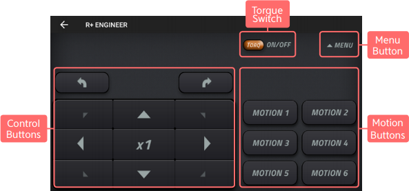
Control Buttons : Control robot’s motion speed and moving directions.
Motion Buttons : Registered motions of SPI can be played.
Torque Button : DYNAMIXEL Torque On/Off switch.
Menu Button : Open additional menu for SPI.
Mode Menu
| Icon | Mode Description |
|---|---|
| REMOTE : Use smart device as a remote controller. | |
| MUSIC : SPI and smart device play music together. | |
| CLAP : The robot detects clapping sound and SPI will clap as many as perceived claps. |
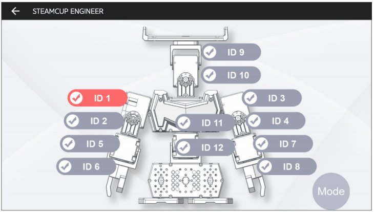
Setting Up the Robot
Check DYNAMIXEL Assembly
This function checks DYNAMIXEL ID and status of the ROBOTIS ENGINEER Kit.
-
Launch the robot example from the main screen, and select
MOTORfrom the option menu.
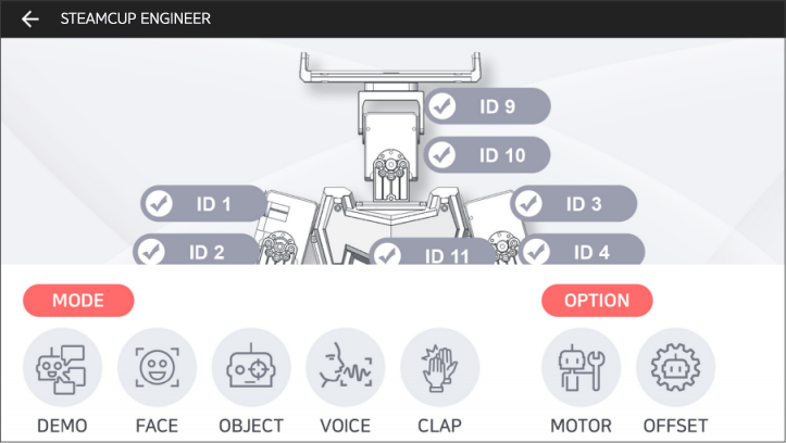
-
Select the joint ID from the screen. Check if the selected joint flinches while LED is turned on.
DYNAMIXEL Offset
This function is used to adjust the pose of robot by calibrating offset values of DYNAMIXEL used in the ROBOTIS ENGINEERING KIT. Configured offset value will be saved in each DYNAMIXEL’s.
Please perform offset adjustment with a thorough understanding as it may cause unstable motions or hardware damages when improperly configured.
-
Launch the robot example from the main screen, and select
OFFSETfrom the option menu.
-
Select the joint ID to adjust offset from the screen and adjust menu will appear.
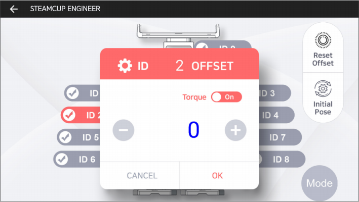
+ / -: Increase / Decrease the offset value.Torque On / Off: Toggle the torque of the selected joint.OK / CANCEL: Save / Cancel the changes in offset value.
-
Select
OKto save the offset value. The confirmation message will appear.
SelectOKonce again to save the offset value to robot.
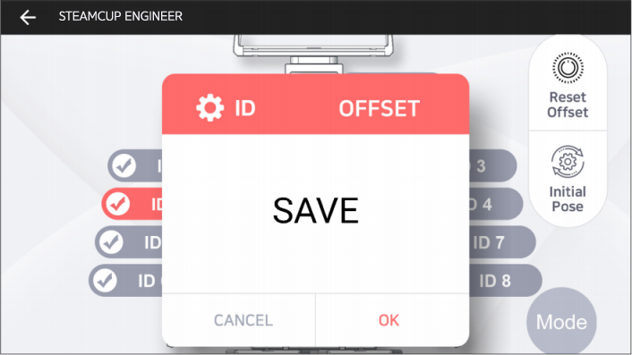
-
Below buttons will reset or reload offset values of each joint.
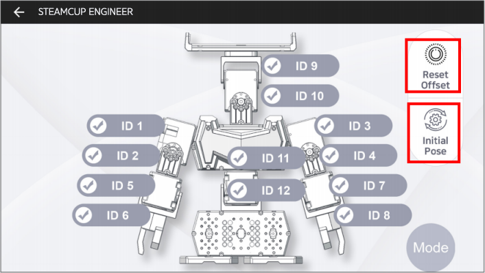
Reset Offset: When selected, the confirmation window will appear. Select [OK] to reset the offset value of all joint.Initial Pose: This button will reload the saved offset value. Incorrectly configured offset may be recovered with this button.
Tutorials
[Machine Learning] Object Detection
Get started to learn a machine learning with ROBOTIS ENGINNER and Tensor Flow developed by Google Brain.
Tensor Flow is a machine learning application to ease the process of acquiring data and training models.
Once you finish this instruction, you will understand how to utilize the object detection which is one of the part of a machine learning.
Explore following simple steps and train your robot to recognize your custom objects.
- Use a smart device with a camera to utilize the object detection.
- Install R+ ENGINEER in the smart device.
Windows
Anaconda is the easiest way to perform a machine learning and a large-scale data processing on Linux, Windows, and Mac OS X. To utilize an object detection with ROBOTIS ENGINEER, install Anaconda3 4.2.0 for Windows (64/32 bit) on your PC to build your own image classifier using Tensor Flow.
Upgrade pip Packages
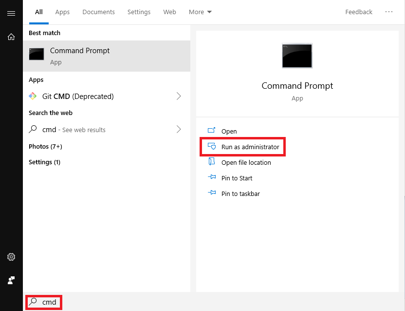
- Open a Command Prompt as an administrator.
- Press
WIN+Son your keyboard to open a Windows search box. - Type CMD into the Windows search box and click the resulting “Command Prompt” as an administrator.
- Press
-
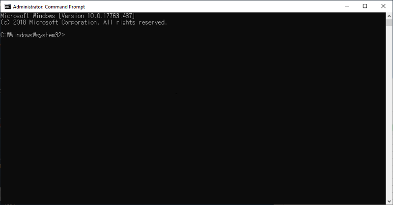
Command Prompt will be popped if you get access to CMD in the administrator mode.
-
Copy the following command and paste it into Command Prompt.
python -m pip install --upgrade pip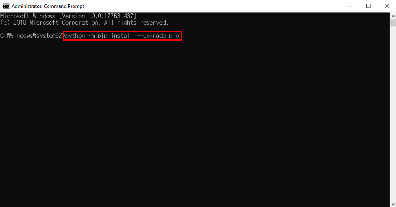
-
As shown in the picture below, new pip package will be installed.
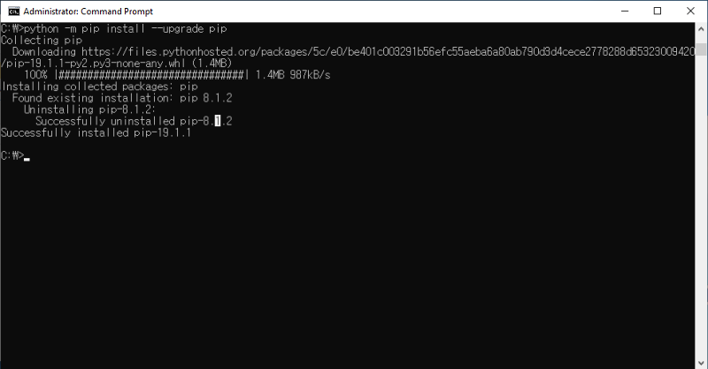
If there are issues with pip upgrade, check download path if it was proper location. As software is installed on
C Driveby default, move a folder of Anaconda3 installed intoC Drivethen upgrade pip package.
Create Folder
-
Create Folder named
!R+Smart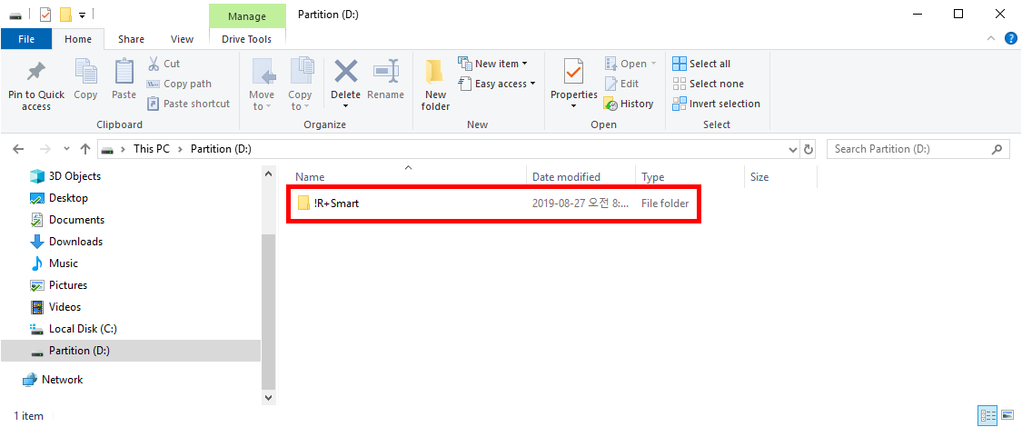
- You can create the folder in any location on your PC, but make sure a path in Command Prompt must coincide with the location of its folder properly.
- You can change a folder name, but make sure the name in Command Prompt must coincide with the actual folder name.
- In this instruction, the folder name is
!R+Smart, and the path isC Drive.
-
Change your path in Command Prompt into
D Drivewhere!R+Smartfolder exists as your current location in Command Prompt isC Drive.d: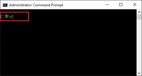
-
Copy the following command and paste it in Commad Prompt to move into
!R+SmartfromD drive.cd !R+Smart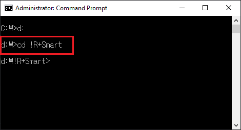
Create Virtual Environment
-
Copy the following command and paste it in Command Prompt to create a virtual environment for your project.
conda create -n tensorflow python=3.5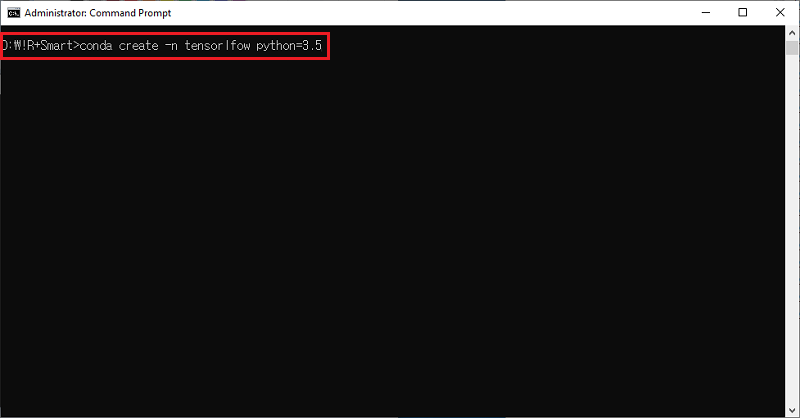
-
It will ask you if you want to proceed to the next step. Press
y, and then pressEnterkey to install the Python version and new packages.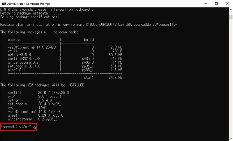
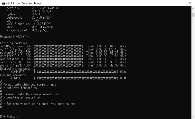
-
As shown in the picture, you can see all the packages are successfully installed.
Install Tensor Flow
Tensor Flow installation can be done in two simple steps.
-
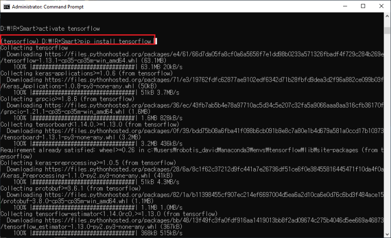
Copy the following command and paste it in Command Prompt to activate newly created virtual environment of Tensor Flow.
activate tensorflow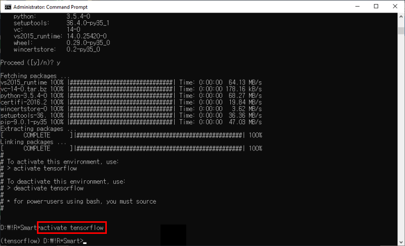
-
Lastly, Copy the following command and paste it in Command Prompt to install Tensor Flow.
pip install tensorflow==1.13.1WARNING: Be sure to install tensorflow 1.13.1. Otherwise, it may cause unexpected errors.
Create a file and a folder
-
Go on the associated link to download a
retrain.pyfile. -
Move the downloaded file
retrain.pyin!R+Smartfolder. Create aphotosfolder in!R+Smartto add images for an object detection.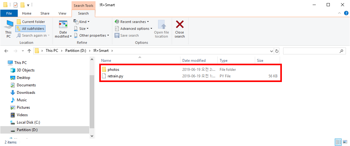
-
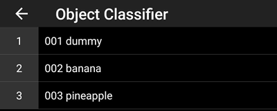
Create subfolders named
001 dummy,002 bananaand003 pineappleor something like that, which contains images matching a detected object characteristic for an object detection.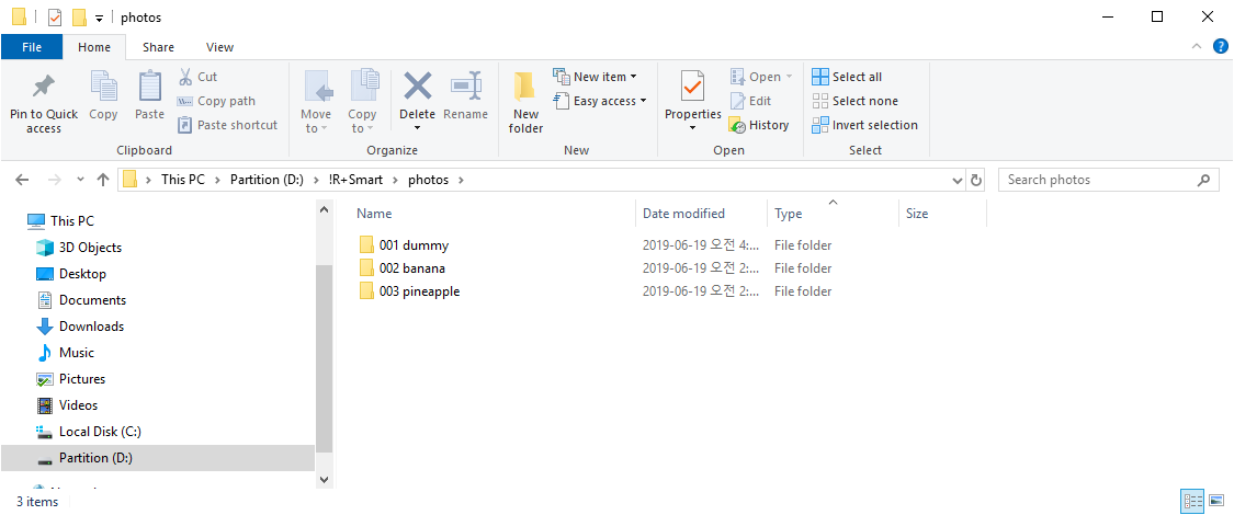
NOTE :
- To reduce errors of recognizing objects,
001 dummyfolder will be useful to scan unspecified objects. - Train your ROBOTIS ENGINEER with sufficient images. The more it is, the better performance it is. (Collecting 100 images will be enough for recognizing objectes)
- To organize folders in order, specify them with a number
001,002,etc..
Train models
-
Copy the following command and paste it in Command Prompt to train models of objects.
python retrain.py --bottleneck_dir=./bottlenecks --model_dir=./inception --output_graph=./Smart_OC.pb --output_labels=./Smart_OC.txt --image_dir ./photos --architecture mobilenet_1.0_224 --how_many_training_steps 1000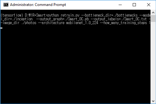
In the command line, the option
how_many_training_stepsis the count of steps of training models. The enough steps for training models are 1000 times. -
After completion of training,
Smart_OC.txtandSmart_OC.pbfiles will be created in the!R+Smartfolder.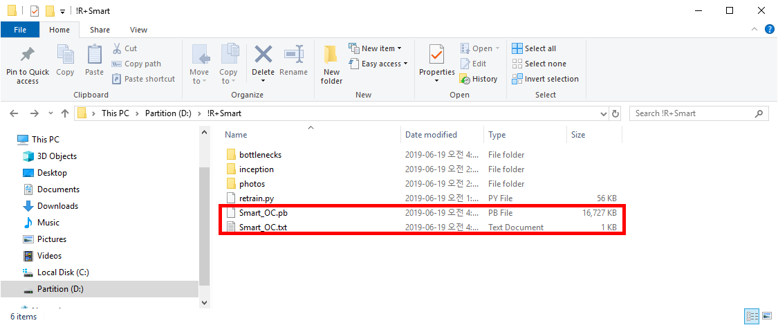
Apply training file to your prject
-
Connect your smart device in which
R+ ENGINEERapp installed to your PC. -
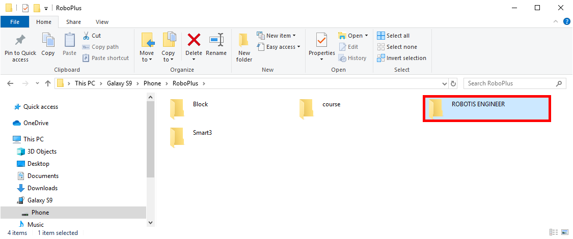
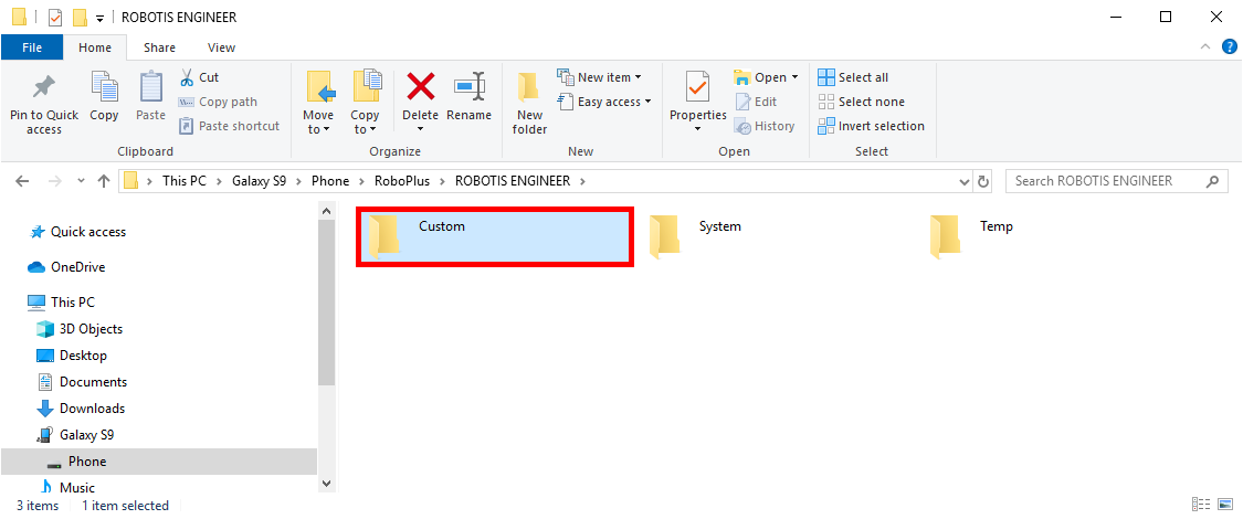
Enter
RoboPlus>ROBOTIS ENGINEER>CUSTOMof your device folder.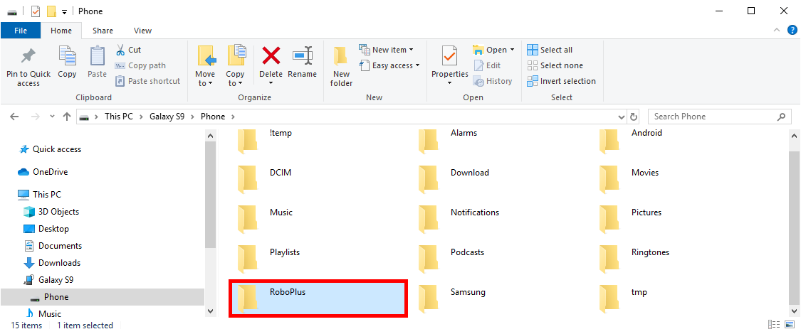
-
Create a folder named
Project 1in theCUSTOMfolder.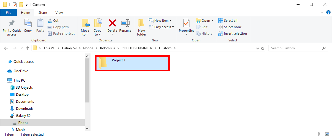
NOTE : If there is your own project, you can skip 3rd step of this instruction.
-
Create a
Dbfolder to store training files.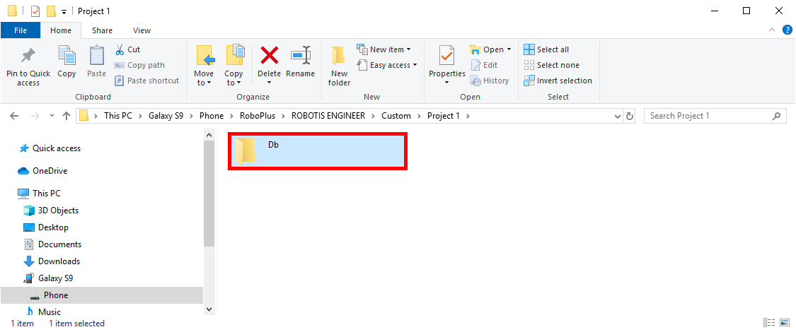
-
Copy
Smart_OC.txtandSmart_OC.pbfiles from!R+Smartand then paste them into theDbfolder.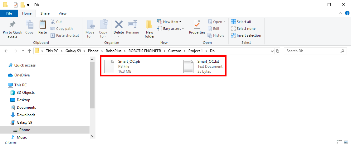
-
Disconnect the smart device from the PC, and then launch the
ROBOTIS ENGINEERapp on your smart device. -
Click
Usertab.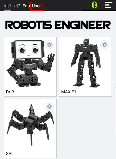
-
Click a configuration icon of a folder
Project 1.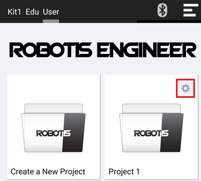
-
Select
Object ClassifieratVisionsection.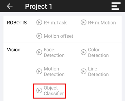
-
To test object detection, select your custom object in the list.
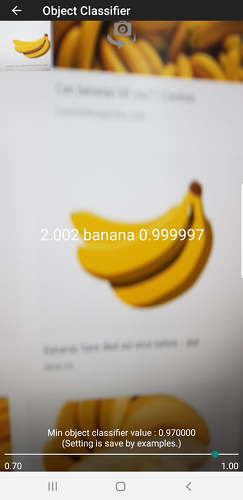
-
Detect objects in real time.
NOTE : It is not possible to add new object datas to Smart_OC.txt and Smart_OC.pb, which have been already configured. To add new data into them, please add a new object image to the subfolders created in !R+Smart .
Study Materials
Apply for Study Materials
Additional course materials can be downloaded from below link.
Assembly Manual Download
| Model | Download |
|---|---|
| Dr.R | ROBOTIS_ENGINEER_KIT1_DrR_EN_ver2113.pdf |
| MAX-E1 | ROBOTIS_ENGINEER_KIT1_MAX-E1_EN_ver2113.pdf |
| SPI | ROBOTIS_ENGINEER_KIT1_SPI_EN_ver2113.pdf |
| Educ (Additional Examples) | ROBOTIS_ENGINEER_KIT1_Educ_EN_ver2113.pdf |
| Quadruped Robot (Additional Examples) | ROBOTIS_ENGINEER_KIT1_QuadrupedRobot_EN_ver2113.pdf |
| Gimbal Mini (Additional Examples) | ROBOTIS_ENGINEER_KIT1_GimbalMini_EN_ver2113.pdf |
| Gimbal (Additional Examples) | ROBOTIS_ENGINEER_KIT1_Gimbal_EN_ver2113.pdf |
| Excavating Manipulator (Additional Examples) | ROBOTIS_ENGINEER_KIT1_ExcavatingManipulator_EN_ver2113.pdf |
References
BLE Signal Setting
The Bluetooth communication could be unstable if the signal strength of BLE slave module in the CM-550 is weak or interfered.
The BLE signal strength can be adjusted by R+ Manager 2.0 in this case.
Please refer to the method to adjust CM-550 BLE signal strength for various situations.
| My CM-550 | Other CM-550 | BLE Signal Strength |
|---|---|---|
| Unstable Link | Stable Link | Increase |
| Unstable Link | Unstable Link | Increase |
| Stable Link | Unstable Link | Decrease |
| Stable Link | Stable Link | No Change |
- If communication is unstable when using one CM-550 controller in the room, the signal strength might be weak. Increase the BLE signal strength.
- If communication is unstable when using multiple CM-550 controllers in the room, BLE signals could interrupt each other. Increase the BLE signal strength of the unstable CM-550 or decrease the BLE signal strength of other stable CM-550.
- If all CM-550 in the room are stable, Maintain the BLE signal strength.
NOTE : The BLE signal strength and noise may differ by environment and the number of devices nearby.
-
Turn off the BT-410 master or BT-410 Dongle that is paired to CM-550 BLE.
(BLE signal strength cannot be configured while CM-550 BLE is connected to the paired device) - Connect the USB cable from PC to CM-550 (5V USB will automatically turn on the controller even if the power switch is off).
- Wait until the
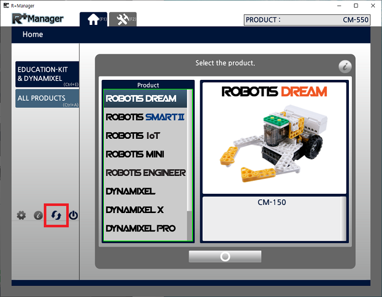
MODEbutton of CM-550 flickers every second. - Run R+ Manager 2.0.
-
Click the
Check for Updatesbutton to install the latest updates.
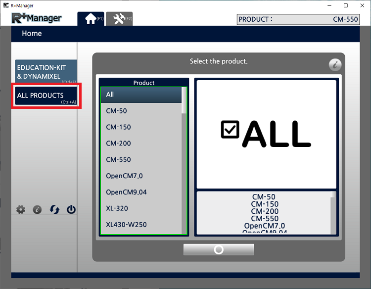
-
Go to
ALL PRODUCTStab or use shortcut key(Ctrl+A).
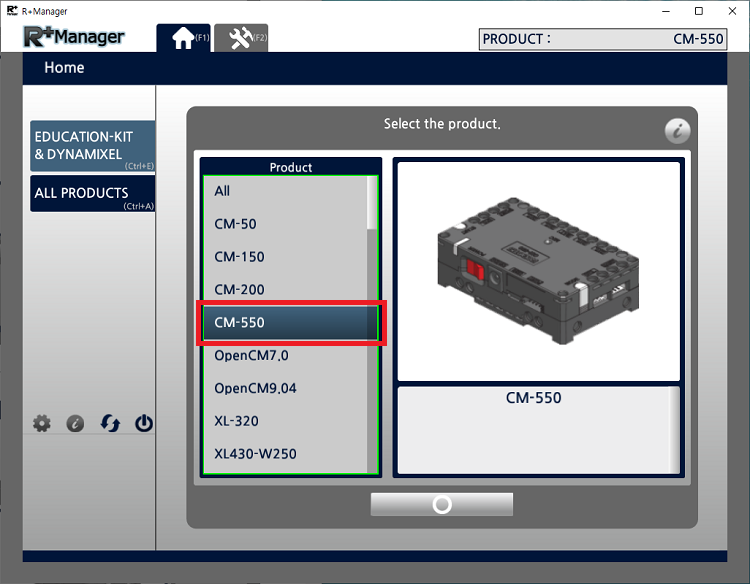
-
Select
CM-550from the product list.
-
Click
Update & Testbutton.
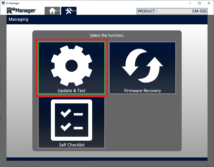
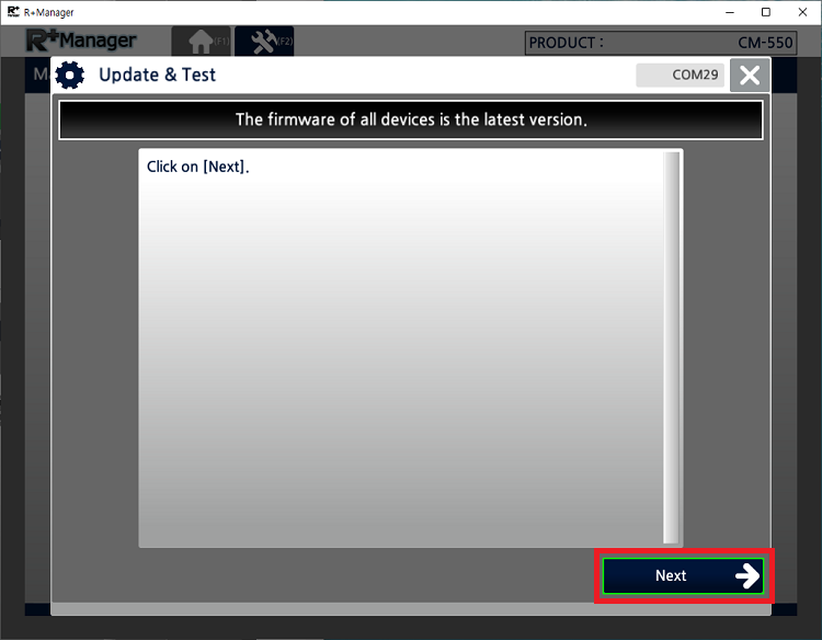
-
Click
Nextbutton.

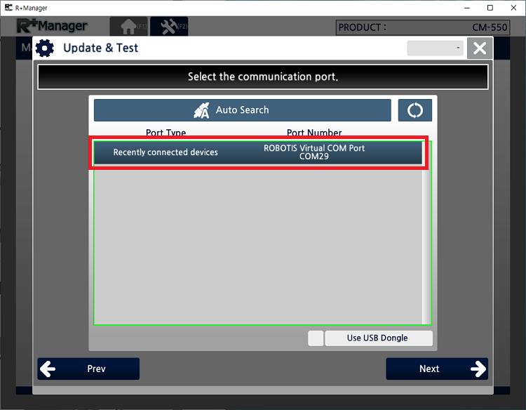
-
Select the port where the controller is connected to.
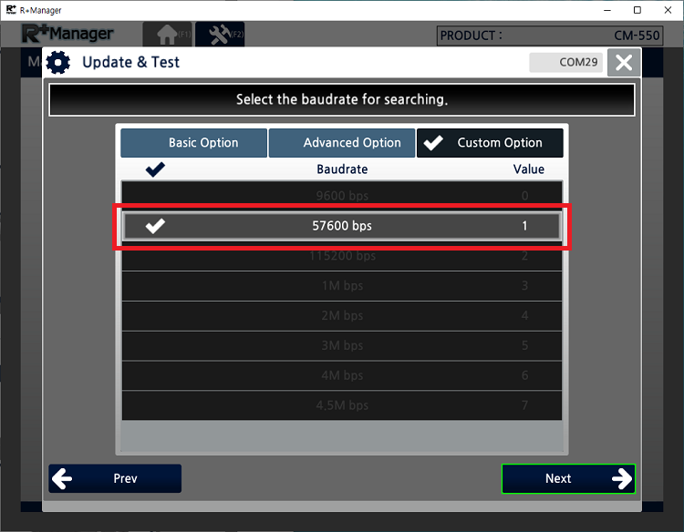
-
Confirm the Baudrate (The default baudrate is fixed to 57600 bps).
-
Once CM-550 controller is detected, click
Next.
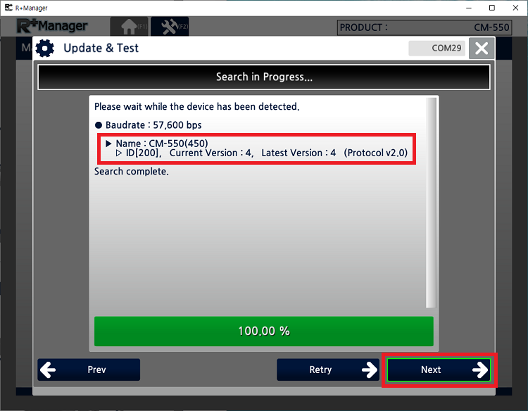
-
If the controller has the latest firmware, click
Next, or else follow the update instruction on the screen to download the latest firmware.
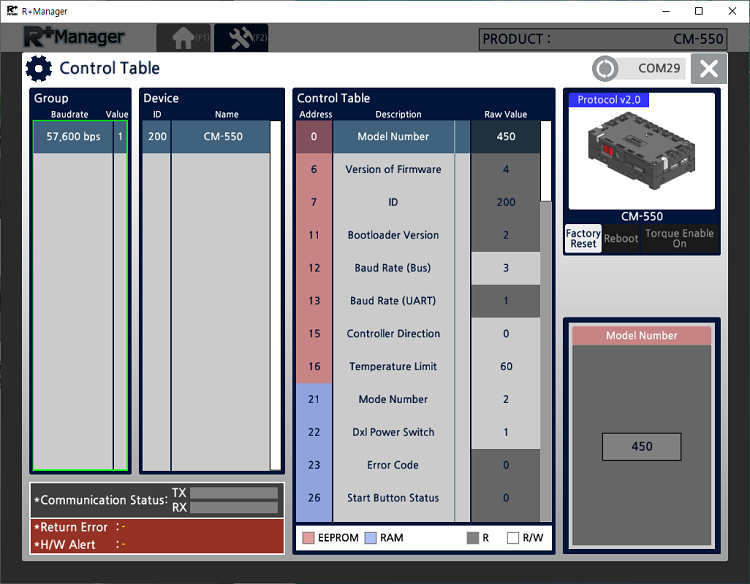
-
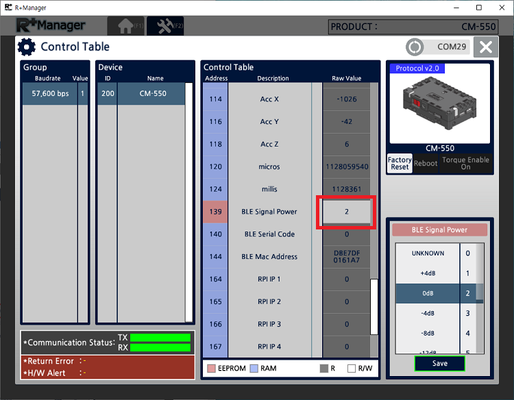
Upon the successful connection, below control table will appear on the screen.
-
Scroll down until to find
BLE Signal Powerin the address139.
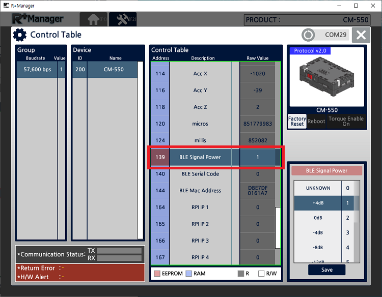
-
Select the
BLE Signal Poweron the right section of the control table and clickSavebutton.
The bigger value will increase the signal strength.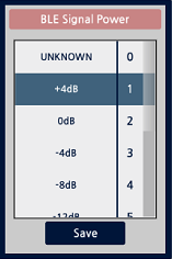
If the value of
BLE Signal Poweris marked onUNKNOWN(0), please go back to step 1 and check if BT-410 Master or BT-410 Dongle module is turned off. - Confirm the changed
BLE Signal Powervalue.
Self Checklist
- Why the robot does not turn on?
Please check the battery level and connection.
- How can I check the battery level?
Please refer to Battery Level Check section.
- I keep hearing the alarm from the robot.
If the battery level is too low, battery warning alarm sounds. Please refer to Charging Battery section.
- The robot motion seems awkward.
The robot may not assembled properly. Please check the robot assembly and Check DYNAMIXEL Assembly section.
- The robot turns on with the adapter, but not with the battery.
Please check the Fuse on the bottom of CM-550 controller. Please refer to Fuse Replacement section.
How to Reset
If the robot needs to be reset to it’s factory condition due to a malfunction, you may need to re-download the provided basic examples (.tsk3 and .mtn3) to the CM-550 to reset the robot. To do it, go to the Download Examples and see Download from PC.
Charging Battery
CAUTION
- The provided battery must be charged with the provided charger(LBC-10) in the kit.
- Please power the charger before connecting the battery.
- Please fully charge the battery prior to first use.
-
Get the rechargeable battery in the kit.
-
Connect the battery to the charger as shown below.
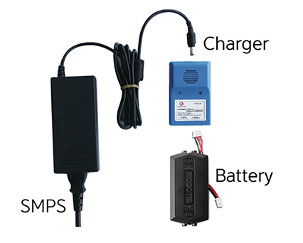
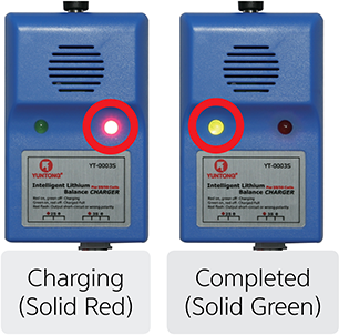
-
When fully charged, the LED will emit a solid green light.
-
The robot and controller can also be powered by the SMPS without the battery.
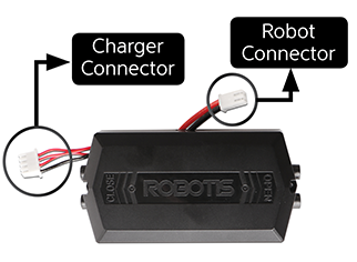
-
The battery has separate connectors for the charger and the robot. Please disconnect the
Robot Connectorfrom the robot when charging the battery.
Battery Level Check
Current battery life can be verified by the color of the LED located on the CM-550.
- Blue : 70% ~ 100%
- Green : 30% ~ 70%
- Red : Under 30% (Low voltage alarm)
NOTE : The Power LED will blink when Bluetooth connection is disconnected.
CAUTION : Please disconnect the battery from the charger when charging is completed. Please do not charge the battery while operating the robot.
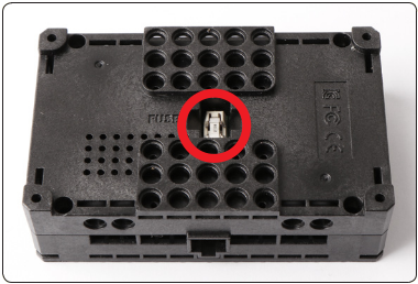
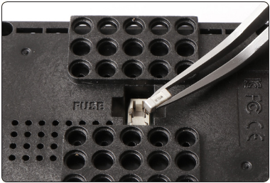
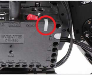
Fuse Replacement
The fuse in CM-550 protects hardware from unexpected excessive current.
If CM-550 can be turned on with the SMPS, but not with the battery, please check the fuse and replace it if necessary.
DANGER : Disconnect any power sources(SMPS, battery, USB) from CM-550 before replacing the fuse.
Disconnect power source from CM-550 and replace the fuse on the bottom of CM-550.