
Introduction
CM-200
- Can connect and control SMART device (reduction motors, servo motors, touch sensors, IR sensor, LED mobules, etc)
- Recover controller firmware with RoboPlus Manager (v1.0.30.0 or higher) or RoboPlus Manager 2.0
- Write a task code and control device with RoboPlus Task (v1.1.1.0 or higher) or R+ Task 2.0 and R+ Task 3.0
- The CM-200 supports RoboPlus Motion
Specifications
| Item | Description |
|---|---|
| Weight | 25g |
| CPU | STM32F103C8 |
| Size | 54mm x 42mm x 18mm |
| Voltage Supply | Range : 4.8V ~ 8.4V Recommended : 6.0 ~ 7.4V (AA Battery x 4 or Li-ion Battery x 2) |
| Current Consumption | Standby(80mA) Running(150mA) Max(300mA) |
| Operation Temperature | -5°C ~ 70°C |
| Internal I/O components | IR sensor(measure distance) x 3 Mic(Sound sensor) x 1 Buzzer x 1 |
| External I/O components | 4-pin comunication (wireless control & download) x 1 Motor potrs (for reduction motor) x 2 Multi-usage port(sensor and outputs) x 8 |
![]()
DANGER
(Ignoring these warnings may cause serious injury or death)
- Never place items containing water, flammables/open flames, or solvents near the product.
- Never place fingers, arms, toes, and other body parts near product during operation.
- Cease operation and remove power from the product if the product begins to emit strange odors, noises, or smoke.
- Keep product out of reach of children.
- Check input polarity before installing or energizing wiring or cables.
![]()
CAUTION
(Ignoring these warnings may cause mild injury or damage to the product)
- Always comply with the product’s offical operating environment specifications including input voltage, current, and operating temperature.
- Do not insert blades or other sharp objects during product operation.
![]()
ATTENTION
(Ignoring these warnings may cause minor injury or damage to the product)
- Do not disassemble or modify the product.
- Do not drop the product or apply strong impacts.
- Do not connect or disconnect DYNAMIXEL cables while power is being supplied.
Control Table
Control Table consists of data regarding the current status and operation of controller. The user can control controller by changing data of Control Table via Instruction packet.
-
EEPROM and RAM
Data in RAM area is reset to initial values whenever the power is turned on while data in EEPROM area is kept once values are set even if the power is turned off. -
Address
Represents the location of data. To read from or write data to the control table the user should assign the correct address in the Instruction packet. -
Access
Controller has two kinds of data: Read-only data, used mainly for sensing, and read-and-write data used for driving. -
Initial Value
In case of data in the EEPROM Area, the initial values on the right side of the below Control Table are the factory default settings.
In case of data in the RAM Area, the initial values on the right side of the following control table are the ones when the power is turned on. -
Size
The Size of data varies from 1 ~ 4 bytes depend on their usage. Please check the size of data when updating the data with an Instruction Packet.
EEPROM Area
| Address | Size | Name | Description | Access | Init Value |
|---|---|---|---|---|---|
| 0 | 2 | Model Number | Model Number | R | 400 |
| 6 | 1 | Firmware Version | Firmware Version | R | - |
| 7 | 1 | ID | Controller ID | RW | 200 |
| 8 | 1 | Baud Rate | Communication Baud Rate | R | 1 |
| 9 | 1 | Return Delay Time | Response Delay Time | RW | 0 |
| 10 | 1 | Status Return Level | Select Types of Status Return | RW | 2 |
RAM Area
| Address | Size | Name | Description | Access | Init Value |
|---|---|---|---|---|---|
| 21 | 1 | Mode Number | Operation Mode | RW | - |
| 25 | 1 | Press Counter | Counts Start Button Press | R | - |
| 26 | 1 | Button Status | Start Button Status | R | 0 |
| 30 | 2 | My Zigbee ID | Local Zigbee ID | R | - |
| 32 | 2 | Your Zigbee ID | Remote Zigbee ID | RW | - |
| 36 | 1 | IR Communication Channel | IR Receiver Channel Number | RW | 1 |
| 66 | 2 | Motion Play Page | Motion Play Page Number | RW | 0 |
| 68 | 1 | Motion Play Status | Motion Play Status | R | - |
| 73 | 1 | 128ms Timer Value | 128ms Timer Counter | RW | 0 |
| 74 | 2 | 1ms Timer Value | 1ms Timer Counter | RW | 0 |
| 76 | 1 | Power Save Timer Value | Power Save Timer Counter | RW | 0 |
| 77 | 1 | Random Number | Creating Random Number | RW | - |
| 79 | 1 | AUX LED(Red) | AUX LED(Red) Status | RW | 0 |
| 84 | 1 | Buzzer Index | Buzzer Melody Frequency | RW | 0 |
| 85 | 1 | Buzzer Time | Buzzer Play Time | RW | 0 |
| 86 | 1 | Sound Detected Count | Final Count for Detected Sound | R | 0 |
| 87 | 1 | Sound Detecting Count | Current Count for Detected Sound | R | 0 |
| 88 | 2 | Low Battrey Sound Enable | Enable Low Battery Warning | RW | 0 |
| 91 | 2 | Internal Right IR Sensor Value | Sensor Value of Right IR | R | - |
| 93 | 2 | Internal Left IR Sensor Value | Sensor Value of Left IR | R | - |
| 95 | 2 | Internal Center IR Sensor Value | Sensor Value of Center IR | R | - |
| 97 | 1 | Input Power Voltage (unit : 0.1V) | Measures Input Voltage | R | - |
| 128 | 1 | Port 3 Servo Mode | Servo Motor on Port 3 | RW | - |
| 129 | 1 | Port 4 Servo Mode | Servo Motor on Port 4 | RW | - |
| 136 | 2 | Port 3 Motor Speed | Speed of the Motor on Port 3 | RW | - |
| 138 | 2 | Port 4 Motor Speed | Speed of the Motor on Port 4 | RW | - |
| 152 | 2 | Port 1 Motor Speed | Speed of the Motor on Port 1 | RW | - |
| 154 | 2 | Port 2 Motor Speed | Speed of the Motor on Port 2 | RW | - |
| 156 | 2 | Port 3 Servo Position | Position of the Motor on Port 3 | RW | - |
| 158 | 2 | Port 4 Servo Position | Position of the Motor on Port 4 | RW | - |
| 172 | 2 | Port 3 IR Sensor Value | IR Sensor Value on Port 3 | R | - |
| 174 | 2 | Port 4 IR Sensor Value | IR Sensor Value on Port 4 | R | - |
| 204 | 1 | Port 3 Touch Sensor Value | Touch Sensor Value on Port 3 | R | - |
| 205 | 1 | Port 4 Touch Sensor Value c | Touch Sensor Value on Port 4 | R | - |
| 212 | 1 | Port 3 LED Module Value | Port 3 LED Module Control Value | RW | 0 |
| 213 | 1 | Port 4 LED Module Value | Port 4 LED Module Control Value | RW | 0 |
| 220 | 2 | Port 3 User Device Value | User Device Value on Port 3 | RW | 0 |
| 222 | 2 | Port 4 User Device Value | User Device Value on Port 4 | RW | 0 |
| 236 | 1 | Port 3 Temperature Sensor Value | Temperature Sensor Value on Port 3 | R | - |
| 237 | 1 | Port 4 Temperature Sensor Value | Temperature Sensor Value on Port 4 | R | - |
| 244 | 1 | Port 3 Ultrasonic Sensor Value | Ultrasonic Sensor Value on Port 3 | R | - |
| 245 | 1 | Port 4 Ultrasonic Sensor Value | Ultrasonic Sensor Value on Port 4 | R | - |
| 252 | 1 | Port 3 Magnetic Sensor Value | Magnetic Sensor Value on Port 3 | R | - |
| 253 | 1 | Port 4 Magnetic Sensor Value | Magnetic Sensor Value on Port 4 | R | - |
| 260 | 1 | Port 3 Motion Sensor Value | Motion Sensor Value on Port 3 | R | - |
| 261 | 1 | Port 4 Motion Sensor Value | Motion Sensor Value on Port 4 | R | - |
| 268 | 1 | Port 3 Color Sensor Value | Color Sensor Value on Port 3 | R | - |
| 269 | 1 | Port 4 Color Sensor Value | Color Sensor Value on Port 4 | R | - |
| 276 | 1 | Port 3 Hydro-Thermo Sensor Humidity Value | Humidity Value on Port 3 | R | - |
| 277 | 1 | Port 4 Hydro-Thermo Sensor Humidity Value | Humidity Value on Port 4 | R | - |
| 284 | 1 | Port 3 Hydro-Thermo Sensor Temperature Value | Temperature Value on Port 3 | R | - |
| 285 | 1 | Port 4 Hydro-Thermo Sensor Temperature Value | Temperature Value on Port 4 | R | - |
| 292 | 2 | Port 3 Brightness Sensor Value | Brightness Sensor Value on Port 3 | R | - |
| 294 | 2 | Port 4 Brightness Sensor Value | Brightness Sensor Value on Port 4 | R | - |
NOTE : Some Addresses of the Control Table can be tested with R+ Manager 2.0.
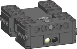
Layout
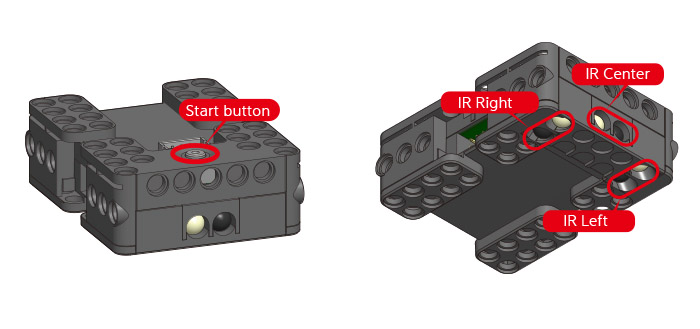
- Start button: After a short press the LED will turn on and the loaded program runs
- IR sensors : measure and program each of the integrated 3 IR sensors
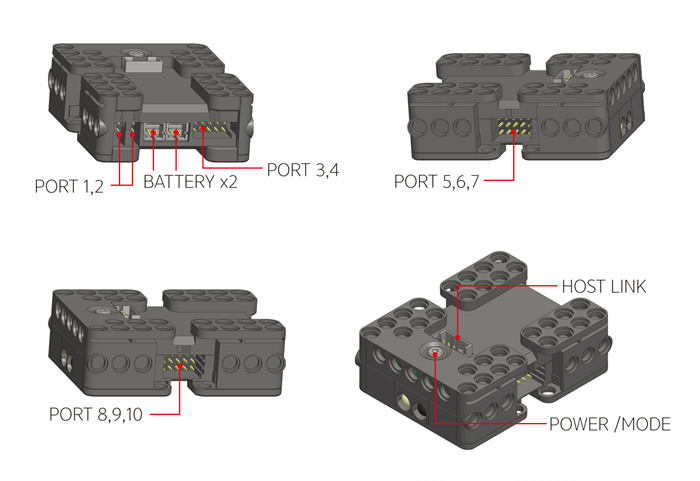
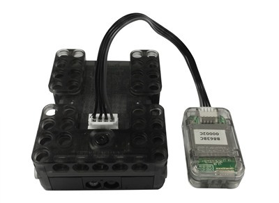
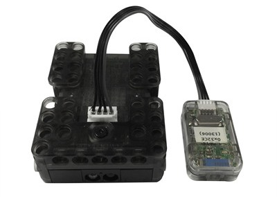
- Top 4-pin port : located next to the Start button connect an IR receiver, USB downloader (LN-101), ZIG-110A or BT210A
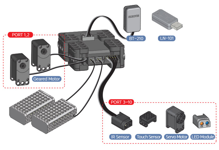
- Port 1 ~ 2 : shown as “I” and “II” connect reduction motors
- Port 3 ~ 4 : shown as “III” and “IIII” connect IR sensors, touch sensors, servo motors and LED modules.
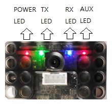
- POWER LED (red): LED turns on when powered on
- TX LED (green): Data transmission LED from controller to external device (via 4-pin port)
- RX LED (blue): Data reception LED from external to controller (via 4-pin port)
- AUX LED (red): user-controlled on/off function
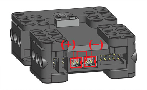
Connecting Power
- Power for the CM-200 is supplied by 2 ABB-030 battery or a single LB-041 Li-ion battery (LB-040 is discontinued).
- Operating voltage range: 4.8-8.4V (6.0-7.4V recommended)
- Power polarity pins are shown in the diagram below
How to Operate
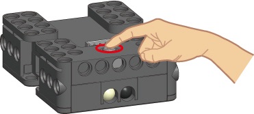
- Press the Start button the LED turns on and the controller runs one downloaded program
- Press the Start button to turn on then press the Start N times. The controller is can run a specific parts of a program given said N number of presses.
- Hold the Start button for more than 1 second and it will emit 2 beep sounds, LED turns on, and the controller is under management mode (downloading not possible in this mode).
- Hold the Start button for more than 5 seconds and it will emit 3 beep sounds. The controller is in firmware recovery mode
- The controller automatic turn-off time is 5 seconds by default
How to Download Task Files
To download task files to the CM-200, use RoboPlus Task (R+ Task) program.
The CM-200 can be used with all versions of RoboPlus Task such as R+ Task (RoboPlus Task), R+ Task 2.0 and R+ Task 3.0
Note: To download programming files, the controller should be connected to PC either wireless or using a cable.
- To connect a controller with PC wireless, see Wireless Communication.
- To connect using a cable, see Connect to PC
How to Download Motion Files
To download motion files to the CM-200, use RoboPlus Motion (R+ Motion) program.
The CM-200 can be used with all versions of RoboPlus Task such as R+ Motion (RoboPlus Motion), R+ Motion 2.0 and R+ Task 3.0
Note: To download programming files, the controller should be connected to PC either wireless or using a cable.
- To connect a controller with PC wireless, see Wireless Communication.
- To connect using a cable, see Connect to PC
Connect to Smartphone
Use either BT-210A or BT-110A module to communicate between smartphone and CM-200
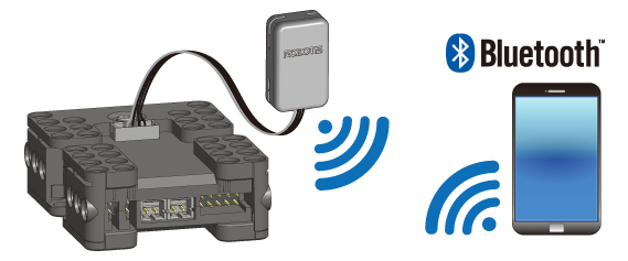
Note: You can use a smart phone to download motion and task files wirelessly to CM-200 using R+ m.Motion, see Motion Download for more information.
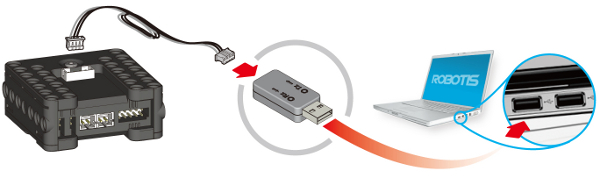
Connect to PC
To connect the CM-200 to the PC LN-101 is required
Wireless Communication
The CM-200 is compatible with BT-210 / BT-110 / ZIG-110 / BT-410 wireless communications modules.
Note: You can use smart device to download motion and task files to CM-200 wirelessly using R+ m.Motion, see Motion Download and Task Download for more information.
References
Certifications
Please inquire us for information regarding unlisted certifications.
FCC
Note: This equipment has been tested and found to comply with the limits for a Class A digital device, pursuant to part 15 of the FCC Rules. These limits are designed to provide reasonable protection against harmful interference when the equipment is operated in a commercial environment. This equipment generates, uses, and can radiate radio frequency energy and, if not installed and used in accordance with the instruction manual, may cause harmful interference to radio communications. Operation of this equipment in a residential area is likely to cause harmful interference in which case the user will be required to correct the interference at his own expense.
WARNING
Any changes or modifications not expressly approved by the manufacturer could void the user’s authority to operate
the equipment.