Introduction
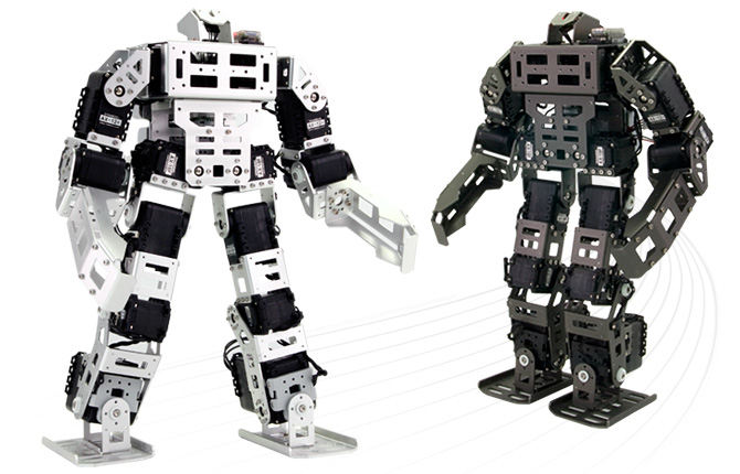
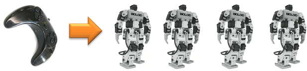
- Best humanoid robot with high-quality DYNAMIXEL AX-18F (legs)
- Strong, lightweight aluminum frames
- Excellent mobility such as turning during walking or high-speed walking
- Basic humanoid motions such as combat and soccer modes provided
- Self-position-correcting using Gyro sensor
- Gripper set and sensors included for various missions
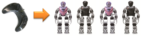
- Wireless remote included (BT-410 installed)
- Up-to-date version of RoboPlus- programming software- included
- Digital Packet communication and simple Daisy Chain cable arrangement
Getting Started
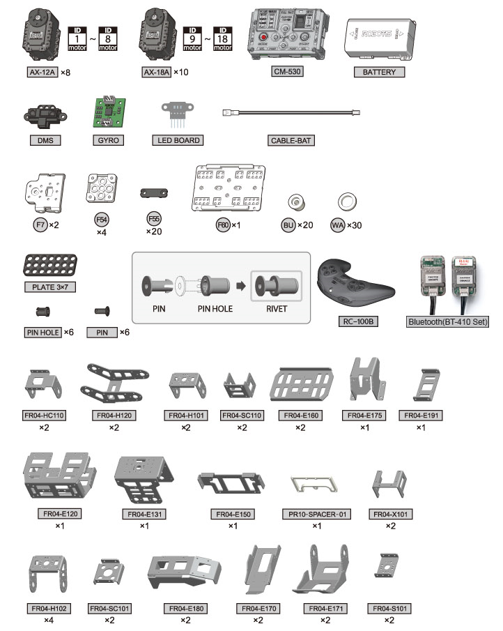
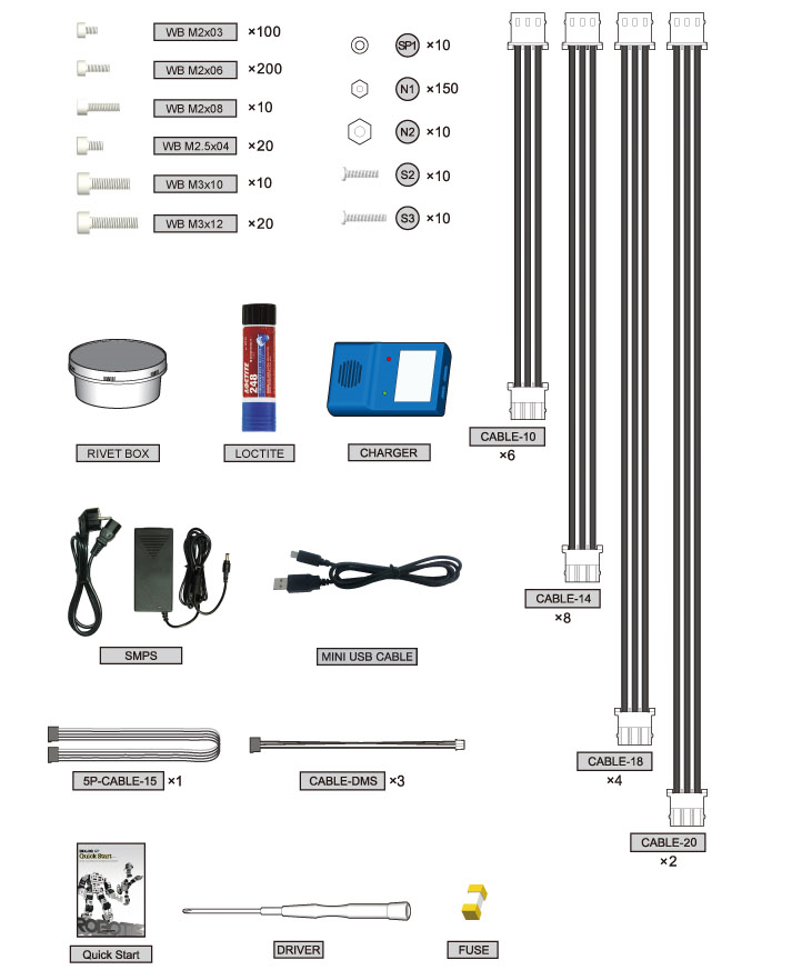
Part List
Operating
Downloading the Program
- Program for type A is installed by default in CM-530.
- You can find task codes and motion files for other actions on the Download page.
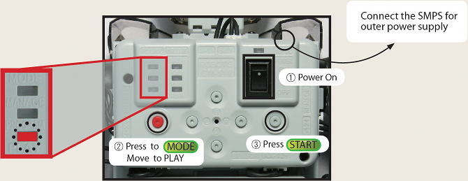
Turning the Robot on
- Turn the power switch on and the LED will start blinking.
- Use the MODE button to move the LED to “PLAY”. (The LED will move each time you press the MODE button)
- Press the START button. (Check whether the LED on “PLAY” is blinking)
- If the LED does not turn on, check the power cable/connection.
- If there are no problems with cable, recharge your battery. (Please refer to Charging for more information)
The power does not turn on.
- Is the battery properly connected?
- Is the battery fully charged?
- Is the battery fuse intact?
- Please refer Fuse Replacement for information on how to replace the fuse.
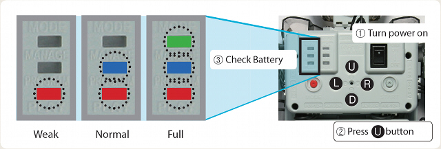
I want to check how much battery I have left.
Turn the CM-530 on and press the U button. The LED will turn on to show how much battery you have left as seen in the figure below.
The robot makes a continuous warning sound while moving.
- The alarm indicates that the robot is low on batteries. Immediately recharge your battery(Refer to Charge).
- If you do not replace the battery right away, the robot may turn off without warning and fall, which can cause severe damage.
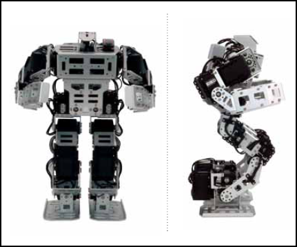
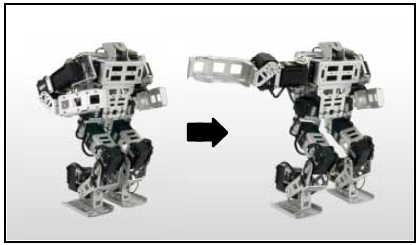
Checking the robot’s basic posture (To check whether the robot has been assembled correctly)
- When the robot is turned on, it defaults to the pose shown below.
-
Check the angles of the arms and legs. If they are different from the picture, go back to “Check Assembly Mode”.
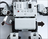
-
Check whether the cables have been assembled on the outer part of the leg.
NOTE : If the robot has been incorrectly assembled to an extent where it may be severely damaged, a warning sound will be activated. Also, the LED of the motor with the problem will turn on and release its torque to prevent damage.
Robot in Action
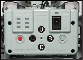
U: Soccer ModeD: Battle ModeLorR: Performance Mode
NOTE : Operating the robot with the RC-100 without selecting the mode will automatically start the soccer mode.
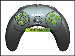
- Press the POWER/MODE button for 2 seconds to power on.
- Press the buttons below to control the robot.
Walking Motions
| Buttons | Motion | Buttons | Motion |
|---|---|---|---|
| U | Forward | D | Backward |
| L | Turn Left | R | Turn Right |
| U + L | Walk Forward + Left | U + R | Walk Forward + Right |
| L + 5 | Left Sidestep | L + 5 + 6 | Fast Left Sidestep |
| L + U + 5 | Left Forward Diagonal Step | L + D + 5 | Left Backward Diagonal Step |
| R + 5 | Right Sidestep | R + 5 + 6 | Fast Right Sidestep |
| R + U + 5 | Right Forward Diagonal Step | R + D + 5 | Right Backward Diagonal Step |
Standard
| Buttons | Motion | Buttons | Motion |
|---|---|---|---|
| 1 + U | Gets up facing up | 1 + D | Gets up facing down |
| 5+6+U+1 | Soccer Mode(Change Mode) | 5+6+D+3 | Battle Mode(Change Mode) |
| 5+6+L+2 | Performance Mode(Change Mode) | - | - |
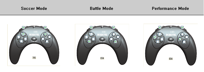
U: Soccer Mode
| Buttons | Motion | Buttons | Motion |
|---|---|---|---|
| 2 + U | Left Leg + Forward Kick | 4 + U | Right Leg + Forward Kick |
| 2 + D | Left Leg + Back Kick | 4 + D | Right Leg + Back Kick |
| 2 + L | Left Leg + Left Kick | 4 + L | Right Leg + Left Kick |
| 2 + R | Left Leg + Right Kick | 4 + R | Right Leg + Right Kick |
| 3 | Defense Standby | 3 + L | Block Ball + Left |
| 3 + U | Defense | 3 + R | Block Ball + Right |
D: Battle Mode
| Buttons | Motion | Buttons | Motion |
|---|---|---|---|
| 2 + U | Hit + Forward Attack | 3 | Defense |
| 2 + L | Hit + Left Attack | 2 + R | Hit + Right Attack |
| 4 + U | Upper Body Tackle | 4 + D | Lower Body Tackle |
| 4 + L | Left Strong Tackle | 4 + R | Right Strong Tackle |
L/R: Performance Mode
| Buttons | Motion | Buttons | Motion |
|---|---|---|---|
| 2 + U | Gretting | 2 + R | Handstand |
| 2 + D | Clap(Twice) | 3 + U | Roll on Side |
| 2 + L | Clap(337) | 3 + D | Push ups |
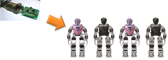
After mounting the IR receiver on CM-530 under control mode, you can set the channels to control it remotely by pressing the Aux button. If you change the channel of the controller, you must also change the channel of RC-100. On how to change the channel of RC-100, please refer to Changing RC-100’s Channel.
Setting the CM-530 IR Channels (Start + U/L/D/R)
| Buttons | Description |
|---|---|
| Start + U | Set the RC-100 channel as 1 |
| Start + L | Set the RC-100 channel as 2 |
| Start + D | Set the RC-100 channel as 3 |
| Start + R | Set the RC-100 channel as 4 |
My remote controller does not work properly.
- Set to control mode.
- Check whether the IR receiver has been properly connected.
- Check whether the remote controller is on. Replace the battery and try again.
- Point towards the IR receiver and try again.
- Check if there are others controlling robots nearby, which may cause wireless interferences.
We want to play soccer or battle with several robots.
- In order to play a game with several users, you must install the ZIG-110 set.
- ZIG-110 set is available at the Robotis shopping mall.
- Please refer to Controller and RC-100 for installation information.
Battery Charge
You may obtain Lithium polymer batteries from www.robotis-shop-en.com.
If the robot alarm sounds off during operations then recharge the battery.
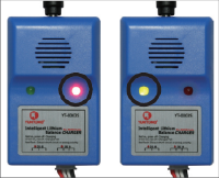
During charging the charger’s red LED turns on. When complete the green LED turns on.
-
Take the battery out
-
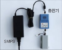
Connect the charger
-
Charge
Charging(Red LED), Complete(Green LED)
-
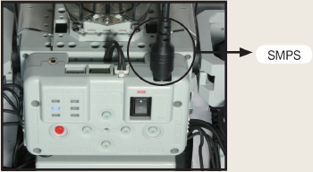
You can connect the robot to an external power source through SMPS.
-
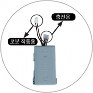
The battery is equipped with a connector to charge the battery and another to move the robot
Charging Time and Battery Life/Operating
Charging Time
- When fully discharged : 1~1.5 hour
- Leaving the battery fully discharged for too long may reduce its lifespan drastically.
- Time to charge the battery depends on the status of the battery(If the charging time or battery life becomes too short, you may need to replace your battery).
Caution
- Do NOT keep the battery connected with a robot or a charger.
- If you will not use the battery for a long time from now on, please keep it HALF-CHARGED.
- Do NOT put the battery with an environment with high temperature or humidity.
Tutorial
Screen Output
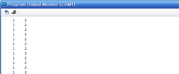
Objective for this tutorial is to print 1 and 2 on the output screen as below.
Write Task Code
-
Execute RoboPlus Task Program.
As seen in the picture below, go to
Start > All Programs > ROBOTIS > RoboPlus > Software > RoboPlus Taskto execute RoboPlus Task.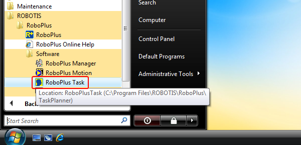
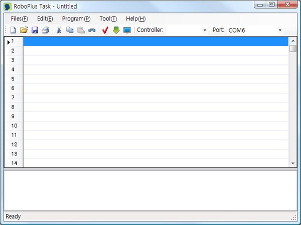
- RoboPlus Task Initial Screen
-
Select a Controller.
Double click an empty line or press
Enter, In theSelect Controlwindow, select the controller to use, then press theOKbutton.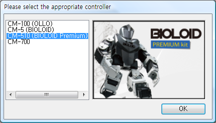
-
Generating
Start Program.Select
Start Programfrom theSelect Instruction Typewindow,Start Programwill be automatically generated in RoboPlus Task.
-
Input
Endless LoopcommandTo print the numbers on the screen endlessly, use the
Endless Loopcommand(Create a command line). Double click or pressEnteron an empty line between{and}of Start Program to invoke theSelect Instruction Typewindow. SelectLoop > Endless Loop(while(1))from the list.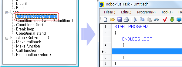
-
Input
LoadcommandUse
Loadcommand to input aPrintcommand, which is needed to print numbers on the screen. InsertExecute > Load (Assignment value)into an empty line between{and}ofEndless Loop.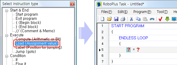
-
Load
1intoPrintChoose the left parameter ( ? ) among the
Loadparameters(Explanation on the parameter). The left parameter receives input from the right parameter. Double click the left parameter ( ? ), or pressEnterkey after clicking it once to invoke theSelect Parameter Window. SelectController > Printthen pressOK.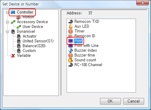
Select
Constant Numbers > Number > 1for the right parameter ( ? ) in the same way.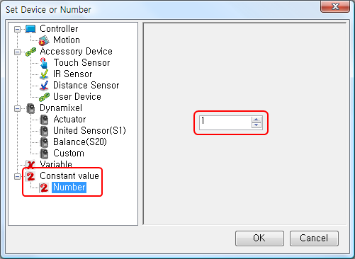
When both parameters of the
Loadcommand have been set, it should look like below.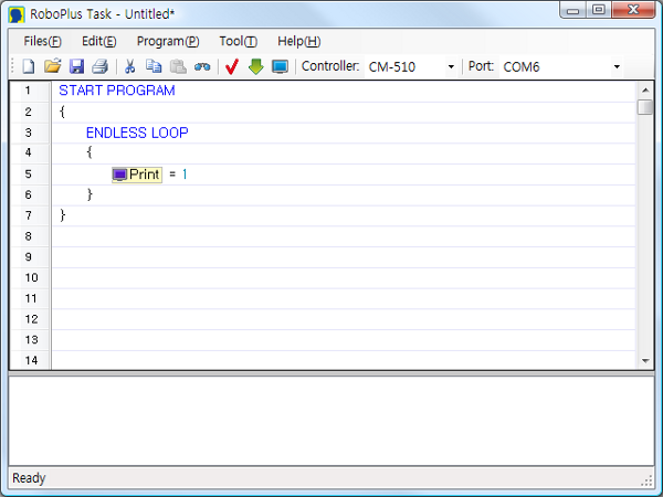
-
Load
2intoPrint with LineSelect
}underPrintcommand (at the end of the endless loop section), and add new lines by pressing theSpacekey. Repeat Steps 5 and 6 to input theLoadcommand and to inputController > Print with Lineand2. The final task code is shown below.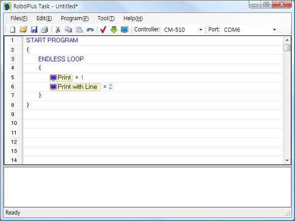
-
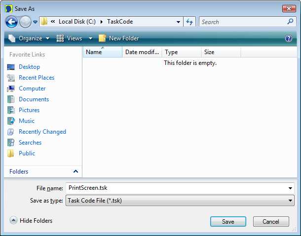
Save Task Code
Press Ctrl + S or the Save icon.
Download Task Code
Download the task code created above.(How to Download Task Code)
Execute Task Code
-
Open the Program Output Monitor
To see the output of the program, you must open the Program Output Monitor BEFORE executing the program. There are three ways to open the Program Output Monitor.
-
Click on the View Print of Program in the Download Program window
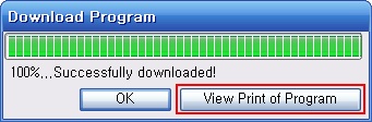
- Click on the
View Print of Programbutton in TOOLS. - Press
F5or click on View Print of Program (V) menu under Program (P).
-
-
Executing the Program
When you turn on the controller, the LED will blink, showing it is in standby mode. Press the MODE button to move it to PLAY, then press START to execute the downloaded task code. You should see “1” and “2” being printed on the Program Output Monitor.
Button & LED
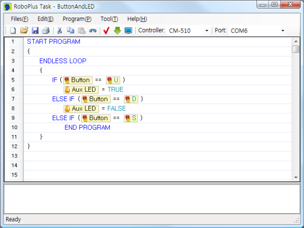
Objective for this tutorial is to program the U button to turn the AUX LED on and the D button to turn it off. Pressing the START button will end the program.
Write Task Code
Download Task Code
Download the task code created above.(How to Download Task Code)
Execute Task Code
Execute the program and check whether the AUX LED turns on when you press the U button and turns off when you press the D button. Press START button to end.
Download
| File Type | Download |
|---|---|
| Humanoid Task Code | Download |
| Humanoid Basic Motion File | Download |
| QuickStart Guide PDF File | Download |
References
Replacing Fuse
The fuse in the CM-510/CM-530 prevents it from overloading,which can damage the circuit.
If the CM-510/CM-530 does not turn on with the battery but turns on when connected to the SMPS, replace your fuse.
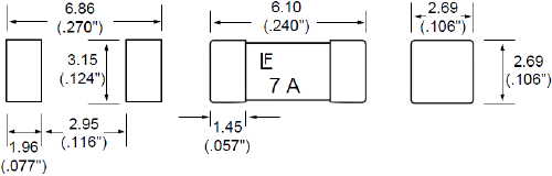
※ The size of the fuse is shown below. Use a 125V/5A~10A fuse.
※ How to replace the fuse
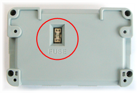
-
Find the fuse on the back of the CM-510/CM-530.
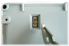
-
Use a pincette to replace the fuse with a new one.
DYNAMIXEL Management
DYNAMIXEL used as robot actuators possess many functions. This section explains how to change the dynamixel’s settings.
Changing the ID
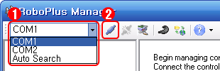
- Select the port the controller is connected to.
-
Click “Connect”.
- A list of connected dynamixels is shown on the left. Click on the dynamixel you wish to change the ID of.
- Click on the ID row in the Control Table.
-
Click on the ID List combo box to see a list of possible ID’s. Select the ID, then click Apply.
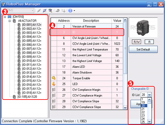
- To use in RoboPlus Motion and RoboPlus Task, the ID must be within the following ranges.
- The DYNAMIXEL’s ID must be between 0 and 25.
- The ID for AX-S1 should be set between 100 and 109.
Changing the Movement Mode
The dynamixel can operate in 2 different modes.
- Wheel Mode : Rotates 360 degrees like a regular motor.
- Joint Mode : Moves at a set angle with normal servo motors.
The mode can be changed using RoboPlus Manager. Once the mode is set, it will be maintained, even when turned off.
- Select the port the controller is connected to.
-
Click “Connect”.

- A list of connected DYNAMIXEL is shown on the left. Click on the DYNAMIXEL you wish to change the mode of. Then, click on the CW/CCW Angle Limit line in the Control Table.
-
To set to Wheel Mode, change the CW/CCW Angle Limit value to “0.” Or, simply click on the “Wheel Mode” button.
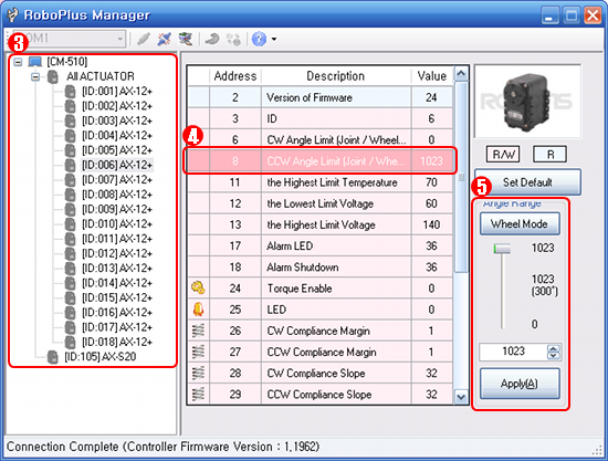
- To set to Joint Mode again, set the CW/CCW Angle Limit value to any number other than “0”. The initial values for Joint Mode are “0” for CW Angle Limit, and “1023” for CCW Angle Limit.
Troubleshooting
If you cannot find the dynamixel you are looking for using RoboPlus Manager, try the following :
- Connect just 1 DYNAMIXEL and check if there are any duplicate IDs. If you see a DYNAMIXEL on the left even though only 1 DYNAMIXEL is connected, there is a high probability of a duplicate ID. Change the ID immediately.
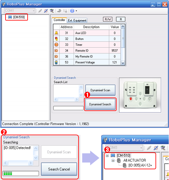
- If you are unable to find any DYNAMIXEL as in the image below, click on “DYNAMIXEL Search”. If the communication speed is not set to 1Mbps, the “DYNAMIXEL Search” function automatically resets the controller’s communication speed to 1Mbps to enable it to be recognized.
If the problem persists, your dynamixel may need repair. Please contact the service department of the company you purchased from.
ZIGBee Wireless Control
ZIGBee
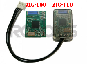
ZIG-100/110 uses ZIGBee for wireless communication. ZIGBee, like Bluetooth, is the communication technology commonly used in Personal Area Network (PAN). The communication quality of ZIGBee is better than that of IR, so it allows many users to control their robots without interferences.
CAUTION : Please note that not all products include a zigbee module and may need to be purchased separately.
Controller & ZIGBee
OLLO and Bioloid both use the RC-100, which uses IR communication method. To upgrade to the Zigbee communication method, you must purchase the ZIG-110 set separately. The ZIG-110 set includes one Zig-100 module, which is attached to the RC-100, and one Zig-110 module which is attached to the Controller.
NOTE : The modules in a single Zigbee set have been preconfigured to communicate with each other. Therefore, a module from one set may not work with a module from another set. Please be careful not to mix them up.
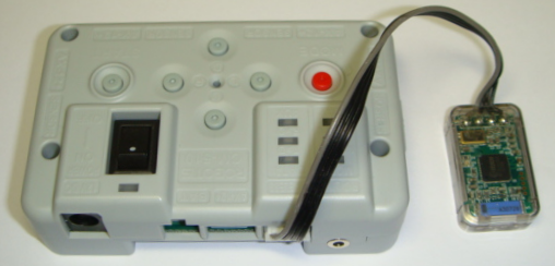
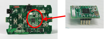
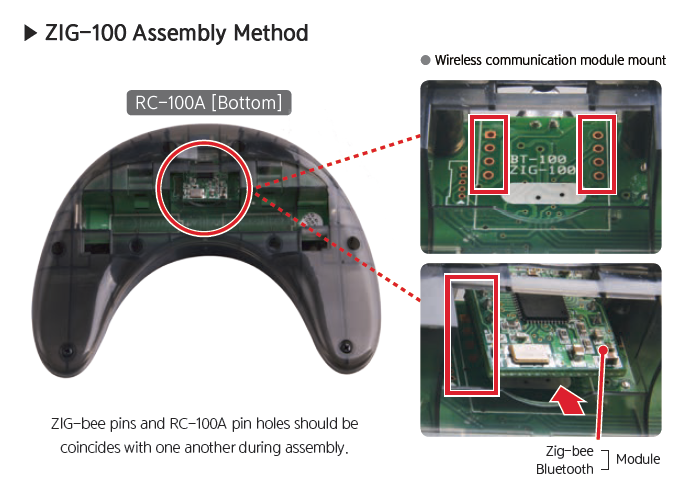
| ZIG-100 installed in RC-100 | ZIG-110 installed in CM-100 |
|---|---|
 |
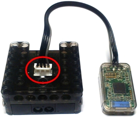 |
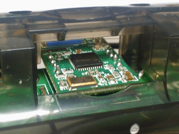
| ZIG-110 installed in CM-510 | ZIG-100 installed in CM-5 |
|---|---|
 |
 |
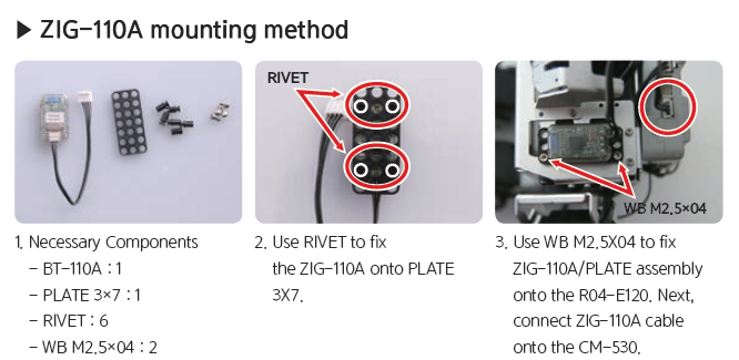
ZIG-110A Set Assembly Method(GP)
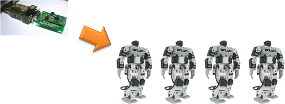
Control Multiple Robots
This method is to give out commands at once to several robots being used for dance or demonstration Gives out commands to the robot at once using the zigbee module’s broadcast mode
Bioloid(Entry/Advanced)
-
Communication with the Zig2Serial and various robots
-
Communication with the RC-100 and various robots
- To use the CM-5, connect the controller and ZIG-100 module together.
- Use the RoboPlus Manager to set the wireless ID of ZIG-100 module on the opposite party’s robot to 65535.
- No need to set the broadcast channel for communication.
- Use the RC-100 to give commands directly or use the Zig2Serial to give commands using the PC.
| Device | Channel Default Value | Whether or not the channel can be changed |
|---|---|---|
| CM-5 | 1 | Unchangeable |
| Zig2Serial | 1 | Changeable |
| RC-100 | 1 | Changeable |
The channel for the ZIG-100 mounted on the CM-5 is unchangeable. Thus, all users must set their channel to #1 for broadcast communication. All channels for the devises must pair to communicate.
Bioloid Premium Kit
-
Communication with the Zig2Serial and various robots
-
Communication with the RC-100 and various robots
- When using the CM-510, connect the ZIG-100 module with the controller.
- Use the RoboPlus Manager to change the opposite party’s wireless ID to 65535.
- The channel on the ZIG-110 connected to the controller it set to #4, so the channels on the Zig2Serial and RC-100 must be set to #4.
- How to change the RC-100 channel
- How to change the Zig2Serial channel
| Device | Channel Default Value | Whether or not the channel can be changed |
|---|---|---|
| CM-510 CM530 |
4 | Unchangeable |
| Zig2Serial | 1 | Changeable |
| RC-100 | 1 | Changeable |
The channel for the zigbee connected to the controller is not changeable. Thus, all users must set their channel to #4 for broadcast communicationAll channels for the devises must pair to communicate.
Adding Sensors
With the Bioloid Premium Kit, you can connect additional IR Sensor and Touch Sensor to the CM-530. For more information on each sensors, please click on the names of the sensors.
IR Sensor
- IR Sensor Applications
- The IR sensor can detects objects in front of the robot.
- It can also be used to detect object on the side when walking or moving.
Touch Sensor
- Touch Sensor Applications
- The touch sensor enables the robot to feel when it has been touched.
- For example, the sensor can be used to make the robot react to certain touches.
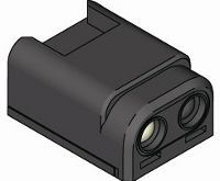
DMS(Distance Measuring Sensor)
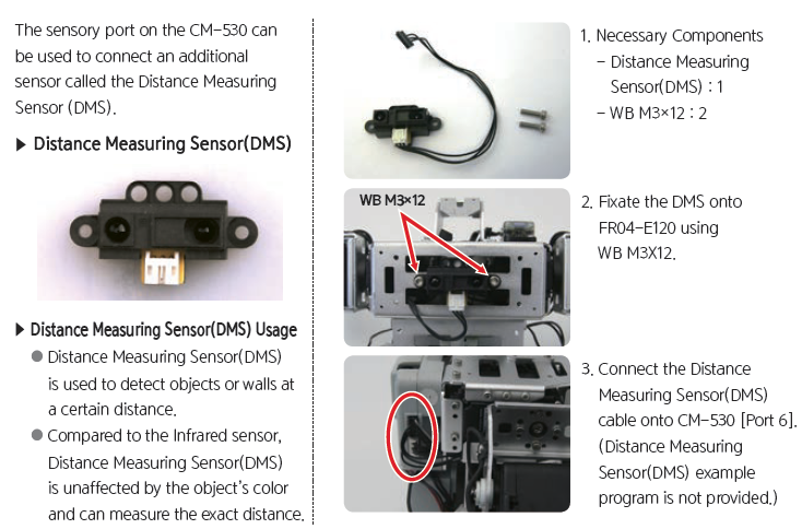
Make Your Own Sensor
You can make your own sensor with simple control functions using the ADC port and OUT port on CM-510/CM-530.
CAUTION : Connecting poorly designed circuits may damage the controller. Please be sure to acquire sufficient knowledge about circuits beforehand.
PIN Information
- Below is a pin diagram of CM-510’s external port.
- OUT : 5V Output
- VCC (5V)
- ADC : Can read analog signals made by users.
- GND
- NC : Not used
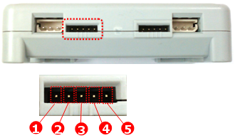
- Below is a pin diagram of CM-530’s external port.
- OUT1 : 3.3V Output (Maximum Allowed Current 0.3A)
- VCC (5V)
- ADC : Can read analog signals made by users.
- GND
- OUT2 : 3.3V Output (Maximum Allowed Current 0.3A)
NOTE : Please use the 5P Cable when using other sensors. The 5P cable can be purchased from ROBOTIS.
Controlling User’s Device
External Output Control
Below is an example of an LED circuit to turn the LED on and off using the OUT port (Pin 1). You need to adjust the amound of resistance depending on the type of controller and/or the type of LED.
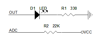
A high signal can be sent to the OUT port using RoboPlus Task.
- Select the user’s device in the writable parameter such as LOAD and CALCULATE, then select the port on which the device is connected.
- Then, set the high signal to the readable parameter using a constant.
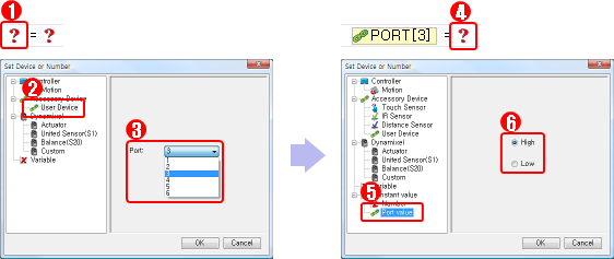

When the code above is executed, high signal will be sent to the OUT port of the device connected to PORT 3, and the LED will turn on.
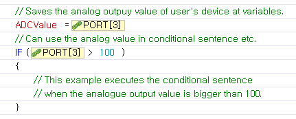
Reading the ADC Value
Most of the sensors used in robots, such as IR sensors and distance sensors, support analog output. The CM-510 can use its external ports to read the sensor’s analog output signals. These sensors may be designed by the user or bought from a store.
- Below is an image of a tilt sensor. When the sensor is tilted, it prints the tilted value as the analog singal.
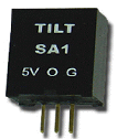
- The left pin of the tilt sensor is 5V VCC. The center is an analog signal output pin, and the right pin is GND. This sensor can be used by connecting its pins to the corresponding pins on CM-510’s external port. To try for yourself, please refer to the pin information for CM-510’s external ports.
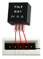
- You can incorporate the sensor’s analog output to your robot’s movements as in the example below.