
Introduction
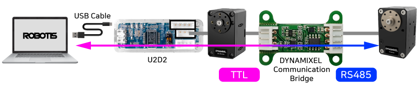
The DYNAMIXEL Communication Bridge works as a communication converter between TTL (3 Pin JST Type connector) and RS485 (4 Pin JST Type connector) of DYNAMIXEL.
NOTE
TTL and RS485 ports in the U2D2 interface are separately connected to the master PC, however, the data line between TTL and RS485 ports are not connected to each other.
Thus, Instructions Packets such as Broadcast Ping, Sync Read and Bulk Read over TTL to RS485 and vice versa are not feasible through the U2D2 interface only.
- For more detailes about Instruction Packet, see DYNAMIXEL Protocol 1.0 or Protocol 2.0 depending on what DYNAMIXEL is in use.

Unlike the U2D2, the DYNAMIXEL Communication Bridge features a signal conversion between TTL to RS485, which allows Broadcast Ping, Sync Read, and Bulk Read instructions from mixed types of communication.
Specifications
| Item | Specifications |
|---|---|
| Operating Voltage | 3.5 V ~ 30.0 V |
| Current Raiting | 3.0 A |
| Baud Rate | Max 4 Mbps |
![]()
DANGER
(Ignoring these warnings may cause serious injury or death)
- Never place items containing water, flammables/open flames, or solvents near the product.
- Never place fingers, arms, toes, and other body parts near product during operation.
- Cease operation and remove power from the product if the product begins to emit strange odors, noises, or smoke.
- Keep product out of reach of children.
- Check input polarity before installing or energizing wiring or cables.
![]()
CAUTION
(Ignoring these warnings may cause mild injury or damage to the product)
- Always comply with the product’s offical operating environment specifications including input voltage, current, and operating temperature.
- Do not insert blades or other sharp objects during product operation.
![]()
ATTENTION
(Ignoring these warnings may cause minor injury or damage to the product)
- Do not disassemble or modify the product.
- Do not drop the product or apply strong impacts.
- Do not connect or disconnect DYNAMIXEL cables while power is being supplied.
Layout
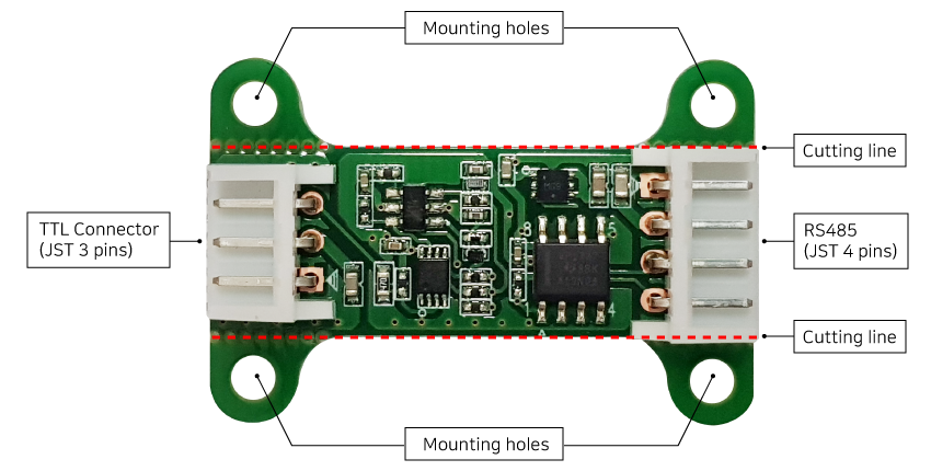
Layout - Front
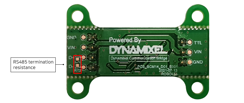
Layout - Back
NOTE: VDD is the same terminology as the Vin printed back of the DYNAMIXEL Communication Bridge.
Description
-
TTL (JST 3 Pins) / RS485 Connecters (JST 4 Pins) : 3 and 4 Pin JST connectors for TTL / RS458 communication.
-
Mounting holes : Used to mount on other devices. Mounting holes can be removed if not used by snapping along the V-cut line.
-
RS485 Termination resistance: Reserved space to install RS485 termination resistor. 1608 size(1.6 x 0.8 mm) chip resistor can be used.
Connection Examples
-
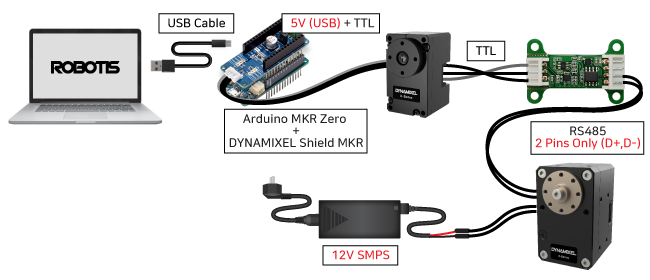
If the operating voltages of all DYNAMIXELs are the same, see the following images.

Powering the DYNAMIXEL from Master Device.
Powering the DYNAMIXEL from external power source.
-
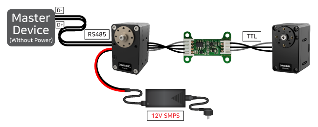
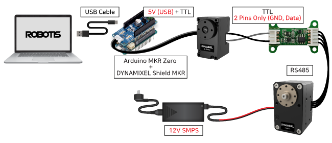
If the operating voltages of DYNAMIXELs are different, see the following images.
Powering the DYNAMIXEL Communication Bridge from the RS485 connector side.
Powering the DYNAMIXEL Communication Bridge from the TTL connector side.
WARNING:
VDDpins (See Layout) of DYNAMIXEL Communication Bridge between a RS485 and TTL connector are connected each other. In case the TTL and RS485 connectors use different power, be sure to connect only oneVDDto the DYNAMIXEL Communication Bridge for the product safety.
Reference
Connector Information
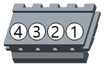
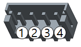
| Item | TTL | RS-485 |
|---|---|---|
| Pinout | 1 GND2 VDD3 DATA |
1 GND2 VDD3 DATA+4 DATA- |
| Diagram |  |
 |
| Housing | 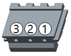 JST EHR-03 |
 JST EHR-04 |
| PCB Header | 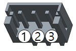 JST B3B-EH-A |
 JST B4B-EH-A |
| Crimp Terminal | JST SEH-001T-P0.6 | JST SEH-001T-P0.6 |
| Wire Gauge for DYNAMIXEL | 21 AWG | 21 AWG |