
Introduction
What is OP2?
Open Platform Humanoid Project
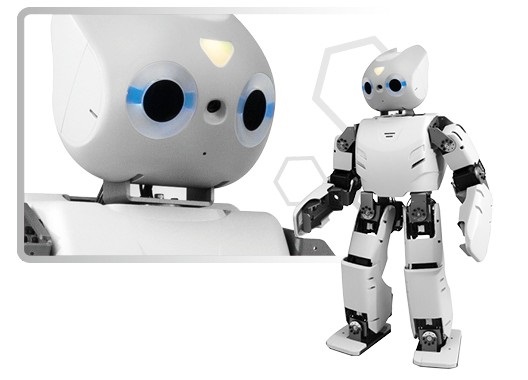
ROBOTIS OP2 (as known as “DARWIN 2” or DARWIN-OP2”) has been upgraded with greater computational performance compare to ROBOTIS OP (as known as “DARwIn-OP”).
Despite the change in name the robot may be colloquially still be called “Darwin”. The only major change comes from the upgrade in computational power.
When ROBOTIS OP was first released it was stated that it supported Windows OS.
This claim is, and remains, technically true. However, in practice installing Windows is impossible due to the 4GB cap of the embedded SSD from ROBOTIS OP’s PC.
The scant 4GB made difficult installing the later releases of Ubuntu and significant workaround was required to be able to install the later Linux releases.
ROBOTIS OP2 upgrade is aimed at eliminating the difficulties relating to computing from the previous generation.
You can now focus your efforts more into developing the robot and less on devoting resources for computing.
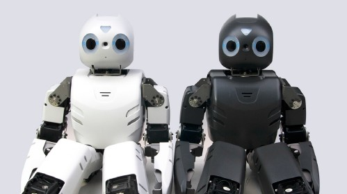
- Visual differences with ROBOTIS OP:
- Other than the color difference, the overall appearance remains unchanged.
- Here are some mechanical differences :
- New mini HDMI port connector on the ROBOTIS OP2
- Location of the ports
- ROBOTIS OP2 no longer has the 3.5mm microphone and audio jacks
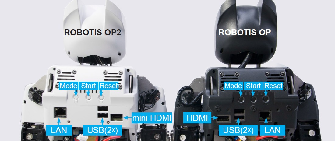
Here are some mechnamical differences
- Advantages of ROBOTIS OP2 compared to ROBOTIS OP
- User-replaceable SSD
- User-replaceable RAM
- Significantly increased computation power
- Reduced size of the PC
- Reduced size of the management controller (CM-730 ⇨ CM-740)
- Hardware Spec Comparison
| DARWIN OP | ROBOTIS OP2 | |
|---|---|---|
| CPU | Intel Atom Z530 @1.6GHz single core |
Intel Atom N2600 @1.6GHz dual core |
| RAM | 1GB DDR2 (fi xed capacity) |
up to 4GB DDR3 204-pin SO-DIMM module (user-replaceable) |
| Storage | 4GB NAND flash IDE100 (fixed capacity) |
half-size mSATA module (32GB) (user-replaceable) |
| LAN speed | 100 Mbps | 1 Gbps |
| Installable OS | Linux only (32-bit) | any Linux release (32-bit) any Windows release (32-bit) |
| wi-fi | 802.11g | 802.11n (2.4GHz-only) |
ROBOTIS OP2 is an affordable, miniature-humanoid-robot platform with advanced computational power, sophisticated sensors, high payload capacity, and dynamic motion ability to enable many exciting research and education activities.
Safety Information
CAUTION : ROBOTIS will not be responsible for any loss or damage whatsoever caused resulting from user’s negligence or misuse of the product.
- Read the instruction carefully before getting started.
- Not suitable for children under 15 years old.
- Do not use any other tools other than those provided in the kit.
- Keep the robot away from your face and body when the robot is operating.
- Prevent from getting your fingers stuck between frames.
- Do not place the robot near water, heat or fire.
- Only use the battery and charger included in the kit.
- Gears must be replaced after long excessive use.
Package Contents
Check your ROBOTIS OP2 package for the following items.
| No | Item | Quantity |
|---|---|---|
| 1 | Fully-assembled ROBOTIS OP2 robot | 1 |
| 2 | USB Thumb Drive (with recovery software) | 1 |
| 3 | Fuse | 2 |
| 4 | Color Cards | 7 |
| 5 | Quick Start Manual | 1 |
| 6 | Power Cable | 1 |
| 7 | DC Power Supply | 1 |
| 8 | Spare Cables | 1 pack |
| 9 | Red Ball | 1 |
| 10 | Battery Pack | 3 |
| 11 | Battery Charger | 1 |
| 12 | Wrench & Screw Driver | 1 set |
| 13 | Spare Bolts and Nuts | 1 pack |
| 14 | Ethernet Cable | 1 |
| 15 | Hard Case | 1 |
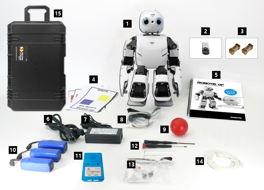
NOTE : Korean version offers a different type of charger.
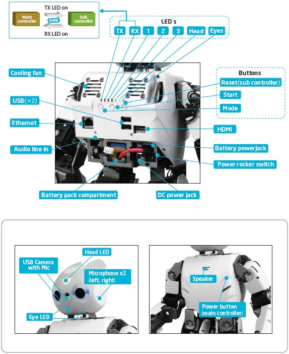
Layout
Charging Battery
This section describes how to charge a battery using the provided charger.
Use either of instructions depending on a provided charger.
Using LBC-010
The following video provides instructions on how to charge a battery using the LBC-010.
Using IMAX B6MINI CHARGER
Follow the next instruction and learn how to charge a battery using IMAX B6MINI CHARGER.
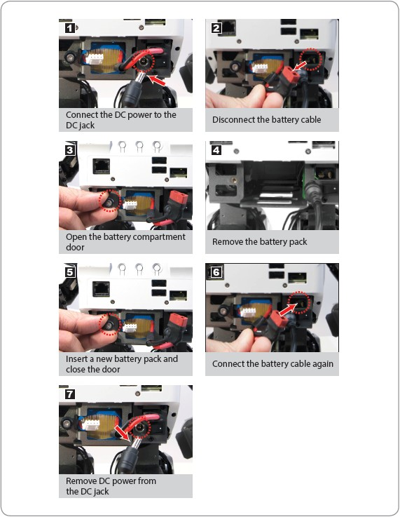
Battery Hot Swap
One distinguishing feature of ROBOTIS OP2 is its ability to change the battery without the need of shutting down.
To replace the battery during operation, please follow the procedures below.
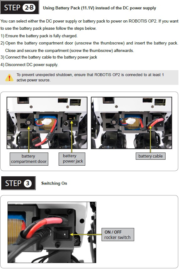
Quick Start
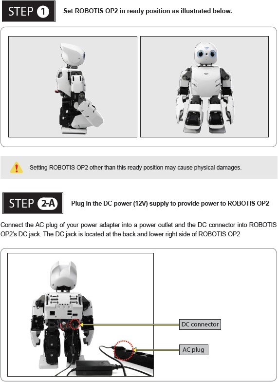
Power On
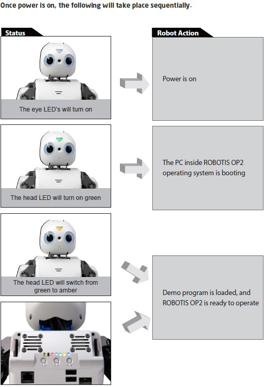
Execute Demo Program
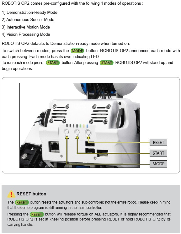
Running Demonstration Programs
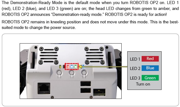
Demonstration Ready Mode
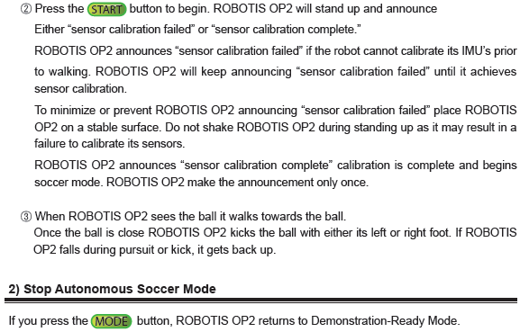
Autonomous Soccer Mode
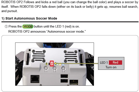
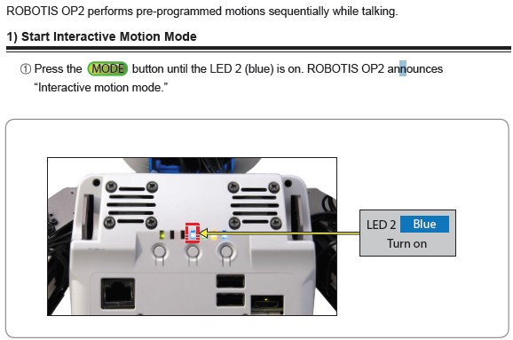
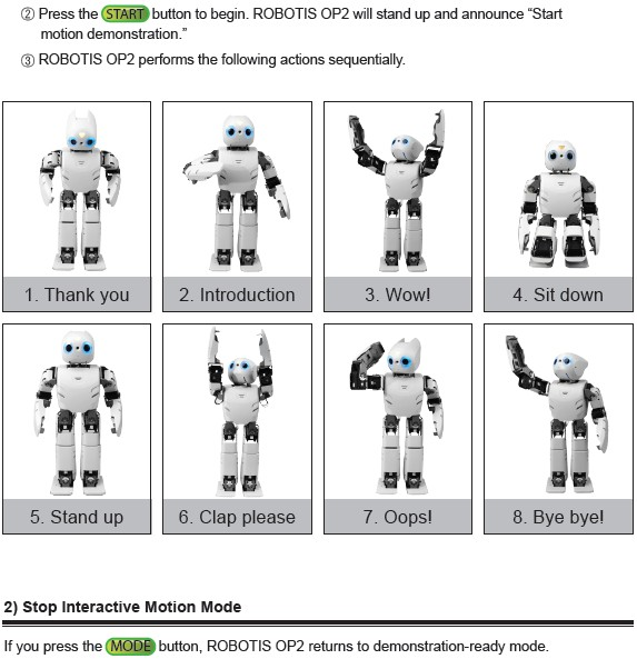
Interactive Motion Mode
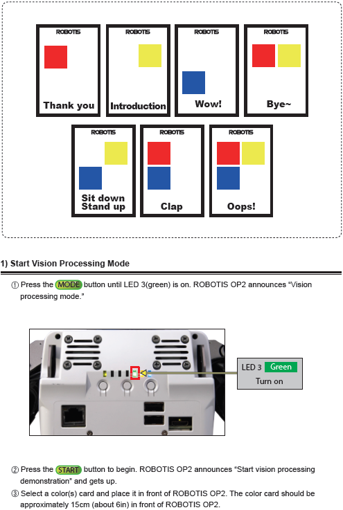
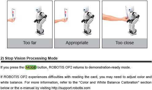
Vision Processing Mode
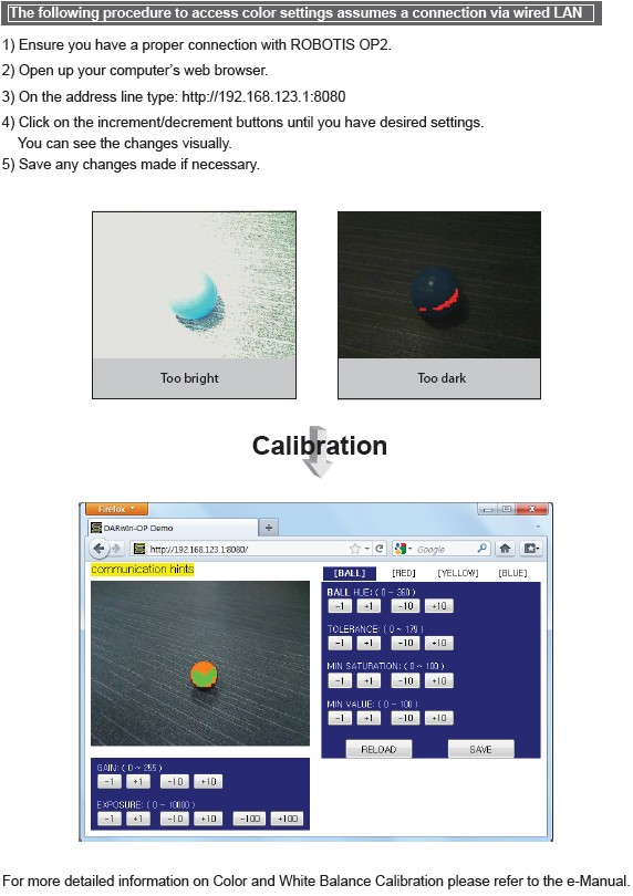
Camera Calibration
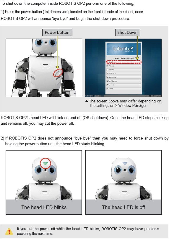
Power Off
Programming Guide
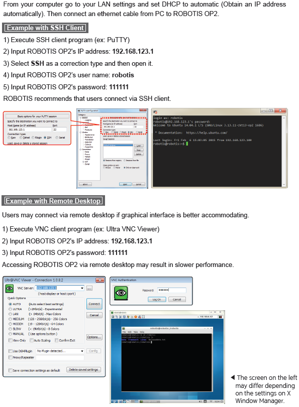
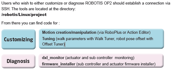
Connect to OP2
Development Environment
Source Code
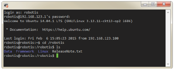
You may find the source code directory at /robotis from ROBOTIS OP2’s PC.
The pre-installed source code may be updated without prior notice. Please check for updates periodically. You may obtain updated source code at the following website https://sourceforge.net/projects/darwinop/files/
We strongly suggest you to practice the included tutorial programs installed at ‘/robotis/Linux/project/tutorial’ in ROBOTIS OP2’s PC.
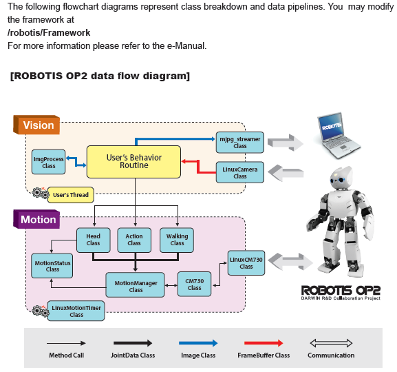
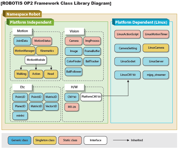
Framework


Software Utilities
Recovery Software
The supplied USB thumb drive contains the same software that comes installed with ROBOTIS
OP2.
You may obtain updates softwares at the link below.
https://sourceforge.net/projects/darwinop/files/Software/Main%20Controller/Recovery%20USB/
Software could be updated without prior notice. Please check the site periodically for updated information.
NOTE: Please refer to Clonezilla Recovery for OP section for instructions using recovery image.
Useful Information
You may find other ROBOTIS OP2-related softwares at:
https://sourceforge.net/projects/darwinop/files/
- For any other inquiries send us an email.
- International :
contactus2@robotis.com - Korea :
korea@robotis.com
- International :
- Third party terminal client
- PuTTY : http://www.chiark.greenend.org.uk/~sgtatham/putty/
- VNC : http://www.realvnc.com/
- ZOC : http://www.emtec.com/zoc/
- RBrowser (for Mac users) : http://www.rbrowser.com/
- Chicken of the VNC (for Mac users) : http://sourceforge.net/projects/cotvnc/
References
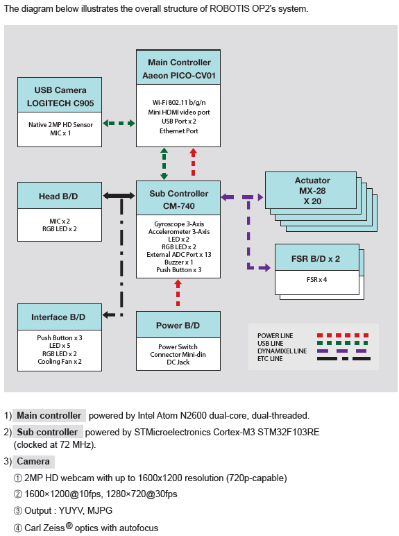
System Block Diagram
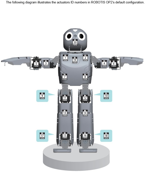
ID Map
Warranty
ROBOTIS OP2 includes the following warranty:
A. 90 days warranty against manufacture defects (RMA required) *
B. Local Maintenance Service (by local partner) : 1 years **
- Re-installation of S/W and fi rmware
- Replacement for cable/gear/screw (RMA required – exempt from faulty return)
- Replacement for faulty frame/cover/actuator (RMA required)
C. Core System Maintenance Service (by ROBOTIS) : 1 years
- Replacement for faulty PC/sub-boards (RMA required)
- Maintenance for actuator/sub-boards (RMA required)
- Maintenance for PC (RMA required, additional fee applies)
D. Parts replacement for malfunctions during normal operation for 1 years.
* Please download RMA Return Material Authorization
No return shipping will be accepted without a RMA number issued by ROBOTIS.
** Customers who require extended warranty period may purchase another “1 year warranty” from ROBOTIS before their standard warranty period is over.
Important Notice:
-
Product registration is required for all customers. http://support.robotis.com
-
Parts replacement can only be done through RMA(Return Material Authorization) application.
-
After the initial 90 days, shipping fee is not covered under warranty.
- Warranty does NOT cover ordinary wear/tear, any accident or damage caused by followings.
- Physical damage equivalent to dropping the robot from 20cm or higher
- Disabling system safety function (DYNAMIXEL Overload Shutdown)
- Dangerous movement (jump, roll, fi ght) or excessive operation without rest
- Any liquid or unauthorized chemical material to the robot
- Unauthorized power or electric shock applied to the robot
- Improvising core system programming area.
- Direct check-up service
Evaluation, maintenance and quality assurance of assembled robot can be provided by ROBOTIS only.
RMA is required and additional fee may apply. Service will not be rendered for seriously customized hardware.
Certifications
Please inquire us for information regarding unlisted certifications.
FCC
Note: This equipment has been tested and found to comply with the limits for a Class A digital device, pursuant to part 15 of the FCC Rules. These limits are designed to provide reasonable protection against harmful interference when the equipment is operated in a commercial environment. This equipment generates, uses, and can radiate radio frequency energy and, if not installed and used in accordance with the instruction manual, may cause harmful interference to radio communications. Operation of this equipment in a residential area is likely to cause harmful interference in which case the user will be required to correct the interference at his own expense.
WARNING
Any changes or modifications not expressly approved by the manufacturer could void the user’s authority to operate
the equipment.
Sub Controller(CM-740)
Download ZIPFrameworkDownload PDFSchematicsDownload ZIPReference Guide
You can also get information about the gyroscope and accelerometer.
| Feature | Specifications |
|---|---|
| CPU | STMicroelectronics 32F103RE ARM Cortex 32-bit CPU (clocked @ 72MHz) (512KB Flash, 64KB SRAM ) |
| Interface | 1x LED , 1 x Buzzer |
| External ports | 3 x ADC /I/O Ports |
| Sensor | 3-axis gyroscope , 3-axis accelerometer, supply voltage sensor |
| Communication | USB Port, Serial Port , 5x TTL Ports (for DYNAMIXEL) |
| Audio & Mic Amp | Audio amp gain : 20, mic amp gain : 2027 |
| ETC | DYNAMIXEL Power Control Unit, Head board port, Interface board port. |
| External supply voltage | 8V ~ 14.8v |
| Current consumption | Maximum 200mA , Standby 130mA |
| Dimensions | 80.0mm x 43.0mm x 20.0mm |
| Operation temperature | -65°C to +80°C |
| Weight | 26g |
Control Table
Control Table consists of data regarding the current status and operation of CM-740. The user can control CM-740 by changing data of Control Table via Instruction packet.
EEPROM and RAM
Data in RAM area is reset to initial values whenever the power is turned on while data in EEPROM area is kept once values are set even if the power is turned off.
Address
Represents the location of data. To read from or write data to the control table the user should assign the correct address in the Instruction packet.
Access
CM-740 has two kinds of data: Read-only data, used mainly for sensing, and read-and-write data used for driving.
Initial Value
In case of data in the EEPROM Area, the initial values on the right side of the below Control Table are the factory default settings.
In case of data in the RAM Area, the initial values on the right side of the following control table are the ones when the power is turned on.
Highest/Lowest Byte
In the Control table, some data share the same name, but they are attached with (L) or (H) at the end of each name to distinguish the address. This data requires 16-bit, but it is divided into 8bit each for the addresses (low) and (high). These two addresses should be written with one Instruction Packet simutaneously.
EEPROM Area
| Address | Name | Description | Access | Init Value |
|---|---|---|---|---|
| 0 (0X00) | Model Number(L) | model number low byte | R | 0(0X00) |
| 1 (0X01) | Model Number(H) | model number high byte | R | 116 (0X74) |
| 2 (0X02) | Version of Firmware | firmware version | R | - |
| 3 (0X03) | ID | DYNAMIXEL ID | RW | 200 (0XC8) |
| 4 (0X04) | Baud Rate | DYNAMIXEL baud rate | RW | 1 (0X01) |
| 5 (0X05) | Return Delay Time | Return Delay Time | RW | 0 (0X0) |
| 16 (0X10) | Status Return Level | Status Return Level | RW | 2 (0X02) |
RAM Area
| Address | Name | Description | Access | Init Value |
|---|---|---|---|---|
| 24 (0X18) | DYNAMIXEL Power | DYNAMIXEL On/Off | RW | 0 (0X00) |
| 25 (0X19) | LED Pannel | LED Pannel On/Off | RW | 0 (0X00) |
| 26 (0X1A) | LED 5 (L) | LED 5 low byte | RW | 0 (0X00) |
| 27 (0X1B) | LED 5 (H) | LED 5 high byte | RW | 0 (0X01) |
| 28 (0X1C) | LED 6 (L) | LED 6 low byte | RW | 0 (0X00) |
| 29 (0X1D) | LED 6 (H) | LED 6 high byte | RW | 0 (0X01) |
| 30 (0X1E) | Button | Button status | R | - |
| 38 (0X26) | Gyro_Z(L) | Gyroscope Z-axis low byte | R | - |
| 39 (0X27) | Gyro_Z(H) | Gyroscope Z-axis high byte | R | - |
| 40 (0X28) | Gyro_Y(L) | Gyroscope Y-axis low byte | R | - |
| 41 (0X29) | Gyro_Y(H) | Gyroscope Y-axis high byte | R | - |
| 42 (0X2A) | Gyro_X(L) | Gyroscope X-axis low byte | R | - |
| 43 (0X2B) | Gyro_X(H) | Gyroscope X-axis high byte | R | - |
| 44 (0X2C) | ACC_X(L) | Accelerometer X-axis low byte | R | - |
| 45 (0X2D) | ACC_X(H) | Accelerometer X-axis high byte | R | - |
| 46 (0X2E) | ACC_Y(L) | Accelerometer Y-axis low byte | R | - |
| 47 (0X2F) | ACC_Y(H) | Accelerometer Y-axis high byte | R | - |
| 48 (0X30) | ACC_Z(L) | Accelerometer Z-axis low byte | R | - |
| 49 (0x31) | ACC_Z(H) | Accelerometer Z-axis high byte | R | - |
| 50 (0X32) | Present Voltage | Current Voltage | R | - |
| 51 (0X33) | MIC 1 (L) | Mic 1 low byte | R | - |
| 52(0x34) | MIC 1 (H) | Mic 1 high byte | R | - |
| 53(0x35) | ADC 2(L) | ADC channel 2 low byte | R | - |
| 54(0x36) | ADC 2(H) | ADC channel 2 high byte | R | - |
| 55(0x37) | ADC 3(L) | ADC channel 3 low byte | R | - |
| 56(0x38) | ADC 3(H) | ADC channel 3 high vyte | R | - |
| 57(0x39) | ADC 4(L) | ADC channel 4 low byte | R | - |
| 58(0x3A) | ADC 4(H) | ADC channel 4 high byte | R | - |
| 59(0x3B) | ADC 5(L) | ADC channel 5 low byte | R | - |
| 60(0x3C) | ADC 5(H) | ADC channel 5 high byte | R | - |
| 61(0x3D) | ADC 6(L) | ADC channel 6 low byte | R | - |
| 62(0x3E) | ADC 6(H) | ADC channel 6 high byte | R | - |
| 63(0x3F) | ADC 7(L) | ADC channel 7 low byte | R | - |
| 64(0x40) | ADC 7(H) | ADC channel 7 high byte | R | - |
| 65(0x41) | ADC 8(L) | ADC channel 8 low byte | R | - |
| 66(0x42) | ADC 8(H) | ADC channel 8 high byte | R | - |
| 67(0x43) | MIC 2 (L) | Mic 2 low byte | R | - |
| 68(0x44) | MIC 2 (H) | Mic 2 high byte | R | - |
| 69(0x45) | ADC 10(L) | ADC channel 10 low byte | R | - |
| 70(0x46) | ADC 10(H) | ADC channel 10 high byte | R | - |
| 71(0x47) | ADC 11(L) | ADC channel 11 low byte | R | - |
| 72(0x48) | ADC 11(H) | ADC channel 11 high byte | R | - |
| 73(0x49) | ADC 12(L) | ADC channel 12 low byte | R | - |
| 74(0x4A) | ADC 12(H) | ADC channel 12 high byte | R | - |
| 75(0x4B) | ADC 13(L) | ADC channel 13 low byte | R | - |
| 76(0x4C) | ADC 13(H) | ADC channel 13 high byte | R | - |
| 77(0x4D) | ADC 14(L) | ADC channel 14 low byte | R | - |
| 78(0x4E) | ADC 14(H) | ADC channel 14 high byte | R | - |
| 79(0x4F) | ADC 15(L) | ADC channel 15 low byte | R | - |
| 80(0x50) | ADC 15(H) | ADC channel 15 high byte | R | - |
Address Function Help
Model Number
Represents the Model Number.
Firmware Version
Represents the firmware version.
ID
Is a unique number to identify DYNAMIXEL.
Values range from 0 (0x00) to 253 (0xFD), Value 254 (0xFE) is used as the Broadcast ID.
If the Broadcast ID is used to transmit Instruction Packet, then it can command to all DYNAMIXEL’s.
NOTE : Please be careful not to duplicate the ID of connected DYNAMIXEL’s.
Baud Rate
Represents the communication speed. 0 (0x00) to 254 (0xFE) can be used for it. This speed is calculated by using the below formula.
Speed(BPS) = 2000000/(Data+1)
| Data | Set BPS | Target BPS | Tolerance |
|---|---|---|---|
| 1 | 1000000.0 | 1000000.0 | 0.000 % |
| 3 | 500000.0 | 500000.0 | 0.000 % |
| 4 | 400000.0 | 400000.0 | 0.000 % |
| 7 | 250000.0 | 250000.0 | 0.000 % |
| 9 | 200000.0 | 200000.0 | 0.000 % |
| 16 | 117647.1 | 115200.0 | -2.124 % |
| 34 | 57142.9 | 57600.0 | 0.794 % |
| 103 | 19230.8 | 19200.0 | -0.160 % |
| 207 | 9615.4 | 9600.0 | -0.160 % |
NOTE : Maximum Baud Rate error of 3% is within the tolerance of UART communication.
Return Delay Time
Is the delay time per data value that takes from the transmission of Instruction packet until the return of Status packet.
0 (0x00) to 254 (0xFE) can be used. The delay time per data value is 2 microseconds (usec).
If the data value is delayed by 10, 20 usec the initial value is 250 (0xFA) (i.e., 0.5 msec).
Status Return Level
Decides how to return Status packet. There are three possibilities:
| Value | Return of Status Packet |
|---|---|
| 0 | No return against all commands (Except PING Command) |
| 1 | Return only for the READ command |
| 2 | Return for all commands |
NOTE : When Instruction packet is Broadcast ID, Status packet is not returned regardless of Status return level.
DYNAMIXEL Power
| Value | Meaning |
|---|---|
| 0 | Turn off the power of all DYNAMIXEL’s connected to CM-740. |
| 1 | Turn on the power of all DYNAMIXEL’s connected to CM-740. |
LED Pannel
| BIT | 7 ~ 3 | 2 | 1 | 0 |
|---|---|---|---|---|
| Value | X | LED4 | LED3 | LED2 |
If each bit is SET, applicable LED lights up.
If each bit is RESET, applicable LED goes off.
EX) When the LED Panel = 3 (00000101), the LED4 and LED2 light up.
LED5 / LED6
| BIT | 15 | 14 ~ 10 | 9 ~ 5 | 4 ~ 0 |
|---|---|---|---|---|
| Value | X | the value of blue light | the value of green light | the value of red light |
LED HEAD/ LED EYE is 3 color LED. It can represent the value of 32 steps by colors.
It can be represent by controling the value of light by colors.
BUTTON STATUS
| BIT | 7 ~ 2 | 1 | 0 |
|---|---|---|---|
| Value | X | the state value of START button | the state value of MODE button |
It is the value which represents the state of buttons.
If the bit is SET, it represents that the button is pressed.
If the bit is RESET, it represents that the button isn’t pressed.
GYRO / ACC
The following picture is the direction of axis at CM-740.
The Gyroscope and Accelerometer is 10mm distant respectively from the central axis of Dawin.
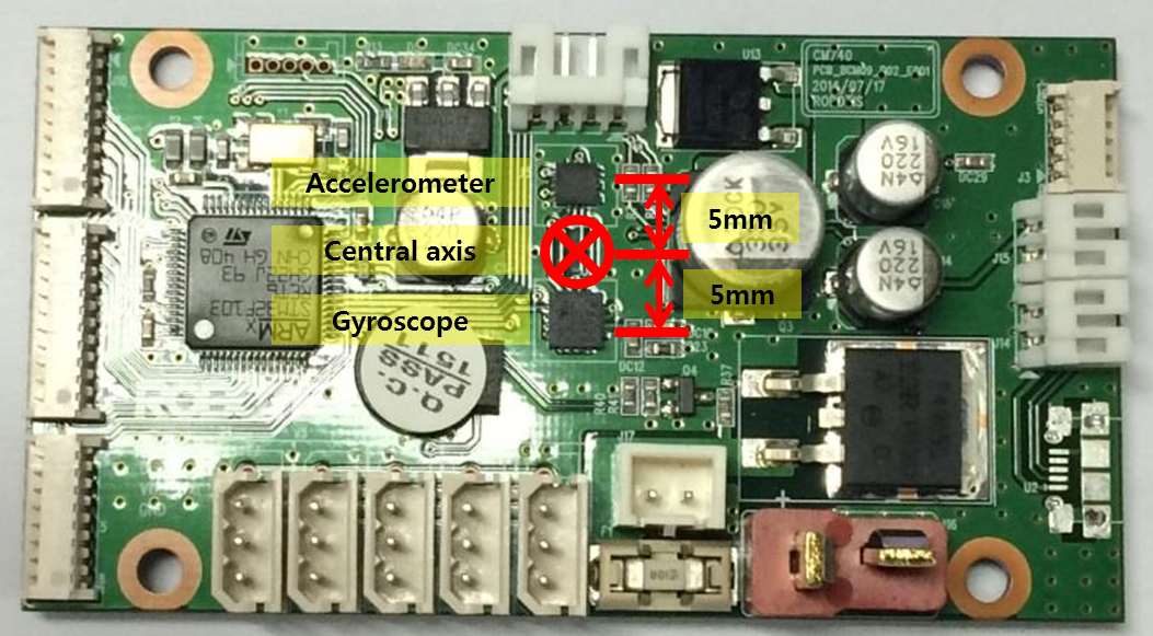
The positions of central axis and sensor at Dawin
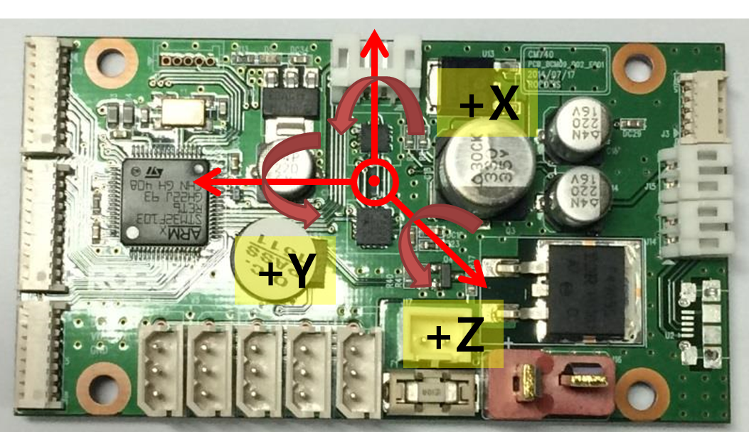
Gyroscope
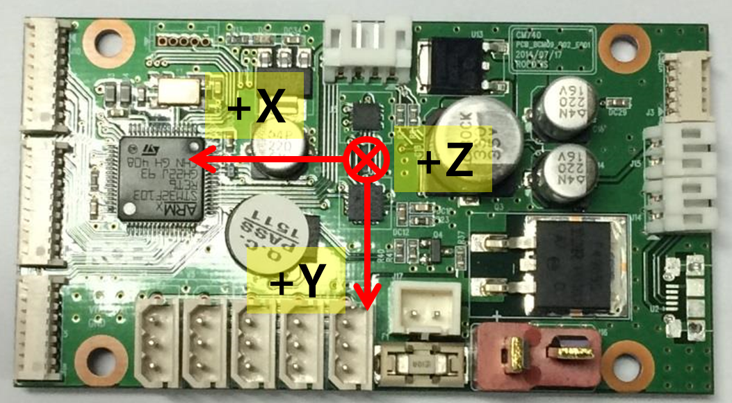
Accelerometer
 |
 |
|---|---|
| The Gyroscope axis in the ROBOTIS-OP2 | The Accelerometer axis in ROBOTIS-OP2 |
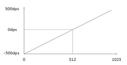
GYRO_X, GYRO_Y, GYRO_Z
They represent the angular velocity values of X-axis, Y-axis, Z-axis respectively.
The observable maximum velocity is -500DPS ~ 500DPS.
The following graph shows the process that angular velocity represents to value in reality.
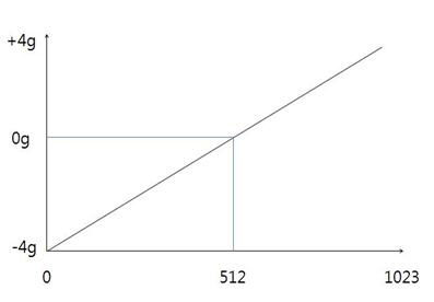
ACC_X, ACC_Y, ACC_Z
They represent the acceleration values of X-axis, Y-axis, Z-axis respectively.
The observable maximum velocity is -4g ~ +4g.
The following graph shows the process that acceleration represents to value in reality.
PRESENT VOLTAGE
Present (input) voltage.
This value is 10 times larger than the actual voltage. For example, when 10V is supplied, the data value is 100 (0x64)
MIC 1 , MIC 2
They are the wave values of MIC on the ears at HEAD PCB.
It is the value of ADC, and its range is 0~1023.
ADC 2 ~ ADC15
They are ADC values of ADC channel connected external port(J8).
CM-740 has ADC of 10BIT RESOLUTION.
Its range is 0 ~ 1,023