
Introduction
What is a Motion?
A motion is a set of actuator position and speed data necessary for robot movements.
In order for the robot to move, a motion file is required. A suitable motion file must be downloaded for the assembled robot.
A motion file is identified by the icon below, and its file extension is .mtn.

What is the relationship between a motion and task code?
A task code file is a program while a motion file is data. For better understanding, let us think about MP3 players and MP3 files. If there were no MP3 players, you will not be able to listen to music because MP3 file could not be played. The result is the same when there is an MP3 player but no MP3 file. If you want to make your robot move, you need a task code file. If the task code downloaded into your robot uses motions, you must download the motion file as well. If no motions are used in the task code, you do not need the motion file.
NOTE : To use motions in a task code, the motion file must be downloaded.
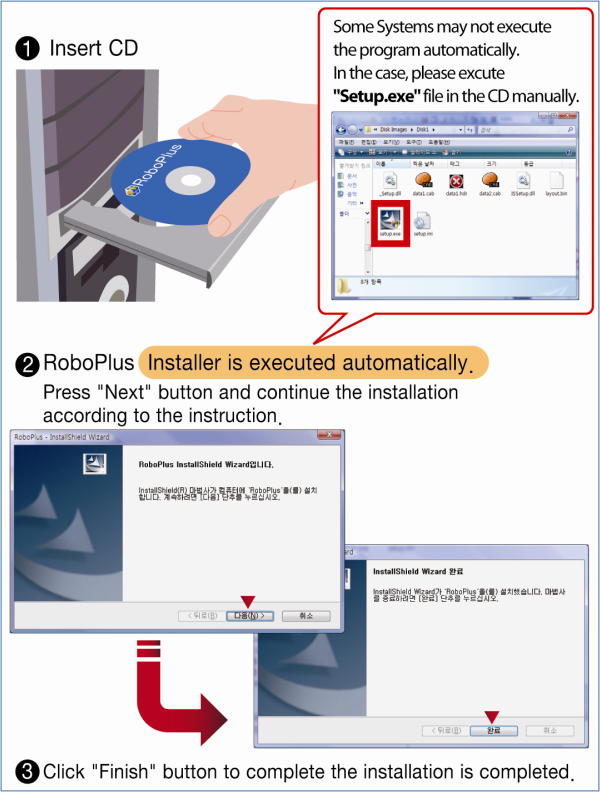
Install
Download RoboPlus
RoboPlus is a software to create a customized programme for every ROBOTIS product.
RoboPlus System Requirements
- OS : Windows XP Service Pack 2 or above / Vista/ 7 (32/64bit)/8 (32/64bit)
- 32bit(x86) or 64bit (x64) processor with over 800MHz
- Graphic card with 3D acceleration
- System memory over 512MB
- Hard disk with the extra space of 500MB
NOTE : To execute RoboPlus, .NET FrameWork 3.5 or higher version is required. When installing RoboPlus, if the automatic installation of .NET FrameWork fails, .NET FrameWork must be installed separately.
RoboPlus Install Failure
Most reason for installation failure is caused by .NET Framework install error. Please manually intsall Windows Installer 3.1 and .NET Framework 3.5
Windows installer and .NET Framework can be downloaded from Microsoft Download Center.
Download Windows installer 3.1, .NET Framework 3.5
Getting Started
Robot Motion
“Robot Motion” refers to the motion data in the controller.
These data can be seen and edited on the “Robot Motion” window.
This window is displayed only when the robot is connected.
(See how to Connect to Robot)

File Motion
“File Motion” refers to the motion data in the form of files in the PC.
These data can be seen and edited on the “File Motion” window.
Multiple “File Motion” windows can be displayed at once.
Connect to Robot
- Connect the robot to the PC (Please refer to Controller Information for details)
-
Select the communication port to use.
Choose the communication port to which the robot is connected. If you don’t know the port number, use the “Auto Searching” function.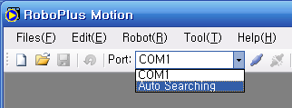
-
Connect with the robot. Choose the “Connect Robot” menu.
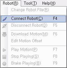
If you are unable to connect to the robot, please check following:
- Is the controller connected to the PC?
- Is the controller turned on?
- Was the correct port selected?
- Is the controller compatible with RoboPlus Motion?
- CM-100 is not compatible.
- CM-5 is compatible only after a firmware upgrade.
-
Disconnect the Robot.
To disconnect from the robot, choose the “Exit” menu or simply close the window.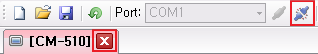
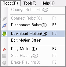
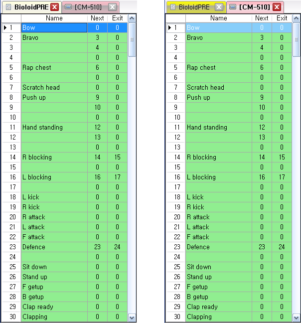
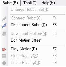
Download Motion
File motions can be converted into robot motions.
- Open the file motion to download.
- Connect to the robot.
-
Click on the “Download Motion” menu and wait for the download to complete.
-
Verify that the contents of the file motion have been copied to the robot motion as seen below.
- Download RoboPlus Program (for CM-510/530)
Play Motion
You can play the created motions. Search the page to play and click “Play Motion”.
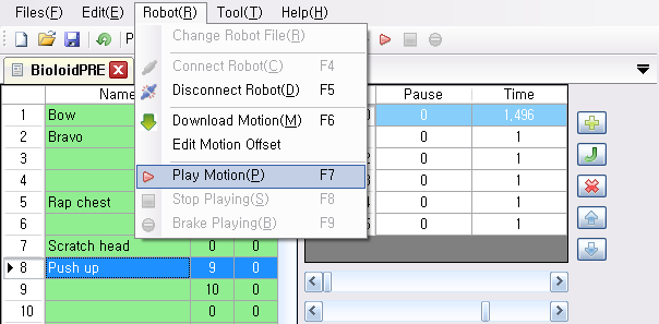
- Errors may occur when trying to play motions.
- This error can be seen while working on a “Robot Motion” window. In this case, the page linked as Next or Exit has been modified, but the controller does not have enough memory to temporarily save it.
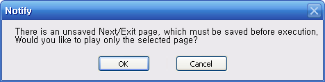
This can be solved by saving the page before execution. If you proceed without saving, only the current page will be played.
- This error can be seen while working on a “File Motion” window. In this case, the data in the PC is not the controller, and the controller does not have enough memory to temporarily save the Next or Exit page.
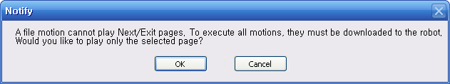
You can execute only the chosen page. To play linked pages, you must download the motion to the robot.
Stop Motion
Stops the motion that is being carried out.

“Stop Motion” does not stop execution right away. Instead, the “Exit” page is executed before stopping.
Emergency Stop
Stops the motion that is being carried out.

Unlike “Stop Motion,” “Emergency Stop” halts execution immediately.
Motion Editing
Things to be aware of before editing motions are introduced here.
Setting DYNAMIXEL ID
The motion player in the controller can control a total of 26 DYNAMIXEL’s (from ID 0 to 25). Therefore, to create a motion with RoboPlus Motion, the ID of each DYNAMIXEL must be between 0 and 25.
Control Priority
DYNAMIXEL’s may be controlled by both RoboPlus Motion and RoboPlus Task. Generally, the control priority is as follows:
- RoboPlus Motion (ID of DYNAMIXEL is between 0 and 25.)
- RoboPlus Task
In other words, once a motion is executed, DYNAMIXEL will be controlled by only RoboPlus Motion, and RoboPlus Task will have no control over the DYNAMIXEL. However, this control priority may be changed by users, if so desired.
There are 2 ways to change the control priority:
- In the motion data : Use ID Used/Not-Used function.
- In the task code : Use the Joint Offset Parameter. The advantage of this method is that the control priority may be changed according to the situation.
DYNAMIXEL Auto Shutdown Function
DYNAMIXEL’s have an Auto Shutdown function. This function prevents DYNAMIXEL’s from being damaged. The Auto Shutdown function will be triggered in the following situations.
- The motor has overheated due to an increase in internal temperature.
- The motor has been under too much load for an extensive period of time.
When the Auto Shutdown function is triggered, the following will be seen.
- The DYNAMIXEL LED will blink.
- The motor will stop moving, resulting in no torque.
To solve this problem, the following steps must be taken.
- Resolve what triggered the Auto Shutdown function.
- If the motor has overheated, let it cool with some rest.
- If the motor is under too much load, remove some of the load.
- Turn off DYNAMIXEL and turn it back on.
When creating a motion, the joint may not move. This is because the Auto Shutdown function has been triggered by the causes listed above.
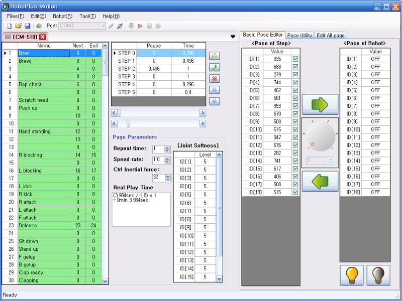
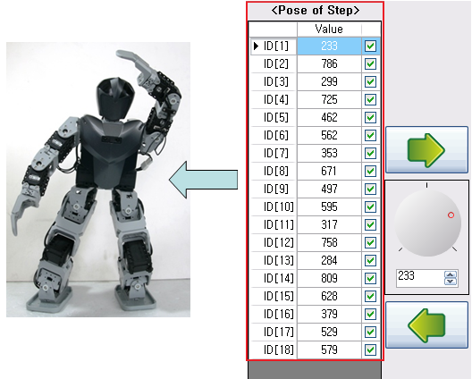
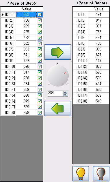
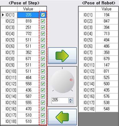
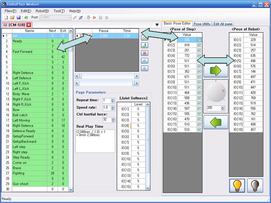
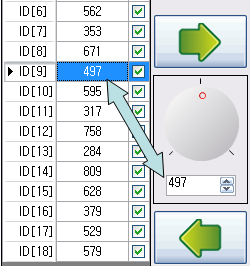
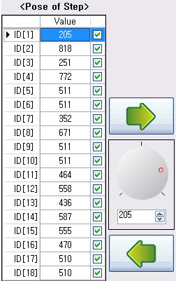
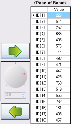
Pose Editing
A pose is the robot’s position at a point in time. It is a collection of motor position values required for the posture.
-
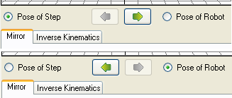
Pose of Steprefers to the data values of the pose. -
Pose of Robotrefers to the position values of the connected robot’s joints. When the Pose of Robot is modified, the robot will move accordingly.
Basic Pose Editing
The Basic Pose Editor is a simple editor that may be used for any type of robot. To change the number of ID’s used at “Pose of Step,” use the ID Editing Function.
Select Actuator ID
Click on a row to select an actuator. The following methods may be used to select multiple actuators.
-
To select actuators in consecutive order.
- Drag with mouse.
- Select actuators while holding down the “Shift” key.
-
To select actuators separately.
- Select actuators while holding down the “Ctrl” key.
-
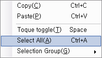
To select all actuators.
-
Press the button in the upper left corner.
-
Click on the “Select All” menu.
-
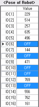
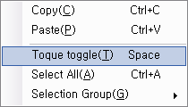
Torque On/Off
The “Torque On/Off” function enables you to make a pose manually by turning the robot’s joints on or off.
This function is only available in “Pose of Robot.”
If the torque is on, its position value will be shown. Otherwise, the value will be displayed as ‘OFF’.
The torque may be turned on or off through the following methods.
-
Press the “On” button to turn on the selected actuator.

-
Press the “Off” button to turn off the selected actuator.

-
Click the “Torque Toggle” menu to turn it off when it is on and to turn it on when it is off.
Change Actuator Value
The position value of the selected actuator may be changed after choosing the joint in “Pose”.
Play Pose
To execute a pose, move “Pose of Step” to “Pose of Robot.”

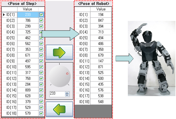
Capture Pose
To “Capture”(Store) a pose, move “Pose of Robot” to “Pose of Step.”


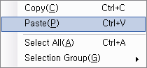
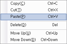
Copy/Paste Pose
These functions enable the actuator values to be changed easily.
Not only can poses be copied and pasted within the program, but texts from other files, such as Microsoft Excel, may be copied.
(When copying text from another program, values are delimited by spaces, new lines and tabs.)
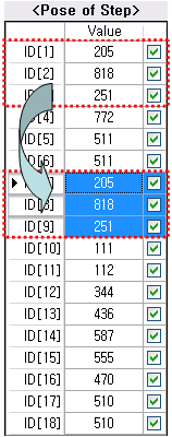
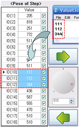
-
Copy Pose: Click on “Copy” or press Ctrl+C.
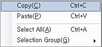
-
Paste Pose: Click on “Paste” or press Ctrl+V.
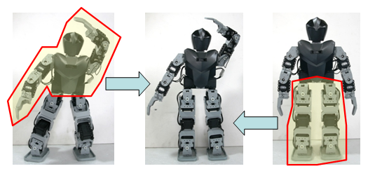
Mask Pose
Masking a pose refers to the process of making a new pose by combining 2 poses by setting whether the value is used or not while executing or capturing a pose.
For example, Pose C may be created by adding the upper body of Pose A with the lower body of Pose B.
Pose Utility
The pose utility is a tool to easily create a pose based on previously supplied information.
- 3D robot control : A pose can be created by moving the 3D robot’s joints.
- Mirror: A symmetrical pose can be created or the pose can be reversed.
- Inverse Kinematics: The accurate positions of each joint can be calculated.
NOTE :
- Information regarding the robot are required to create a pose using the pose utility. Therefore, a robot not on the list cannot be used.
- Some robots may not support the functions listed above.
- Because the pose utility uses 3D graphics, its performance depends on your graphic card.
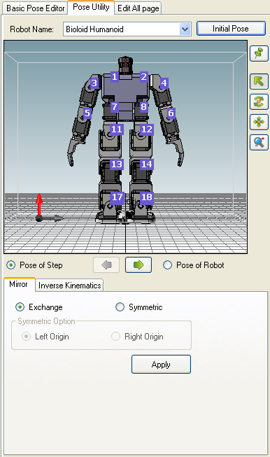
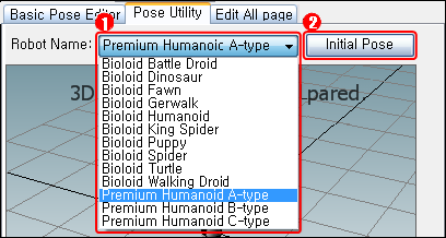
Select Robot
Before using the pose utility, you must first select the robot. Click the robot’s name on the list below to select an applicable robot.
NOTE : Pose utility cannot be used on a robot not on the list. In case of a user’s robot, the motions of the robot must be created by Basic Pose Editor.

- Select the name of robot to create a pose for.
| Robot Name | Description |
|---|---|
| Bioloid Battle Droid | Battle Droid Robot from Bioloid Intermediate Example. |
| Bioloid Dinosaur | Dinosaur Robot from Bioloid Advanced Example. |
| Bioloid Fawn | Baby Fawn Robot from Bioloid Intermediate Example. |
| Bioloid Gerwalk | Gerwalk Robot from Bioloid Advanced Example. |
| Bioloid Humanoid | Humanoid from Bioloid Advanced Exampe. |
| Bioloid King | Spider King Spider Robot from Bioloid Advanced Example |
| Bioloid Puppy | Puppy Robot from Bioloid Advanced Example |
| Bioloid Spider | Spider Robot from Bioloid Intermediate Example |
| Bioloid Turtle | Turtle Robot from Bioloid Intermediate Example |
| Bioloid Walking | Droid Walking Droid Robot from Bioloid Beginner Example |
| Premium Humanoid | A-type Bioloid Premium Humanoid |
| Premium Humanoid | B-type Bioloid Premium Humanoid |
| Premium Humanoid | C-type Bioloid Premium Humanoid |
- When the “Initial Pose” button is pressed, the robot will assume its initial position.
Control 3D Robot
Control View
3D robot can be seen from various angle using the view control function.

- Zoom Fit : The view angle is reset to the initial status.
- Select Objects : The joints can be selected by the mouse cursor.
- Rotate the View : The view can be rotated using the mouse. The same thing as above occurs when you press the wheel button of mouse and move.
- Move the View : The view can be moved horizontally using the mouse. The same thing as above occurs when you press the wheel button of mouse and move, while pressing “Ctrl” key.
- Increase/Decrease the View : The view can be increased or decreased using the mouse. The same thing as above occurs when you spin the mouse wheel.
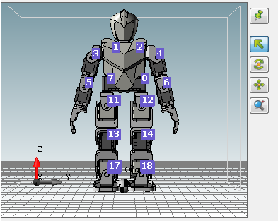
Control Joints
The number appeared on the robot are the ID of DYNAMIXEL. If you place your mouse on the ID, the color of choosable DYNAMIXEL is changed.
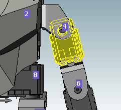
If you click the relevant joint, the joint value appears. The joint value is appeared as angle, not the motor value.
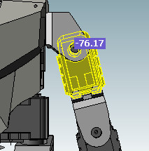
If you move the mouse to left and right while pressing the left botton of the mouse, the value increases or decreases.
In case of 1,024-based control, the unit of the value is approximately 0.29(300 / 1,024), and in case of 4,096-base, it is approximately 0.06(250.92 / 4,096).
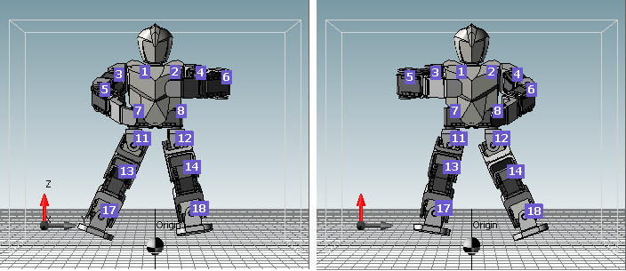
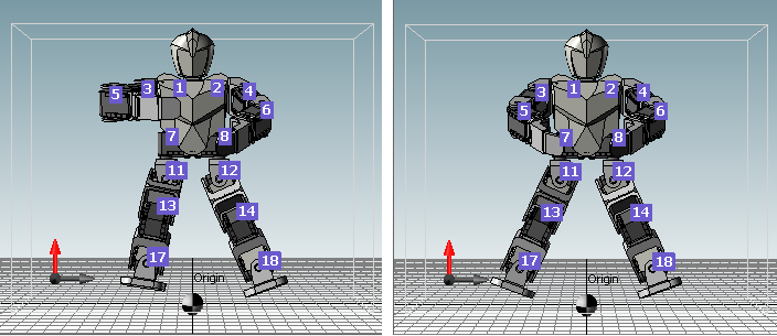
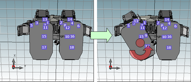
Mirror
The mirror function provides two functions: “exchange” and “symmetric.” Press “Apply” after choosing the function to apply it to your robot.
-
Exchange
The robot’s left side and right side are reversed to create a mirror image of the previous pose.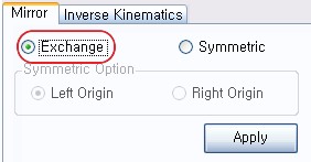
-
Symmetry
A symmetric pose based on the selected side is created.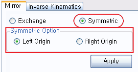
Inverse Kinematics
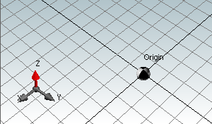
Position and Coordinate System
Understanding the kinematics of the robot’s movements starts with figuring out where each robot part is located. We must first assign a coordinate point as the origin, and then mark the displacement of each part on the coordinate system.
Coordinates axis and origin on the View are shown as below, and the unit of the grid is 20mm.
Here, Origin means that the coordinates of X, Y, Z is (0, 0, 0).
Kinematics and Inverse Kinematics
Kinematics is used to determine the location or movement of the end point from the angle or movement of the joint. In other words, kinematics allows us to determine where the end points once the joint values have been decided. For example, suppose there is a manipulator with two joints in the same plane as shown below. Using the angles of the joints, the coordinate (x,y) of the end point can be determined through kinematics. Kinematics results in only one solution.
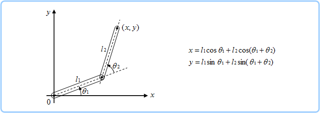
On the other hand, inverse kinematics may be used to determine the angle or movement of the joint from the location or movement of the end point. For example, suppose again that there is a manipulator with two joints in the same plane coordinates. If the end point (x,y) has been determined, there are 2 possible values for each joint as seen below.
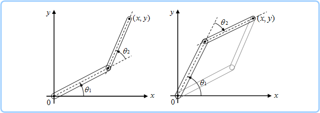
When using inverse kinematics, the coordinate (x,y) of the end point may be located at an unreachable distance from the origin or no solution may be obtained due to limitations on joint angles. If more joints are used, there may be infinitely many solutions.
End Point Control
When the user selects how much and in which direction to move the end point, the “Inverse Kinematics” function in the pose utility will calculate the values of each joint and move the end point automatically.
This function needs a module executes “Inverse Kinematics” calculation. Currently, the robots support “Inverse Kinematics” calculation are as follows:
- Bioloid Humanoid
- Bioloid Premium Humanoid Type A
- Bioloid Premium Humanoid Type B
- Bioloid Premium Humanoid Type C
This subject is explained on the basis of Bioloid Premium Humanoid Type A.
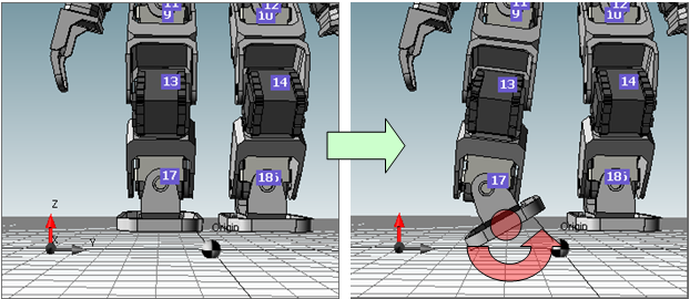
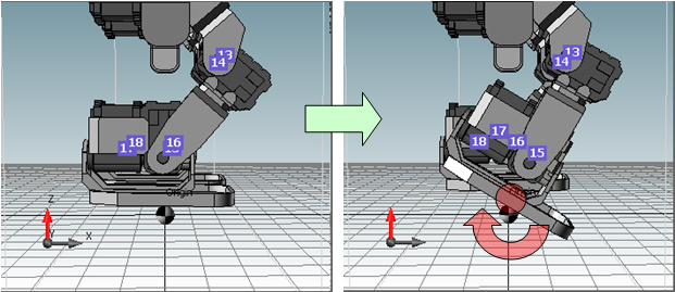
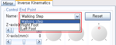
Select the end point
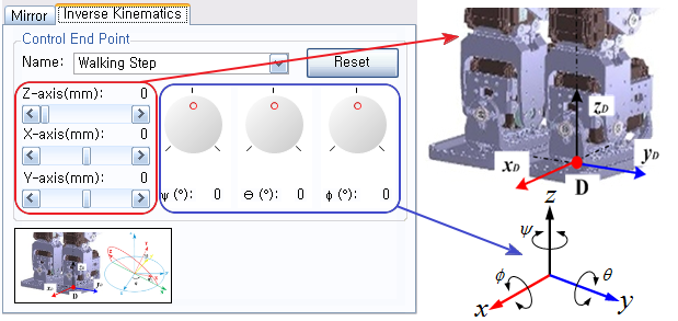
- Walking Step : Located at the middle of both feet, used to move both feet.
- Right Foot : Located at the center of the right foot, used to move only the right foot.
-
Left Foot : Located at the center of the left foot, used to move only the left foot.

Initialize the end point
The location of the end point is initialized.
Move the end point
The end point in 3D space can be controlled by 6 parameters. Depending on the structure of robots, all the 6 paramters may not be appeared.
To change the values, select relevant parameters, and then use the following methods.
- Press the
[or]to increase or decrease the value by 1. - Press the
[or]while pressingShiftto increase or decrease the value by 10. -
The controller can change the values appears if you double-click or press
Enter.
-
X(mm): it is moved to the X-axis diretion by the unit of mm.
-
Y(mm): it is moved to the Y-axis direction by the unit of mm.
-
Z(mm): it is moved to the Z-axis direction by the unit of mm.
-
φ(°): it is rotated based on the X-axis by the unit of angle.
-
θ(°): it is rotated based on the Y-axis by the unit of angle.
-
ψ(°): it is rotated based on the Z-axis by the unit of angle.
Since each paramater has its minimum and maximum values, it can be changed only in the range.
Sometimes, mathematical results cannot be obtained by inverse kinematics calculation, so the situation is called “no solutions” or “Infinite solutions.” Due to the such fact, the parameter values are not changed despite they are located in the range. In that case, the solution can be obtained if other parameter values are replaced.
(For instance, in case that the legs are straightened until the end (z=0), X or Y parameter is not changed.)
Apply the Result
When Pose of Step is selected, the pose values on the data are changed, and if Pose of Robot is selected, the pose values of robot are changed.
Pose Execution/Capture
Pose of Step and Pose of Robot
Pose of Step means the steps on the `currently selected motion file. That is, the pose changed in pose utility is reflected to the motion file immediately, while Pose of Step has been selected.
NOTE : Pose of Step is activated only when there are steps on the currently selected page. Pose of Robot is activated only when the robot is connected.
Pose Execution/Capture
It is the same function as Play Pose, Capture Pose of the Basic Pose Editor.
- Pose Execution: Pose of Step is reflected to Pose of Robot.
- Pose Capture : Pose of Robot is reflected to currently selected Pose of Step.
Step Editing
A “Motion Step” means by key frames, that are required to play consecutive motions.
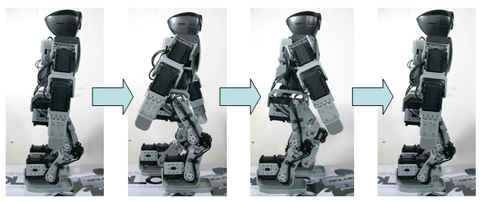
The speed of a motion is determined by the time of each step.
The step editor enables steps to be edited easily.

Each page consists of a maximum of 7 steps.
To make a motion with more than 7 steps, you will need to connect pages.
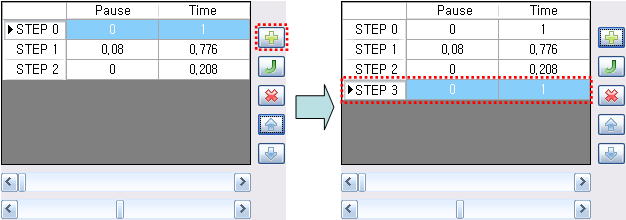
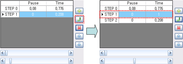
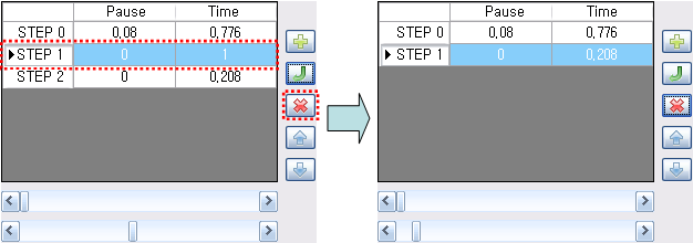
Add/Insert/Delete/Move Step
Add Step
A new step is added at the bottom of the step list.
Insert Step
A new step is inserted above the selected step.
Delete Step
The selected step is deleted from the list.
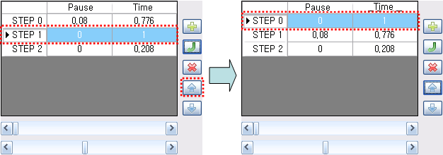
Move Step
The selected step may be moved up or down.
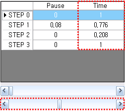
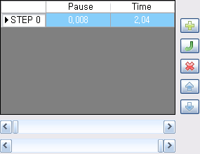
Pause
- “Pause” is the time between the end of the current step and the start of the next step.
- The unit of the value is seconds, and the value can be changed in 0.008 increments.
- The value is between 0 and 2.04 seconds.
-
The value can be changed using the upper scroll bar.
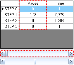
Time
- “Time” is the time between the time from the start of the current step to the end of the current step.
- The unit of the value is seconds, and the value can be changed in 0.008 increments.
- The value is between 0.072 and 2.04 seconds.
-
The value can be changed using the lower scroll bar.
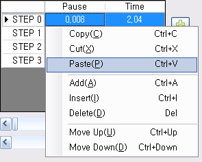
Copy/Cut/Paste Step
Copy Step
The selected step is copied.
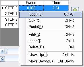
Cut Step
The selected step is cut.
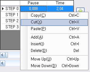
Paste Step
The copied or cut step is pasted. The value in the selected step is overwritten.
Page Editing
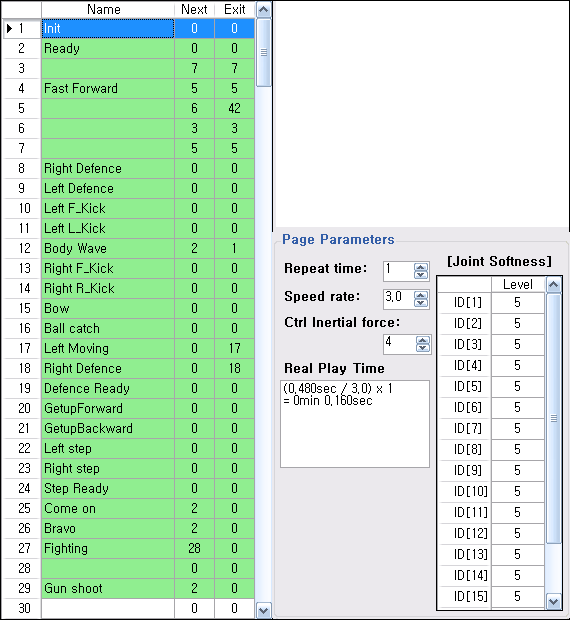
“Motion page” is the unit used to distinguish between saved motions.
Imported motions are read in terms of pages.
Motion data consists of 255 pages. (Some controllers are limited to only 127 pages.)
Select Page
Click on a row to select a page. The following methods may be used to select multiple pages.
-
To choose pages in consecutive order
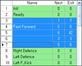
- Drag with mouse
- Choose pages while holding down the “Shift” key.
-
To choose pages separately
- Choose pages while holding down the “Ctrl” key.
-
To choose all pages
-
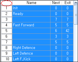
Press the button in the upper left corner
-
Connect Page
Pages can be connected to each other if necessary.
NOTE : When data is exchanged using the Copy/Cut/Paste functions, page connection information is not exchanged.
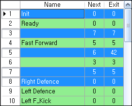
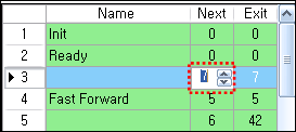
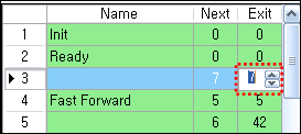
Next Page
A single page can have a maximum of 7 steps. Therefore, some motions may not fit in one page. To use multiple pages for one motion, designate the page to link to.
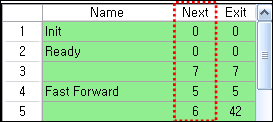
Enter the number of the next page in the “Next” column.
Exit Page
When commands are made to stop a motion, the robot will usually be in a highly unstable state due to the motion being executed. To stop a motion in a stable state, designate an exit page.
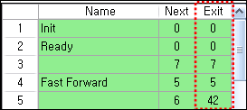
Enter the number of the exit page in the “Exit” column.
Copy/Cut/Paste Page
Copy Page
The selected page is copied.
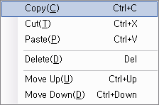
Cut Page
The selected page is cut.
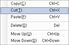
Paste page
The copied or cut page is pasted. The contents of selected page is overwritten.
Set Page Repeat/Time
Repeat Time
This is the number of times the current page is repeated during motion execution.
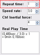
Speed Rate
- This is the playback speed of the page during motion execution. Unlike “Step Time,” this applies to the entire page.
- If the speed rate is 1.0, the page will be executed at normal speed.
- If the speed rate is lower than 1.0, the execution speed will decrease.
- If the speed rate is higher than 1.0, the execution speed will increase.
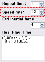
Inertial Force Control
Force is generated between steps. We call this force “inertial force,” because it is the result of the law of inertia. In general, inertial forces are created by acceleration, which is the change in speed. That is, as acceleration increases, inertial force also increases, and as acceleration decreases, inertial force also decreases. To reduce acceleration, increase or decrease the speed gradually, and to increase acceleration, change the speed drastically .”Ctrl Inertial Force” is used to control this acceleration. Increase this value to increase or decrease the speed gradually, reducing the acceleration.
-
The value is between 0 and 127. (Default is 32.)
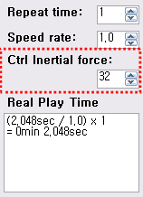
- The closer the value is to 0, the greater the inertial force.
- The closer the value is to 127, the lower the inertial force.
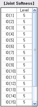
Joint Softness
Joint softness is used to set the compliance of DYNAMIXEL. The pros and cons of different joint softness values are as follows:
- When the joint softness is big
- Pro: Movement is smooth. Used for fluid movements, such as dancing.
- Con : May not be good for legs that need much support.
- When the joint softness is small
- Pro: Movement is stable. Used for movements that require support, such as walking.
- Con: Movement may look too rigid when performing fluid motions.
There are 7 joint softness levels.
- Level 1: Almost none (Not recommended)
- Level 2: Very Low
- Level 3: Low
- Level 4: Somewhat Low
- Level 5: Average (Default)
- Level 6: High
-
Level 7: Very High
More Information
Upload Robot Motion
Transferring motion data from the controller to the PC is called “uploading.”
-
Connect the robot to the PC to see the Robot Motion window.

-
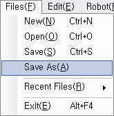
After selecting the Robot Motion window, click on “Save As”.
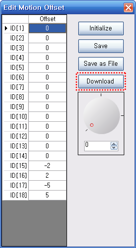
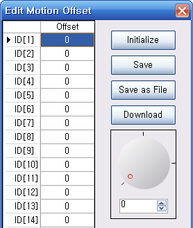
Motion Offset
Offset is the difference from a standard value. Motion offset refers to the difference from the standard motion, and the robot that performs the standard motion is called the “Master Robot”.
Even when robots of the same type are performing the same motions, there will be differences in their poses. This is due to discrepancies in motor locations and errors in assembly. These differences may even cause some robots to fall down. “Motion Offset” is used to resolve these differences.
NOTE : Generally, motion offset is small enough to be ignored. However, for robots that are sensitive to balance, such as humanoids, motion offset can be a source of critical problems.
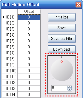
Edit Motion Offset
Discrepancies in the location of robot joints can be fixed using the “Edit Motion Offset” function.
When the menu is selected, the torque of all joints will be turned on to sustain its current position. Therefore, it would be beneficial to execute this function when the robot is in a pose where the differences can be easily distinguished.
Select the joint to edit its value with the editor.
- Positive values indicate movement in the CCW direction.
-
Negative values indicate movement in the CW direction.
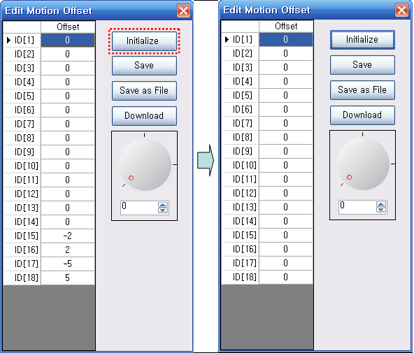
Initialize
Initiaizes all values to 0.
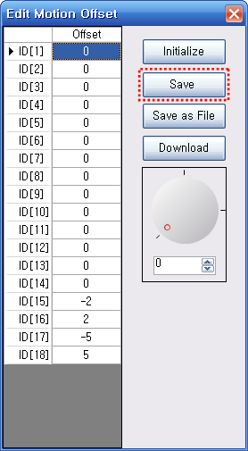
Save
Saves the current offset values. The values are saved in the controller.
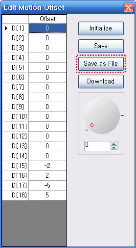
Save as File
Saves the robot’s current offset values as a file in the PC. The file extension of motion offset files is .ofs.
Download
Motion Offset files(*.ofs) in the PC can be downloaded to the robot.
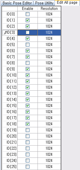
Edit All Page
“Edit All Page” is used to duplicate revisions on all pages. This function is required in the following situations:
- To change all motor values simultaneously Changes the value of every motor at once.
- To change ID usage status (whether it is being used or not)
Set Resolution
- The monitor’s resolution can be set.
- For the MX and EX series, please set the resolution value as 4096. For other DYNAMIXEL’s, 1024 is the recommended value.
- EX series have position control of 250 degrees.
- MX series have position control of 360 degrees.
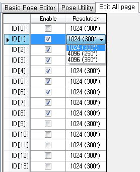
- When the resolution value is set as 4,096, the default values in the basic pose editor will be automatically changed from 512 to 2,048.
Set ID Usage Status
- RoboPlus Motion can handle the motions of robots with up to 26 motors. (DYNAMIXEL ID between 0 and 25). Set whether an ID is being used to edit only the necessary ID’s.
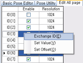
Exchange ID
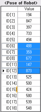
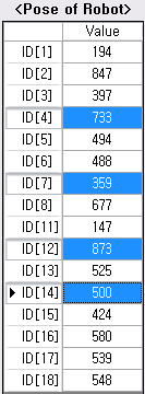
The position values of the robot’s joints can be easily exchanged. Select the 2 ID’s to exchange, and then click “Exchange ID.”
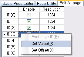
Change All Values
Use this function to change the value of the selected ID.
Apply Offset Values to All
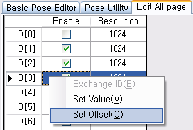
Offset is the difference from a standard value. Use this function to add or subtract a value from all joints with the selected ID.
Keyboard Shortcuts
When creating robot motions, it is difficult to use the mouse and keyboard at the same time, while holding the robot with one hand. Here, we introduce useful tips to make motions using only the keyboard.
Use arrow keys to move within the program
Arrow keys can be used to move the focus between the Page Edit Window, Step Edit Window, and Pose Edit Window.
Change the Joint Values
- Press the
[or]keys to increase or decrease the joint value by 1. - Press the
{or}keys (Shift+[or]) to increase or decrease the joint value by 10. - Press
Enterto move the focus to the setting window. When you are done changing the value, pressEnteragain to return the focus.
This function is available in the following windows:
-
Pose of Step
-
Pose of Robot
-
Edit Motion Offset
-
3D drawing of robot

Turn the torque on/off
After selecting the joint, press the space bar to turn the torque on or off.
Moving robot according to each step
Please choose the step that you want and press the enter key. Your robot will take the pose of selected step. (This is available only at robot motion window )
Making Robots
Users can make and operate their own robots usig RoboPlus Motion
WARNING : For this section, some previous knowledge on the following is required.
- XML
- 3D Graphics
- C# Programming
Folder Structure
If you look at the folder inside RoboPlus Motion, there are robot information file as shown below. (i.e, C:/Program Files/ROBOTIS/RoboPlus/Motion)
/Robots: There are files on robot’s information./Models: There are 3D model data for each part/PlugIn: There are IK(Inverse Kinematics) calculation modules.
In order for users to make their own robot, they need to make their own files and put them into folders accordingly
Robot Information File
Robot Infromation file has all the information required for the use of RoboPlus Motion.
This file has extension of .rbt. Robot list in “Pose Utility” tab shows the .rbt file list of various robots showed in the e-manual.
Robot Information file is written in the format of XML. Users can read the files using Windows TextPad.
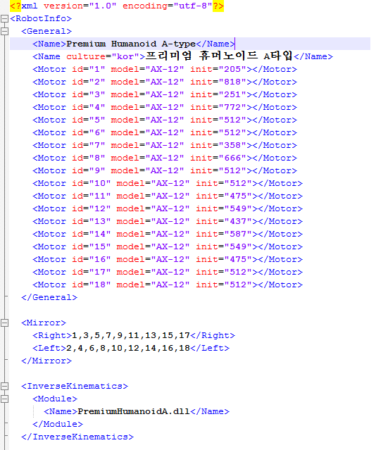
<General>
In this part, general information on the robot users making must be recorded.
<Name>
Put in the name that will be shown on the robot list.
You can give different “culture” values to show different languages (only for languages supported by RoboPlus Motion)
| Value | Language |
|---|---|
| kor | Korean |
| jpn | Japanese |
| N/A | English or any other languages |
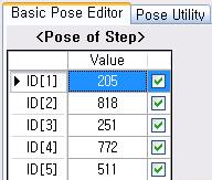
<Name>Premium Humanoid A-type</Name>
<Name culture=”kor”> Bioloid Premium Type A</Name>
Example of Bioloid Premium Type A
<Motor>
Input information for DYNAMIXEL’s used in robots.
- id: DYNAMIXEL ID
- model: model type
- init: position value for when “Initial Pose” button is pressed
<Motor id="1" model="AX-12+" init="205"></Motor>
<Motor id="2" model="AX-12+" init="818"></Motor>
<Motor id="3" model="AX-12+" init="251"></Motor>
<Motor id="4" model="AX-12+" init="772"></Motor>
<Motor id="5" model="AX-12+" init="512"></Motor>
<Motor id="6" model="AX-12+" init="512"></Motor>
<Motor id="7" model="AX-12+" init="358"></Motor>
<Motor id="8" model="AX-12+" init="666"></Motor>
<Motor id="9" model="AX-12+" init="512"></Motor>
<Motor id="10" model="AX-12+" init="512"></Motor>
<Motor id="11" model="AX-12+" init="475"></Motor>
<Motor id="12" model="AX-12+" init="549"></Motor>
<Motor id="13" model="AX-12+" init="437"></Motor>
<Motor id="14" model="AX-12+" init="587"></Motor>
<Motor id="15" model="AX-12+" init="549"></Motor>
<Motor id="16" model="AX-12+" init="475"></Motor>
<Motor id="17" model="AX-12+" init="512"></Motor>
<Motor id="18" model="AX-12+" init="512"></Motor>
Example of Bioloid Premium Type A
<Mirror>
Infromation needed for Mirror function. Not necessary if the function is not in use.

Only use for DYNAMIXEL’s in symmetric positions. If there is no symmetrically positioned Dynamixles, do not input anything.
- Right: DYNAMIXEL IDs for devices on the right side
- Left: DYNAMIXEL IDs for devices on the left side
<Mirror>
   <Right>1,3,5,9,11,13,15,17</Right>
   <Left>2,4,6,10,12,14,16,18</Left>
</Mirror>
Example of Bioloid Premium Type A
<InverseKinematics>
This connects the modules for Inverse Kinematics computing. Computing modules are in the form of DDL. To learn how to make modules, please refer to Plug-In SDK Programming in the next section. If not using Inverse Kinematis, this section can be ignored.
<InverseKinematics>
   <Module>
      <Name>PremiumHumanoidA.dll</Name>
   </Module>
</InverseKinematics>
Example of Bioloid Premium Type A
<Object3D>
In this section, robot assembly information is included for 3D display. The robot assembly information is in the Tree structure. If 3D display not needed, this section can be ignored.
<Part>
In this section, each part’s information is included. The relationship between parts are expressed through the Tree structure.
- name: 3D Model name. There is no need to include extensions.
(i.e., for f3.igs, just put f3) -
T: 3x4 matrix that contains movement and rotation information for 3D display.
Each element is separated by space.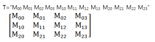
- id: Input ID number for DYNAMIXEL’s.
- type: Define what type of motor a part is.
-
If the whole body moves, define the motor’s type as “body.” (Horn is fixed in this case)
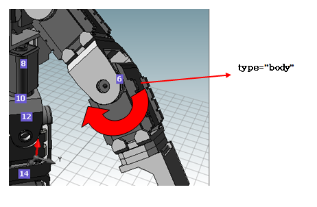
-
If the motor’s body is fixed and only its horn moves, define “body” to the part you want to fix and define “horn” to the part you want it to move.
-
<Object3D>
    <Part name="f51" T="0 0 1 0 1 0 0 0 0 1 0 302.5">
      <Part name ="f3" T="1 0 0 0 0 0 1 -70.5 0 -1 0 19"></Part>
      <Part name ="f3" T="1 0 0 0 0 0 -1 -70.5 0 1 0 -19"></Part>
      <Part name="f52" T="1 0 0 0 0 1 0 0 0 0 1 0">
Example of Bioloid Premium Type A
3D Model Data
Shown below are the 3D models of parts. These parts can be generated by various Computer Aided Design softwares. Users can add the parts created on their own in addition to the provided parts by ROBOTIS.
RoboPlus Motion only supports IGES(*.igs) format. ROBOTIS recommends to make data files small since if the data is too big, it will slow down the 3D display.
The following are the basic parts provided with RoboPlus.
| Name | Diagram | File |
|---|---|---|
| F1 |  |
f1.igs |
| F2 |  |
f2.igs |
| F3 |  |
f3.igs |
| F4 | 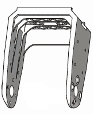 |
f4.igs |
| F5 | 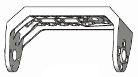 |
f5.igs |
| F6 |  |
f6.igs |
| F7 |  |
f7.igs |
| F8 |  |
f8.igs |
| F9 |  |
f9.igs |
| F10 |  |
f10.igs |
| F11 | 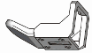 |
f11.igs |
| F12 | 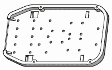 |
f12.igs |
| F15 + F16 |  |
f15.igs |
| F51 |  |
f51.igs |
| F52 |  |
f52.igs |
| F53 |  |
f53.igs |
| F56 |  |
f56.igs |
| F57 |  |
f57.igs |
| F58 |  |
f58.igs |
| F60 |  |
f60.igs |
| WA |  |
wa,igs |
| BU |  |
bu.igs |
| CM-5 |  |
cm-5.igs |
| ADAPTOR-CM5 |  |
adaptor_cm5.igs |
| BATTERY |  |
battery.igs |
| AX-12 |  |
ax-12.igs |
| AX-12 Horn |  |
ax-12_horn.igs |
| AX-S1 |  |
ax-s1.igs |
Plug-In SDK
Users can use Plug-In SDK to add inverse kinematics computing module from “Pose Utility.” Instruction is given using an example of developing C# from Visual Studio 2005. (Sample example included)
Download ZIPPlugInSDK_Example.zip
Create Project
Go to Visual Studio’s menu and select File > Create New > Project. Then select Visual C# > Windows > Classic Library to create a new project.
Add Reference
Go to Visual Studio’s menu and select Project > Add Reference. When a window box pops up, click “Find” then select Motion > PlugInSDK.dll in the folder Roboplus is installed.(i.e, C:\Program Files\ROBOTIS\RoboPlus\Motion\PlugInSDK.dll)
Implement Interface
Write command lines shown below in the Class file that is to be implemented. (i.e, Class1.cs)
using ROBOTIS.MotionEditor.SDK  // add namespace
namespace MyPlugIn
{
  public class MyPlugIn : IInverseKinematics // Interface succession
  {
  }
}
Put the mouse cursor on “IInverseKinematics” and right click it. Then select “Implement Interface -> Implement Interface” and sources will be automatically generated.
CurrentPose
It’s Pose data transferred from and received by RoboPlus Motion. Users must follow the rules shown below.
- Users create the arrangement of 26 pose data.
- The index of arrangement are the ID numbers of DYNAMIXEL’s.
- In order to deliever values to motors, put some number in between 0 ~ 1,023 or 4,096. If not, put -1.
When RoboPlus Motion is in “get” direction, inverse kinematics computing result should be delievered and when it is in “set” direction, endpoints should be calculated and computed using forward kinematics and based on Pose data.
EndPoints
This is the name to be printed on endpoint list.

Users can either choose one form the endpoint list or run the interface shown below to see the result.
- SelectedIndex: Index of endpoint
- SelectedEndPoint: Name of endpoint
X, Y, Z, Roll, Pitch, Yaw
It’s the data of location of end points from the origin.
Users can set minimum and/or maximum using user DLL.
Roll signifies rotation in x-axis, Pitch is in y-axis, and Yaw z-axis.
- MinX, MinY, MinZ, MinRoll, MinPitch, MinYaw: Minimum values for endpoints.
- MaxX, MaxY, MaxZ, MaxRoll, MaxPitch, MaxYaw: Maximum values for endpoints.
- If the minimum and maximum values are set at the same value for an endpoint, such endpoint is considered as not in use and thus, does not show up on the list.
- X, Y, Z, Roll, Pitch, Yaw: position values of endpoints.
Reset
By clicking the “reset” button on RoboPlus Motion, users can default the position values of endpoints.

Add Plug-In
If successful with building the project, copy the DLL file to the “PlugIn” folder inside the RoboPlus Motion folder. (For example, C:\Program Files\ROBOTIS\RoboPlus\Motion\PlugIn)
In robot informational file (*.rbt), write DLL information that wil compute inverse kinematics.
<InverseKinematics>
   <Module>
      <Name>PremiumHumanoidA.dll</Name>
   </Module>
</InverseKinematics>
Example of Bioloid Premium Type A
Run RoboPlus Motion and check if the (new) robot is operating properly.