
Introduction
DYNAMIXEL servos utilize the DYNAMIXEL protocol for serial communications and control operations. This document serves as a reference for the specifications of 2.0 DYNAMIXEL Protocol communication.
DYNAMIXEL Protocol 2.0 communications are supported on the following servos:
Note: MX(2.0) is a special firmware for the DYNAMIXEL MX series providing support for DYNAMIXEL Protocol 2.0. MX(2.0) firmware can be uploaded to your servo using Firmware Recovery in DYNAMIXEL Wizard 2.0.
DYNAMIXEL Protocol 2.0 communications are supported by the following controllers:
TIP : See the DYNAMIXEL Protocol Compatibility Table for more information.
Packet
DYNAMIXELs communicate with their controllers using structured data packets in one of two types:
- Instruction Packets: Sent by the main controller to the DYNAMIXEL. These packets contain the instructions for the actuators.
- Status Packets: Sent by the DYNAMIXEL back to the main controller. These packets return information reported by the actuator.
ID
Each DYNAMIXEL servo is assigned a communication ID for identification over the DYNAMIXEL bus.
Each connected DYNAMIXEL must have a unique ID number. If DYNAMIXELs with the same ID are connected, packet collision and network problems will occur. To change a DYNAMIXEL’s ID, reference the DYNAMIXEL Control Table section on the DYNAMIXEL Wizard 2.0 eManual page.
NOTE: The default ID number for new DYNAMIXEL actuators is 1.
DYNAMIXEL Protocol
DYNAMIXEL servos utilize half-duplex 8 bit Asynchronous Serial Communication with 1 Stop bit, and no Parity.
Half Duplex
Half duplex UART is a serial communication protocol where both TxD and RxD cannot be used at the same time. This method is generally used when many devices need to be connected to a single bus. Since multiple devices are connected to the same bus, all the other devices need to be in input mode while one device is transmitting. The Main Controller that controls DYNAMIXEL actuators also controls the switch between input and output communications modes.
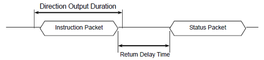
Tx, Rx Direction
For Half Duplex UART, the transmission ending timing is important to change the direction between sending and receiving mode. The bit definitions within the UART_STATUS register are as follows:
- TXD_BUFFER_READY_BIT: Indicates that the transmission DATA can be loaded into the Buffer. Note that this only means that the SERIAL TX BUFFER is empty, and does not necessarily mean that the all the data transmitted before has left the CPU.
- TXD_SHIFT_REGISTER_EMPTY_BIT: Set when all the Transmission Data has completed its transmission and left the CPU.
The TXD_BUFFER_READY_BIT is used when one byte is to be transmitted via the serial communication channel, and an example is shown below.
  TxDByte(byte bData)
  {
    while(!TXD_BUFFER_READY_BIT); //wait until data can be loaded.
    SerialTxDBuffer = bData; //data load to TxD buffer
  }
Before changing the communication direction, the TXD_SHIFT_REGISTER_EMPTY_BIT must be checked to ensure that all data has been transferred. The following is an example program that sends an Instruction Packet and waits until communciation has been completed before switching communication directions.
1  DIRECTION_PORT = TX_DIRECTION;
2  TxDByte(0xff);
3  TxDByte(0xff);
4  TxDByte(0xfd);
5  TxDByte(0x00);
6  TxDByte(bID);
7  TxDByte(bLengthLow);
8  TxDByte(bLengthHigh);
9  TxDByte(bInstruction);
10  TxDByte(Parameter0); TxDByte(Parameter1); ...
11  TxDByte(bCrcLow);
12  DisableInterrupt(); // interrupt should be disable
13  TxDByte(bCrcHigh);  // last TxD
14  while(!TXD_SHIFT_REGISTER_EMPTY_BIT); // Wait till last data bit has been sent
15  DIRECTION_PORT = RX_DIRECTION; // Direction change to RXD
16  EnableInterrupt(); // enable interrupt again
WARNING : Please note the lines between LINE 12 and LINE 16. Line 12 is necessary since an interrupt during data transmission may cause a delay longer than the return delay time and corruption to the status packet may occur.
Byte to Byte Time
The allowed delay time between bytes when sending an instruction packet is 1.5ms. If the delay time is over 1.5ms, then DYNAMIXEL actuator recognizes this as a communication problem and waits for the next header (0xff 0xff 0xfd) before continuing to process packets.

Instruction Packet
Instruction Packet is the command packet sent to provide instructions to the Device. The structure of the packet is as follows:
| Header 1 | Header 2 | Header 3 | Reserved | Packet ID | Length 1 | Length 2 | Instruction | Param | Param | Param | CRC 1 | CRC 2 |
|---|---|---|---|---|---|---|---|---|---|---|---|---|
| 0xFF | 0xFF | 0xFD | 0x00 | ID | Len_L | Len_H | Instruction | Param 1 | … | Param N | CRC_L | CRC_H |
Header
This field is used to indicate the start of a status packet.
Reserved
An additional 0x00 byte included in the header field.
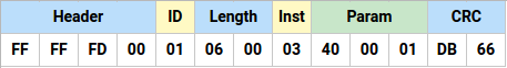
Example DYNAMIXEL packet
Packet ID
The field that indicates the ID of the device that should receive the Instruction Packet and process it.
- Range : 0 ~ 252 (0x00 ~ 0xFC), which is a total of 253 numbers that can be used.
- Broadcast ID : 254 (0xFE), which makes all connected devices execute the Instruction Packet.
WARNING: The DYNAMIXEL Broadcast ID (254 (0xFE)) will only return Status Packets for Ping, Sync Read and Bulk Read commands, other Instructions aside from Ping, Sync Read and Bulk Read will not return Status Packets when sent to the Broadcast ID.
Length
The field that specifies the full length of the transmitted packet, Divided into low and high bytes in the Instruction Packet. The Length includes the Byte size of Instruction, Parameters and CRC fields in the packet.
Length = the number of Parameters + 3- A returned Status Packet will also include a 1 byte length ERROR field in the data.
Instruction
The field that defines the type of command included in the instruction packet.
| Value | Instructions | Description |
|---|---|---|
| 0x01 | Ping | Instruction that checks whether the Packet has arrived at a device with the same ID as the specified packet ID |
| 0x02 | Read | Instruction to read data from the Device |
| 0x03 | Write | Instruction to write data to the Device |
| 0x04 | Reg Write | Instruction to register the Instruction Packet in standby status; Packet can later be executed using the Action command |
| 0x05 | Action | Instruction to executes a Packet that was registered beforehand using Reg Write |
| 0x06 | Factory Reset | Instruction that resets the Control Table to its initial factory default settings |
| 0x08 | Reboot | Instruction to reboot the Device |
| 0x10 | Clear | Instruction to reset certain information stored in memory |
| 0x20 | Control Table Backup | Instruction to store current Control Table status data to a Backup or to restore backup EEPROM data. |
| 0x55 | Status(Return) | Return packet sent following the execution of an Instruction Packet |
| 0x82 | Sync Read | Instruction to read data from multiple devices with the same Address with the same length at once |
| 0x83 | Sync Write | Instruction to write data to multiple devices with the same Address with the same length at once |
| 0x8A | Fast Sync Read | Instruction to read data from multiple devices with the same Address with the same length at once |
| 0x92 | Bulk Read | Instruction to read data from multiple devices with different Addresses with different lengths at once |
| 0x93 | Bulk Write | Instruction to write data to multiple devices with different Addresses with different lengths at once |
| 0x9A | Fast Bulk Read | Instruction to read data from multiple devices with different Addresses with different lengths at once |
Parameters
This section contains the data sent in the packet, and may differ in length and content depending on the type of packet sent.
WARNING: The method of expressing negative numbers in this data field may differ for each product. Please refer to the eManual page for your specific product for more information.
CRC
A 16bit checksum used to determine if the Packet has been damaged during communication. This field is divided into low and high bytes in the Instruction Packet and is calculated based on the content of the packet ranging from the Header (FF FF FD 00) to to the Parameters before the CRC field in the Instruction Packet. See the following page for CRC Calculation documentation.
Status Packet
The Status Packet is the response transmitted from the device to the main controller following the receipt of an Instruction Packet. Note that it has the same construction as the Instruction Packet with the addition of the ERROR field.
| Header 1 | Header 2 | Header 3 | Reserved | Packet ID | Length 1 | Length 2 | Instruction | ERR | PARAM | PARAM | PARAM | CRC 1 | CRC 2 |
|---|---|---|---|---|---|---|---|---|---|---|---|---|---|
| 0xFF | 0xFF | 0xFD | 0x00 | ID | Len_L | Len_H | Instruction | Error | Param 1 | … | Param N | CRC_L | CRC_H |
Instruction
The instruction for Status Packets is 0x55 (Status), this should be included as the instruction for all returned status packets.
Error
The field that indicates the result of the received Instruction Packet.
| Bit 7 | Bit 6 ~ Bit 0 |
|---|---|
| Alert | Error Number |
- Alert : When there is some hard ware issue with the Device, this field is set as 1. Checking the Hardware error status value of the Control Table can indicate the cause of the problem.
- Error Number : When there has been an Error in the processing of the Instruction Packet.
| Error Number | Error | Description |
|---|---|---|
| 0x01 | Result Fail | Failed to process the sent Instruction Packet |
| 0x02 | Instruction Error | An undefined Instruction has been used Action has been used without Reg Write |
| 0x03 | CRC Error | The CRC of the sent Packet does not match the expected value |
| 0x04 | Data Range Error | Data to be written to the specified Address is outside the range of the minimum/maximum value |
| 0x05 | Data Length Error | Attempted to write Data that is shorter than the required data length of the specified Address (ex: when you attempt to only use 2 bytes of a register that has been defined as 4 bytes) |
| 0x06 | Data Limit Error | Data to be written to the specified Address is outside of the configured Limit value |
| 0x07 | Access Error | Attempted to write a value to an Address that is Read Only or has not been defined Attempted to read a value from an Address that is Write Only or has not been defined Attempted to write a value to an EEPROM register while Torque was Enabled. |
Parameters
This section contains the data used as an argument to the instruction included in the packet, and may differ in length and content depending on the type of packet sent.
WARNING: The method of expressing negative numbers in this data field may differ for each product. Please refer to the eManual page for your specific product for more information.
Response Policy
The method of response to received Instructions can be modified using the value of the Status Return Level Control Table item. For more details, see the Status Return Level section of the eManual page for your specific actuator.
WARNING: The DYNAMIXEL Broadcast ID (254 (0xFE)) will only return Status Packets for Ping, Sync Read and Bulk Read commands, other Instructions aside from Ping, Sync Read and Bulk Read will not return Status Packets when sent to the Broadcast ID.
Packet Process
Transmission Process
- Generate basic packet structure including required parameters.
- Apply Byte Stuffing to ensure that packets are processed successfully.
- Update packet length to include any stuffed bytes.
- Calculate final CRC with byte stuffing applied.
NOTICE: Byte stuffing is a method of adding additional data to generated instruction packets to ensure that the packets are processed successfully. When the byte pattern “0xFF 0xFF 0xFD” appears in a packet, byte stuffing adds 0xFD to the end of the pattern to convert it to “0xFF 0xFF 0xFD 0xFD” to ensure that it is not interpreted as the header at the start of another packet.
Processing Order of Reception
- Search for packet Header (0xFF 0xFF 0xFD), ignoring any found Byte Stuffing (0xFF 0xFF 0xFD 0xFD).
- If the Packet ID is valid, prepare to receive additional transmission data the size of Length.
- Calculate the CRC with the received Packet with Byte Stuffing included, if the CRC matches, remove byte stuffing from received packet.
- Execute received packet.
Instruction Details
Note that given examples use the following abbreviations for each packet section:
- Header : H
- Reserved: RSRV
- Length: LEN
- Instruction: INST
- Error: ERR
- Param: P
Ping (0x01)
Description
- Used to check for the existence of a Device and retrieve basic information.
- Regardless of the Status Return Level of the Device a Status Packet will always be sent in response to a ping packet.
- When a Ping command is sent to the Broadcast ID - 0xFE all connected devices will respond with a status packet.
Packet Parameters
Note : A Status Packet will be received from each connected Device.
| Status Packet | Description |
|---|---|
| Parameter 1 | Model Number LSB |
| Parameter 2 | Model Number MSB |
| Parameter 3 | Version of Firmware |
Example 1
Conditions
- ID1(XM430-W210) : Model Number 1030(0x0406), Firmware Version 38(0x26)
- Instruction Packet ID : 1
Ping Instruction Packet
| H1 | H2 | H3 | RSRV | Packet ID | LEN1 | LEN2 | INST | CRC 1 | CRC 2 |
|---|---|---|---|---|---|---|---|---|---|
| 0xFF | 0xFF | 0xFD | 0x00 | 0x01 | 0x03 | 0x00 | 0x01 | 0x19 | 0x4E |
ID 1 Status Packet
| H1 | H2 | H3 | RSRV | Packet ID | LEN1 | LEN2 | INST | ERR | P1 | P2 | P3 | CRC 1 | CRC 2 |
|---|---|---|---|---|---|---|---|---|---|---|---|---|---|
| 0xFF | 0xFF | 0xFD | 0x00 | 0x01 | 0x07 | 0x00 | 0x55 | 0x00 | 0x06 | 0x04 | 0x26 | 0x65 | 0x5D |
Example 2
Conditions
- ID1(XM430-W210) : Model Number 1030(0x0406), Firmware Version 38(0x26)
- ID2(XM430-W210) : Model Number 1030(0x0406), Firmware Version 38(0x26)
- Instruction Packet ID : 254(Broadcast ID)
Ping Instruction Packet
| H1 | H2 | H3 | RSRV | Packet ID | LEN1 | LEN2 | INST | CRC 1 | CRC 2 |
|---|---|---|---|---|---|---|---|---|---|
| 0xFF | 0xFF | 0xFD | 0x00 | 0xFE | 0x03 | 0x00 | 0x01 | 0x31 | 0x42 |
ID 1 Status Packet
| H1 | H2 | H3 | RSRV | Packet ID | LEN1 | LEN2 | INST | ERR | P1 | P2 | P3 | CRC 1 | CRC 2 |
|---|---|---|---|---|---|---|---|---|---|---|---|---|---|
| 0xFF | 0xFF | 0xFD | 0x00 | 0x01 | 0x07 | 0x00 | 0x55 | 0x00 | 0x06 | 0x04 | 0x26 | 0x65 | 0x5D |
ID 2 Status Packet
| H1 | H2 | H3 | RSRV | Packet ID | LEN1 | LEN2 | INST | ERR | P1 | P2 | P3 | CRC 1 | CRC 2 |
|---|---|---|---|---|---|---|---|---|---|---|---|---|---|
| 0xFF | 0xFF | 0xFD | 0x00 | 0x02 | 0x07 | 0x00 | 0x55 | 0x00 | 0x06 | 0x04 | 0x26 | 0x6F | 0x6D |
Read (0x02)
Description
- Reads a specified value from the Control Table.
- Read Instructions are not executed when sent to the Broadcast ID(254 (0xFE))
WARNING: The method of expressing negative numbers data fields may differ for each product. Please refer to the eManual page for your specific product for more information.
Note: If the requested item is outside the range of the Control Table, the returned Status packet will include an Access Error in its error field, and return with with no parameters.
Packet Parameters
| Instruction Packet | Description |
|---|---|
| Parameter 1 | Low-order byte from the starting address |
| Parameter 2 | High-order byte from the starting address |
| Parameter 3 | Low-order byte from the data length (X) |
| Parameter 4 | High-order byte from the data length (X) |
| Status Packet | Description |
|---|---|
| Parameter 1 | First Byte |
| Parameter 2 | Second Byte |
| … | … |
| Parameter X | X-th Byte |
Example
Conditions
- ID1(XM430-W210) : Present Position(132, 0x0084, 4[byte]) = 166(0x000000A6)
Read Instruction Packet
| H1 | H2 | H3 | RSRV | Packet ID | LEN1 | LEN2 | INST | P1 | P2 | P3 | P4 | CRC 1 | CRC 2 |
|---|---|---|---|---|---|---|---|---|---|---|---|---|---|
| 0xFF | 0xFF | 0xFD | 0x00 | 0x01 | 0x07 | 0x00 | 0x02 | 0x84 | 0x00 | 0x04 | 0x00 | 0x1D | 0x15 |
ID 1 Status Packet
| H1 | H2 | H3 | RSRV | Packet ID | LEN1 | LEN2 | INST | ERR | P1 | P2 | P3 | P4 | CRC 1 | CRC 2 |
|---|---|---|---|---|---|---|---|---|---|---|---|---|---|---|
| 0xFF | 0xFF | 0xFD | 0x00 | 0x01 | 0x08 | 0x00 | 0x55 | 0x00 | 0xA6 | 0x00 | 0x00 | 0x00 | 0x8C | 0xC0 |
Write (0x03)
Description
- Instruction to write a value to the Control Table
WARNING: The method of expressing negative numbers data fields may differ for each product. Please refer to the eManual page for your specific product for more information.
Packet Parameters
| Instruction Packet | Description |
|---|---|
| Parameter 1 | Low-order byte from the starting address |
| Parameter 2 | High-order byte from the starting address |
| Parameter 2+1 | First Byte |
| Parameter 2+2 | Second Byte |
| … | … |
| Parameter 2+X | X-th Byte |
Example
Conditions
- ID1(XM430-W210) : Write 512(0x00000200) to Goal Position(116, 0x0074, 4[byte])
Write Instruction Packet
| H1 | H2 | H3 | RSRV | Packet ID | LEN1 | LEN2 | INST | P1 | P2 | P3 | P4 | P5 | P6 | CRC 1 | CRC 2 |
|---|---|---|---|---|---|---|---|---|---|---|---|---|---|---|---|
| 0xFF | 0xFF | 0xFD | 0x00 | 0x01 | 0x09 | 0x00 | 0x03 | 0x74 | 0x00 | 0x00 | 0x02 | 0x00 | 0x00 | 0xCA | 0x89 |
ID 1 Status Packet
| H1 | H2 | H3 | RSRV | Packet ID | LEN1 | LEN2 | INST | ERR | CRC 1 | CRC 2 |
|---|---|---|---|---|---|---|---|---|---|---|
| 0xFF | 0xFF | 0xFD | 0x00 | 0x01 | 0x04 | 0x00 | 0x55 | 0x00 | 0xA1 | 0x0C |
Reg Write (0x04)
Description
- Instruction similar to a Write Instruction, but with an improved synchronization characteristic. Write Instructions are executed immediately when an Instruction Packet is received, while Reg Write saves the command to be executed later in response to an Action instruction.
- By using Reg Write and Action Instructions, one can operate multiple devices simultaneously.
- Reg Write Instruction registers the Instruction Packet to a standby status, and sets Control table Registered Instruction to ‘1’.
- When an Action Instruction is received, the registered Packet is executed, and sets Control Table Registered Instruction to ‘0’.
Packet Parameters
| Instruction Packet | Description |
|---|---|
| Parameter 1 | Low-order byte from the starting address |
| Parameter 2 | High-order byte from the starting address |
| Parameter 2+1 | First Byte |
| Parameter 2+2 | Second Byte |
| … | … |
| Parameter 2+X | X-th Byte |
Example
Condition
- ID1(XM430-W210) : Write 200(0x000000C8) to Goal Velocity(104, 0x0068, 4[byte])
Reg Write Instruction Packet
| H1 | H2 | H3 | RSRV | Packet ID | LEN1 | LEN2 | INST | P1 | P2 | P3 | P4 | P5 | P6 | CRC 1 | CRC 2 |
|---|---|---|---|---|---|---|---|---|---|---|---|---|---|---|---|
| 0xFF | 0xFF | 0xFD | 0x00 | 0x01 | 0x09 | 0x00 | 0x04 | 0x68 | 0x00 | 0xC8 | 0x00 | 0x00 | 0x00 | 0xAE | 0x8E |
ID 1 Status Packet
| H1 | H2 | H3 | RSRV | Packet ID | LEN1 | LEN2 | INST | ERR | CRC 1 | CRC 2 |
|---|---|---|---|---|---|---|---|---|---|---|
| 0xFF | 0xFF | 0xFD | 0x00 | 0x01 | 0x04 | 0x00 | 0x55 | 0x00 | 0xA1 | 0x0C |
Action (0x05)
Description
- Instruction that executes the Packet that has been registered using Reg Write Instruction
- When controlling multiple devices using Write Instruction, there will be a difference in the time of execution between the first device that receives the Packet and the last device that receives the Packet.
- By using Reg Write and Action Instruction, one can operate multiple devices simultaneously.
Example
Condition
- ID1(XM430-W210) : Instruction has been already registered by the Reg Write Instruction.
Action Instruction Packet
| H1 | H2 | H3 | RSRV | Packet ID | LEN1 | LEN2 | INST | CRC 1 | CRC 2 |
|---|---|---|---|---|---|---|---|---|---|
| 0xFF | 0xFF | 0xFD | 0x00 | 0x01 | 0x03 | 0x00 | 0x05 | 0x02 | 0xCE |
ID 1 Status Packet
| H1 | H2 | H3 | RSRV | Packet ID | LEN1 | LEN2 | INST | ERR | CRC 1 | CRC 2 |
|---|---|---|---|---|---|---|---|---|---|---|
| 0xFF | 0xFF | 0xFD | 0x00 | 0x01 | 0x04 | 0x00 | 0x55 | 0x00 | 0xA1 | 0x0C |
Factory Reset (0x06)
Description
- Instruction that resets the Control Table to its initial factory default settings.
- When Factory Reset (0x06) Instruction is performed, the device is rebooted and the LED blinks four times in a row to indicate a successful reset.
WARNING: When the Packet ID is the Broadcast ID 0xFE and the configured Option is Reset All 0xFF, the Factory Reset Instruction(0x06) will NOT be executed.
This safety feature is present in MX(2.0) FW42, X-series FW42 or above.
Parameters
| Instruction Packet | Description |
|---|---|
| Parameter 1 | 0xFF : Reset all 0x01 : Reset all except ID 0x02 : Reset all except ID and Baudrate |
Example
Conditions
- ID1(XM430-W210) : Apply reset with option 0x01(Reset all except ID)
Factory Reset Instruction Packet
| H1 | H2 | H3 | RSRV | Packet ID | LEN1 | LEN2 | INST | P1 | CRC 1 | CRC 2 |
|---|---|---|---|---|---|---|---|---|---|---|
| 0xFF | 0xFF | 0xFD | 0x00 | 0x01 | 0x04 | 0x00 | 0x06 | 0x01 | 0xA1 | 0xE6 |
ID 1 Status Packet
| H1 | H2 | H3 | RSRV | Packet ID | LEN1 | LEN2 | INST | ERR | CRC 1 | CRC 2 |
|---|---|---|---|---|---|---|---|---|---|---|
| 0xFF | 0xFF | 0xFD | 0x00 | 0x01 | 0x04 | 0x00 | 0x55 | 0x00 | 0xA1 | 0x0C |
Reboot (0x08)
Description
- Instruction to reboot the device
Example
Conditions
- ID1(XM430-W210)
Reboot Instruction Packet
| H1 | H2 | H3 | RSRV | Packet ID | LEN1 | LEN2 | INST | CRC 1 | CRC 2 |
|---|---|---|---|---|---|---|---|---|---|
| 0xFF | 0xFF | 0xFD | 0x00 | 0x01 | 0x03 | 0x00 | 0x08 | 0x2F | 0x4E |
ID 1 Status Packet
| H1 | H2 | H3 | RSRV | Packet ID | LEN1 | LEN2 | INST | ERR | CRC 1 | CRC 2 |
|---|---|---|---|---|---|---|---|---|---|---|
| 0xFF | 0xFF | 0xFD | 0x00 | 0x01 | 0x04 | 0x00 | 0x55 | 0x00 | 0xA1 | 0x0C |
Clear (0x10)
Description
- This instruction resets the multi-turn position information of the device.
Parameters
| P1 | P2 ~ P5 | Description |
|---|---|---|
| 0x01 | Fixed Values (0x44 0x58 0x4C 0x22) |
Reset the Present Position value to an absolute value within one rotation (0-4095). The Clear instruction can only be executed when the DYNAMIXEL is stopped. Note that if DYNAMIXEL is in motion and the Clear Instruction packet is sent, Result Fail (0x01) will be returned in the Error field of the Status Packet. |
| 0x02 | Fixed value (0x45 0x52 0x43 0x4C) |
Clear any registered errors that have occurred. If an error cannot be cleared or the conditions for clearance are not met, the error will not be cleared, and Result Fail (0x01) will be returned in the Error field of the Status Packet. This feature is supported only by the DYNAMIXEL Y series. |
| … | - | Reserved |
| 0xFF | - | Reserved |
Example
Conditions
- ID1(XM430-W210) : Resets multi turn revolution information
Clear Instruction Packet
| H1 | H2 | H3 | RSRV | Packet ID | LEN1 | LEN2 | INST | P1 | P2 | P3 | P4 | P5 | CRC 1 | CRC 2 |
|---|---|---|---|---|---|---|---|---|---|---|---|---|---|---|
| 0xFF | 0xFF | 0xFD | 0x00 | 0x01 | 0x08 | 0x00 | 0x10 | 0x01 | 0x44 | 0x58 | 0x4C | 0x22 | 0xB1 | 0xDC |
ID 1 Status Packet
| H1 | H2 | H3 | RSRV | Packet ID | LEN1 | LEN2 | INST | ERR | CRC 1 | CRC 2 |
|---|---|---|---|---|---|---|---|---|---|---|
| 0xFF | 0xFF | 0xFD | 0x00 | 0x01 | 0x04 | 0x00 | 0x55 | 0x00 | 0xA1 | 0x0C |
Control Table Backup (0x20)
Description
- Instruction to store current Control Table configuration data to a Backup area, or to restore previous EEPROM data backups.
- Control Table Backup works properly only if Torque Enable in RAM area is set to ‘0’ (Torque Off status). If Torque Enable is set to ‘1’ (Torque On), a Status Packet with Result Fail will be returned.
- Supported DYNAMIXELs: X430/540 Series(Fw v45 or above), X330 Series(Fw v46 or above), P Series(Fw v12 or above).
- Available items in Control Table for data backup:
- All Data in EEPROM
- Velocity P.I Gains
- Position P.I.D Gains
- Feedforward 1st & 2nd Gains
- Profile Acceleration
- Profile Velocity
- Indirect Addresses (Except DYNAMIXEL-P Series)
Note
- See Backup and Restore for more details.
- RAM data can be restored by configuring the Startup Configuration(60) setting. Refer to Restoring RAM Area for more information.
Parameters
| P1 | P2 ~ P5 | Description |
|---|---|---|
| 0x01 | Fixed Values (0x43 0x54 0x52 0x4C) |
Store current Control Table status data to a Backup area |
| 0x02 | Fixed Values (0x43 0x54 0x52 0x4C) |
Restore EEPROM data from Backup area. After processing packets, DYNAMIXEL reboots itself |
| 0x03 | - | Reserved |
| ⋯ | - | Reserved |
| 0xFF | - | Reserved |
Example
Example 1 Conditions
- ID 1(XC330-T288) : Backup the Control Table.
Control Table Backup Packet
| H1 | H2 | H3 | RSRV | Packet ID | LEN1 | LEN2 | INST | P1 | P2 | P3 | P4 | P5 | CRC1 | CRC2 |
|---|---|---|---|---|---|---|---|---|---|---|---|---|---|---|
| 0xFF | 0xFF | 0xFD | 0x00 | 0x01 | 0x08 | 0x00 | 0x20 | 0x01 | 0x43 | 0x54 | 0x52 | 0x4C | 0x16 | 0xF5 |
ID1 Status Packet
| H1 | H2 | H3 | RSRV | Packet ID | LEN1 | LEN2 | INST | ERR | CRC1 | CRC2 |
|---|---|---|---|---|---|---|---|---|---|---|
| 0xFF | 0xFF | 0xFD | 0x00 | 0x01 | 0x04 | 0x00 | 0x55 | 0x00 | 0xA1 | 0x0C |
Example 2 Conditions
- ID1(XC330-T288) : Restoring EEPROM data
- DYNAMIXEL will reboot after a successful restoration.
Control Table EEPROM Restoring Packet
| H1 | H2 | H3 | RSRV | Packet ID | LEN1 | LEN2 | INST | P1 | P2 | P3 | P4 | P5 | CRC1 | CRC2 |
|---|---|---|---|---|---|---|---|---|---|---|---|---|---|---|
| 0xFF | 0xFF | 0xFD | 0x00 | 0x01 | 0x08 | 0x00 | 0x20 | 0x02 | 0x43 | 0x54 | 0x52 | 0x4C | 0x9E | 0xF5 |
ID1 Status Packet
| H1 | H2 | H3 | RSRV | Packet ID | LEN1 | LEN2 | INST | ERR | CRC1 | CRC2 |
|---|---|---|---|---|---|---|---|---|---|---|
| 0xFF | 0xFF | 0xFD | 0x00 | 0x01 | 0x04 | 0x00 | 0x55 | 0x00 | 0xA1 | 0x0C |
Sync Read (0x82)
Description
- Instruction to read data from multiple devices simultaneously using one Instruction Packet
- The Address and Data Length of the data must all be the same.
- If the Address of the data is not continual, an Indirect Address can be used.
- Status Packet will be returned in order, according to input ID in the Instruction Packet.
- The Packet ID must be 0xFE (Broadcast ID)
Parameters
| Instruction Packet | Description |
|---|---|
| Parameter 1 | Low-order byte from the starting address |
| Parameter 2 | High-order byte from the starting address |
| Parameter 3 | Low-order byte from the data length(X) |
| Parameter 4 | High-order byte from the data length(X) |
| Parameter 4+1 | ID of the 1st Device |
| Parameter 4+2 | ID of the 2nd Device |
| … | … |
| Parameter 4+X | ID of the X-th Device |
| Status Packet | Description |
|---|---|
| Parameter 1 | Frist Byte |
| Parameter 2 | Second Byte |
| … | … |
| Parameter X | X-th Byte |
Note : Each device individually returns a Status Packet for Sync Read instructions.
Example
Conditions
- ID1(XM430-W210) : Present Position(132, 0x0084, 4[byte]) = 166(0x000000A6)
- ID2(XM430-W210) : Present Position(132, 0x0084, 4[byte]) = 2,079(0x0000081F)
Sync Read Instruction Packet
| H1 | H2 | H3 | RSRV | Packet ID | LEN1 | LEN2 | INST | P1 | P2 | P3 | P4 | P5 | P6 | CRC 1 | CRC 2 |
|---|---|---|---|---|---|---|---|---|---|---|---|---|---|---|---|
| 0xFF | 0xFF | 0xFD | 0x00 | 0xFE | 0x09 | 0x00 | 0x82 | 0x84 | 0x00 | 0x04 | 0x00 | 0x01 | 0x02 | 0xCE | 0xFA |
ID 1 Status Packet
| H1 | H2 | H3 | RSRV | Packet ID | LEN1 | LEN2 | INST | ERR | P1 | P2 | P3 | P4 | CRC 1 | CRC 2 |
|---|---|---|---|---|---|---|---|---|---|---|---|---|---|---|
| 0xFF | 0xFF | 0xFD | 0x00 | 0x01 | 0x08 | 0x00 | 0x55 | 0x00 | 0xA6 | 0x00 | 0x00 | 0x00 | 0x8C | 0xC0 |
ID 2 Status Packet
| H1 | H2 | H3 | RSRV | Packet ID | LEN1 | LEN2 | INST | ERR | P1 | P2 | P3 | P4 | CRC 1 | CRC 2 |
|---|---|---|---|---|---|---|---|---|---|---|---|---|---|---|
| 0xFF | 0xFF | 0xFD | 0x00 | 0x02 | 0x08 | 0x00 | 0x55 | 0x00 | 0x1F | 0x08 | 0x00 | 0x00 | 0xBA | 0xBE |
Sync Write (0x83)
Description
- Instruction to control multiple devices simultaneously using one Instruction Packet
- The Address and Data Length of the data must all be the same.
- If the Address of the data is not continual, an Indirect Address can be used.
- The Packet ID must be 0xFE (Broadcast ID)
Parameters
| Instruction Packet | Description |
|---|---|
| Parameter 1 | Low-order byte from the starting address |
| Parameter 2 | High-order byte from the starting address |
| Parameter 3 | Low-order byte from the data length(X) |
| Parameter 4 | High-order byte from the data length(X) |
| Parameter 5 | [1st Device] ID |
| Parameter 5+1 | [1st Device] 1st Byte |
| Parameter 5+2 | [1st Device] 2nd Byte |
| … | [1st Device]… |
| Parameter 5+X | [1st Device] X-th Byte |
| Parameter 6 | [2nd Device] ID |
| Parameter 6+1 | [2nd Device] 1st Byte |
| Parameter 6+2 | [2nd Device] 2nd Byte |
| … | [2nd Device]… |
| Parameter 6+X | [2nd Device] X-th Byte |
| … | … |
Example
Conditions
- ID1(XM430-W210) : Write 150(0x00000096) to Goal Position(116, 0x0074, 4[byte])
- ID2(XM430-W210) : Write 170(0x000000AA) to Goal Position(116, 0x0074, 4[byte])
Sync Write Instruction Packet
| H1 | H2 | H3 | RSRV | Packet ID | LEN1 | LEN2 | INST | P1 | P2 | P3 | P4 |
|---|---|---|---|---|---|---|---|---|---|---|---|
| 0xFF | 0xFF | 0xFD | 0x00 | 0xFE | 0x11 | 0x00 | 0x83 | 0x74 | 0x00 | 0x04 | 0x00 |
| P5 | P6 | P7 | P8 | P9 | P10 | P11 | P12 | P13 | P14 | CRC 1 | CRC 2 |
|---|---|---|---|---|---|---|---|---|---|---|---|
| 0x01 | 0x96 | 0x00 | 0x00 | 0x00 | 0x02 | 0xAA | 0x00 | 0x00 | 0x00 | 0x82 | 0x87 |
Fast Sync Read (0x8A)
Description
- Enhanced Instruction for faster communication compared to Sync Read
- One Status Packet is built and returned for all DYNAMIXELs if using Fast Sync Read Instruction regardless of number of DYNAMIXELs chained, as if one DYNAMIXEL has returned a single Status Packet.
- Instruction Packet is formatted in the same way as Sync Read
- Supported DYNAMIXELs:
- X430/540 Series (Fw v45 or above, 2XL/2XC Not Supported)
- X330 (Fw v46 or above)
- P Series (Fw v12 or above)
- RH-P12-RN(A) (Fw v13 or above)
Note: DYNAMIXEL Tips | Use Fast Sync and Fast Bulk Read Instruction for Speedy Communication
Parameter
| Instruction Packet | Description |
|---|---|
| Parameter 1 | Low-order byte from the starting address |
| Parameter 2 | High-order byte from the starting address |
| Parameter 3 | Low-order byte from the data length(X) |
| Parameter 4 | High-order byte from the data length(X) |
| Parameter 4+1 | 1st Device ID |
| Parameter 4+2 | 2nd Device ID |
| ⋯ | ⋯ |
| Parameter 4+n | Nnd Device ID |
| Status Packet | Description |
|---|---|
| Parameter 1 | 1st Device ID |
| Parameter 2 | 1st Device First Byte |
| Parameter 3 | 1st Device Second Byte |
| ⋯ | ⋯ |
| Parameter X | 1st Device X-th Byte |
| Parameter X+1 | 1st Device Low-order byte from CRC |
| Parameter X+2 | 1st Device High-order byte from CRC |
| Parameter X+3 | 2nd Device Error |
| Parameter X+4 | 2nd Device ID |
| Parameter X+4+1 | 2nd Device First Byte |
| Parameter X+4+2 | 2nd Device Second Byte |
| ⋯ | ⋯ |
| Parameter 2X+4 | 2nd Device X-th Byte |
| Parameter 2X+4+1 | 2nd Device Low-order byte from CRC |
| Parameter 2X+4+2 | 2nd Device High-order byte from CRC |
| ⋯ | ⋯ |
| Parameter nX+4 | Nnd Device X-th Byte |
Note: CRC values are used for internal calculation in DYNAMIXEL to confirm packet integrity between DYNAMIXELs. You can let the main controller check CRC only at the end of Status Packet.
Note: Each device respectively returns a particular part of Status Packet in response to Fast Sync Read Instruction. For more details, see Example below.
Note: Fast Sync Read Status Packet does not perform Byte Stuffing(0xFD) process.
Example
Example Description
- ID3(XC330-T288) : Present Position(132, 0x0084, 4[byte]) = 166(0x000000A6)
- ID7(XC330-T288) : Present Position(132, 0x0084, 4[byte]) = 2,079(0x0000081F)
- ID4(XC330-T288) : Present Position(132, 0x0084, 4[byte]) = 1,023(0x000003FF)
Fast Sync Read Instruction Packet
| H1 | H2 | H3 | RSRV | Packet ID | LEN1 | LEN2 | INST | P1 | P2 | P3 | P4 | P5 | P6 | P7 | CRC1 | CRC2 |
|---|---|---|---|---|---|---|---|---|---|---|---|---|---|---|---|---|
| 0xFF | 0xFF | 0xFD | 0x00 | 0xFE | 0x0A | 0x00 | 0x8A | 0x84 | 0x00 | 0x04 | 0x00 | 0x03 | 0x07 | 0x04 | 0x20 | 0xF2 |
ID 3 Status Packet
| H1 | H2 | H3 | RSRV | Packet ID | LEN1 | LEN2 | INST | ERR | ID1 | D1 | D2 | D3 | D4 | CRC1 | CRC2 |
|---|---|---|---|---|---|---|---|---|---|---|---|---|---|---|---|
| 0xFF | 0xFF | 0xFD | 0x00 | 0xFE | 0x19 | 0x00 | 0x55 | 0x00 | 0x03 | 0xA6 | 0x00 | 0x00 | 0x00 | 0x84 | 0x08 |
ID 7 Status Packet
| ERR | ID2 | D1 | D2 | D3 | D4 | CRC1 | CRC2 |
|---|---|---|---|---|---|---|---|
| 0x00 | 0x07 | 0x1F | 0x08 | 0x00 | 0x00 | 0x16 | 0xCA |
ID 4 Status Packet
| ERR | ID3 | D1 | D2 | D3 | D4 | CRC1 | CRC2 |
|---|---|---|---|---|---|---|---|
| 0x00 | 0x04 | 0xFF | 0x03 | 0x00 | 0x00 | 0xD1 | 0x9E |
Bulk Read (0x92)
Description
- Similar to Sync Read, this is an Instruction to read data from multiple devices simultaneously using one Instruction Packet
- This Instruction can be used even if the Address and Data Length of the data for each device are not all the same.
- The same ID cannot be used multiple times in the Parameter. In other words, it can only read once from each individual device.
- Status Packet will be returned in order, according to input ID in the Instruction Packet.
- If the Address of the data is not continual, an Indirect Address can be used.
- The Packet ID must be 0xFE (Broadcast ID)
Parameters
| Instruction Packet | Description |
|---|---|
| Parameter 1 | [1st Device] ID |
| Parameter 2 | [1st Device] Low-order byte from the starting address |
| Parameter 3 | [1st Device] High-order byte from the starting address |
| Parameter 4 | [1st Device] Low-order byte from the data |
| Parameter 5 | [1st Device] High-order byte from the data |
| Parameter 6 | [2nd Device] ID |
| Parameter 7 | [2nd Device] Low-order byte from the starting address |
| Parameter 8 | [2nd Device] High-order byte from the starting address |
| Parameter 9 | [2nd Device] Low-order byte from the data |
| Parameter 10 | [2nd Device] High-order byte from the data |
| … | … |
| Status Packet | Description |
|---|---|
| Parameter 1 | 1st Byte |
| Parameter 2 | 2nd Byte |
| … | … |
| Parameter X | X-th Byte |
Note : Each device individually returns Status Packet for Bulk Read instruction. See the Example below for more details.
Example
Condition
- ID1(XM430-W210) : Present Voltage(144, 0x0090, 2[byte]) = 119(0x0077)
- ID2(XM430-W210) : Present Temperature(146, 0x0092, 1[byte]) = 36(0x24)
Bulk Read Instruction Packet
| H1 | H2 | H3 | RSRV | Packet ID | LEN1 | LEN2 | INST | P1 | P2 | P3 | P4 | P5 |
|---|---|---|---|---|---|---|---|---|---|---|---|---|
| 0xFF | 0xFF | 0xFD | 0x00 | 0xFE | 0x0D | 0x00 | 0x92 | 0x01 | 0x90 | 0x00 | 0x02 | 0x00 |
| P6 | P7 | P8 | P9 | P10 | CRC 1 | CRC 2 |
|---|---|---|---|---|---|---|
| 0x02 | 0x92 | 0x00 | 0x01 | 0x00 | 0x1A | 0x05 |
ID 1 Status Packet
| H1 | H2 | H3 | RSRV | Packet ID | LEN1 | LEN2 | INST | ERR | P1 | P2 | CRC 1 | CRC 2 |
|---|---|---|---|---|---|---|---|---|---|---|---|---|
| 0xFF | 0xFF | 0xFD | 0x00 | 0x01 | 0x06 | 0x00 | 0x55 | 0x00 | 0x77 | 0x00 | 0xC3 | 0x69 |
ID 2 Status Packet
| H1 | H2 | H3 | RSRV | Packet ID | LEN1 | LEN2 | INST | ERR | P1 | CRC 1 | CRC 2 |
|---|---|---|---|---|---|---|---|---|---|---|---|
| 0xFF | 0xFF | 0xFD | 0x00 | 0x02 | 0x05 | 0x00 | 0x55 | 0x00 | 0x24 | 0x8B | 0xA9 |
Bulk Write (0x93)
Description
- Similar to Sync Write, this is an Instruction to control multiple devices simultaneously using one Instruction Packet
- This Instruction can be used even if the Address and Data Length of the data for each device are not all the same.
- The same ID cannot be used multiple times in the Parameter. In other words, it can only write once for each individual device.
- If the Address of the data is not continual, an Indirect Address can be used.
- The Packet ID must be 0xFE (Broadcast ID)
Parameters
| Instruction Packet | Description |
|---|---|
| Parameter 1 | [1st Device] ID |
| Parameter 2 | [1st Device] Low-order byte from the starting address |
| Parameter 3 | [1st Device] High-order byte from the starting address |
| Parameter 4 | [1st Device] Low-order byte from the data length(X) |
| Parameter 5 | [1st Device] High-order byte from the data length(X) |
| Parameter 5+1 | [1st Device] 1st Byte |
| Parameter 5+2 | [1st Device] 2nd Byte |
| … | … |
| Parameter 5+X | [1st Device] X-th Byte |
| Parameter 6+X | [2nd Device] ID |
| Parameter 7+X | [2nd Device] Low-order byte from the starting address |
| Parameter 8+X | [2nd Device] High-order byte from the starting address |
| Parameter 9+X | [2nd Device] Low-order byte from the data length(X) |
| Parameter 10+X | [2nd Device] High-order byte from the data length(X) |
| Parameter 10+X+1 | [2nd Device] 1st Byte |
| Parameter 10+X+2 | [2nd Device] 2nd Byte |
| … | … |
| Parameter 10+X+Y | [2nd Device] Y-th Byte |
| … | … |
Example
Condition
- ID1(XM430-W210) : Set Max Voltage Limit(32, 0x0020, 2[byte]) to 160(0x00A0)
- ID2(XM430-W210) : Set Temperature Limit(31, 0x001F, 1[byte]) to 80(0x50)
Bulk Write Instruction Packet
| H1 | H2 | H3 | RSRV | Packet ID | LEN1 | LEN2 | INST | P1 | P2 | P3 | P4 | P5 | P6 | P7 |
|---|---|---|---|---|---|---|---|---|---|---|---|---|---|---|
| 0xFF | 0xFF | 0xFD | 0x00 | 0xFE | 0x10 | 0x00 | 0x93 | 0x01 | 0x20 | 0x00 | 0x02 | 0x00 | 0xA0 | 0x00 |
| P8 | P9 | P10 | P11 | P12 | P13 | CRC 1 | CRC 2 |
|---|---|---|---|---|---|---|---|
| 0x02 | 0x1F | 0x00 | 0x01 | 0x00 | 0x50 | 0xB7 | 0x68 |
Fast Bulk Read (0x9A)
Description
- Enhanced Instruction for faster communication compared to Bulk Read.
- One Status Packet is built and returned for all DYNAMIXELs using Fast Bulk Read Instruction regardless of number of DYNAMIXELs chained, as if one DYNAMIXEL returned a single Status Packet.
- Instruction Packet is formatted in the same way as Bulk Read
- Supported DYNAMIXELs:
- X430/540 Series (Fw v45 or above, 2XL/2XC Not Supported)
- X330 (Fw v46 or above)
- P Series (Fw v12 or above)
- RH-P12-RN(A) (Fw v13 or above)
Note: DYNAMIXEL Tips | Use Fast Sync and Fast Bulk Read Instruction for Speedy Communication
Parameters
| Instruction Packet | Description |
|---|---|
| Parameter 1 | 1st Device ID |
| Parameter 2 | 1st Device Low-order byte from the starting address |
| Parameter 3 | 1st Device High-order byte from the starting address |
| Parameter 4 | 1st Device Low-order byte from the data length(X1) |
| Parameter 5 | 1st Device High-order byte from the data length(X1) |
| Parameter 6 | 2nd Device ID |
| Parameter 7 | 2nd Device Low-order byte from the starting address |
| Parameter 8 | 2nd Device High-order byte from the starting address |
| Parameter 9 | 2nd Device Low-order byte from the data length(X2) |
| Parameter 10 | 2nd Device High-order byte from the data length(X2) |
| Status Packet | Description |
|---|---|
| Parameter 1 | 1st Device ID |
| Parameter 2 | 1st Device First Byte |
| Parameter 3 | 1st Device Second Byte |
| ⋯ | ⋯ |
| Parameter X1 | 1st Device X1-th Byte |
| Parameter X1+1 | 1st Device Low-order byte from CRC |
| Parameter X1+2 | 1st Device High-order byte from CRC |
| Parameter X1+3 | 2nd Device Error |
| Parameter X1+4 | 2nd Device ID |
| Parameter X1+4+1 | 2nd Device First Byte |
| Parameter X1+4+2 | 2nd Device Second Byte |
| ⋯ | ⋯ |
| Parameter X1+4+X2 | 2nd Device X2-th Byte |
| Parameter X1+4+X2+1 | 2nd Device Low-order byte from CRC |
| Parameter X1+4+X2+2 | 2nd Device High-order byte from CRC |
| ⋯ | ⋯ |
| Parameter X1+4+X2+ ⋯ 4+Xn |
Nnd Device Xn-th Byte |
Note: CRC values are used for internal calculation in DYNAMIXEL to confirm packet integrity between DYNAMIXELs. You can let the main controller check CRC only at the end of Status Packet.
Note: Each device respectively returns a particular part of Status Packet in response to Fast Bulk Read Instruction. For more details, see Example below.
Note: Status Packet responded from Fast Bulk Read does not perform Byte Stuffing(0xFD) process.
Example
Example Description
- ID3(XC330-T288) : Present Position(132, 0x0084, 4[byte]) = 166(0x000000A6)
- ID7(XC330-T288) : Present PWM(124, 0x007C, 2[byte]) = 421(0x01A5)
- ID4(XC330-T288) : Present Temperature(146, 0x0092, 1[byte]) = 31(0x1F)
Fast Bulk Read Instruction Packet
| H1 | H2 | H3 | RSRV | Packet ID | LEN1 | LEN2 | INST | P1 | P2 | P3 | P4 | P5 | P6 | P7 | P8 |
|---|---|---|---|---|---|---|---|---|---|---|---|---|---|---|---|
| 0xFF | 0xFF | 0xFD | 0x00 | 0xFE | 0x12 | 0x00 | 0x9A | 0x03 | 0x84 | 0x00 | 0x04 | 0x00 | 0x07 | 0x7C | 0x00 |
| P9 | P10 | P11 | P12 | P13 | P14 | P15 | CRC1 | CRC2 |
|---|---|---|---|---|---|---|---|---|
| 0x02 | 0x00 | 0x04 | 0x92 | 0x00 | 0x01 | 0x00 | 0xDA | 0x2D |
ID 3 Status Packet
| H1 | H2 | H3 | RSRV | Packet ID | LEN1 | LEN2 | INST | ERR | ID1 | D1 | D2 | D3 | D4 | CRC1 | CRC2 |
|---|---|---|---|---|---|---|---|---|---|---|---|---|---|---|---|
| 0xFF | 0xFF | 0xFD | 0x00 | 0xFE | 0x14 | 0x00 | 0x55 | 0x00 | 0x03 | 0xA6 | 0x00 | 0x00 | 0x00 | 0x67 | 0xA4 |
ID 7 Status Packet
| ERR | ID2 | D1 | D2 | CRC1 | CRC2 |
|---|---|---|---|---|---|
| 0x00 | 0x07 | 0xA5 | 0x01 | 0x24 | 0x74 |
ID 4 Status Packet
| ERR | ID2 | D1 | CRC1 | CRC2 |
|---|---|---|---|---|
| 0x00 | 0x04 | 0x1F | 0xD9 | 0xC1 |