
Introduction
RoboPlus Manager is used to handle devices used by a robot. Major functions of this program are as follows.
- Manage controller firmware. (Update and Restore)
- Inspect the status of the controller and peripheral devices. (Test)
- Set the required modes. (Settings)
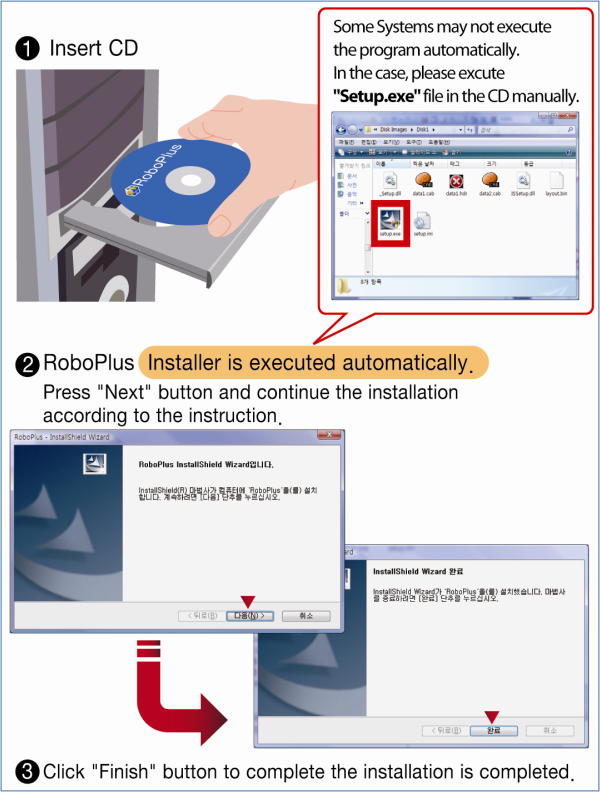
Install
DownloadRoboPlus
RoboPlus is a software to create a customized programme for every ROBOTIS product.
RoboPlus System Requirements
- OS : Windows XP Service Pack 2 or above / Vista/ 7 (32/64bit)/8 (32/64bit)
- 32bit(x86) or 64bit (x64) processor with over 800MHz
- Graphic card with 3D acceleration
- System memory over 512MB
- Hard disk with the extra space of 500MB
NOTE : To execute RoboPlus, .NET FrameWork 3.5 or higher version is required. When installing RoboPlus, if the automatic installation of .NET FrameWork fails, .NET FrameWork must be installed separately.
RoboPlus Install Failure
Most reason for installation failure is caused by .NET Framework install error. Please manually intsall Windows Installer 3.1 and .NET Framework 3.5
Windows installer and .NET Framework can be downloaded from Microsoft Download Center.
Download Windows installer 3.1, .NET Framework 3.5
Getting Started
Connect Controller
- Connect controller to the PC. (Please refer to each controller information for connecting the controller to the PC.)
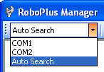
-
Select the communication port to use. Use the “Automatic Search” function to easily select the appropriate port.
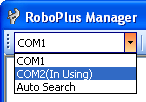
If the chosen communication port is being used by another program, you must first find and stop the program.
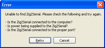
If RoboPlus Manager is unable to find a controller, the following error message will be shown.
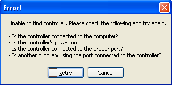
- Check if the controller is connected to the PC. (See controller information for information on how to connect the controller.)
- Check if the controller is turned on.
- Check if the correct communication port was chosen.
- Start management. (Please refer to the managing information of each controller.)
Firmware Management
Firmware Update
Firmware is the program installed in the controller, and is used to execute .tsk programs or to manage the controller.
RoboPlus Manager automatically connects to the internet and searches for firmware updates.
Updating Controller Firmware
-
When the controller is connected, the controller’s firmware version will be retrieved. If a newer firmware is available, it will ask whether to download the latest firmware.
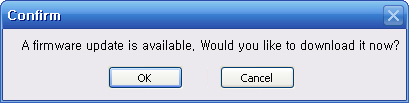
-
When the ‘OK’ button is pressed, it will begin updating the firmware.
-
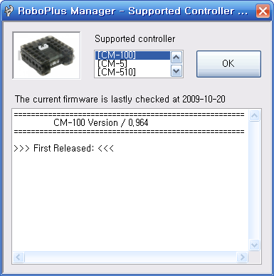
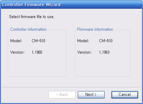
You can check your controller’s model number and firmware version.
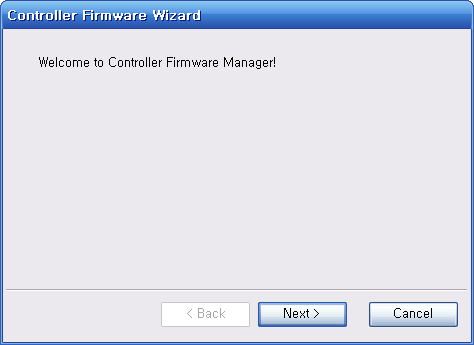
-
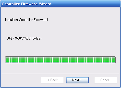
Press the “Next” button to begin updating your firmware. Be careful not to turn the power off or disconnect the cable while the firmware is being updated.
-
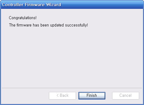
Once the firmware has been updated, Press the “Finish” button to return to the controller maintenance page.
Firmware Recovery
When there is a problem with the controller’s firmware, RoboPlus Manager can be used to recover the firmware.
For CM-150 and CM-200, you will need the latest RoboPlus Manager (ver. 1.0.31.0 or higher) to execute the recovery.
Recover Controller Firmware
-
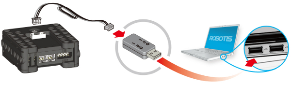
Connect the controller to the PC using LN-101.
-
Run RoboPlus Manager and open the controller firmware management wizard. On the menu bar, click the firmware management button to run the firmware wizard.
(CM-150 and CM-200 require some pre-steps prior to proceeding. Please refer to the message below.)
-
Select the port number for connecting the controller.
Because the firmware is broken, the controller cannot be automatically found. So, you must manually select the port number the controller is connected to.
The controller cannot be found if the port is being used, so please close other programs before proceeding. Select the port number then click search.
-
Turn OFF then turn ON the controller (this process can be skipped for CM-150 and CM-200).
Turn OFF and turn ON the controller to proceed with the recovery -
Check the controller information.
When the controller is found, the information for the firmware to be downloaded will be displayed.
Please check whether the model name is the same as the name of the connected controller (the version on the controller information is the version of the boot loader, not the firmware)
-
Firmware Recovery
-
Check the results of the firmware recovery
Video
How to Use
Controllers
CM-5
When the CM-5 controller is connected to RoboPlus Manager, the following screen is displayed.
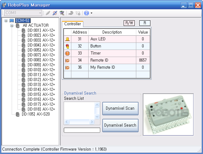
The controller and its peripheral devices are listed in the left window. In the right window is the “controller management” window.
If the controller’s firmware version is older than that of RoboPlus Manager, it can be updated. (Please refer to the Firmware Update section)
General/Detail Search
General Search
- Search for DYNAMIXEL connected at 1Mbps.
- Search speed is fast because it searches for only DYNAMIXEL connected at 1Mbps.
- DYNAMIXEL connected at other speeds are not found.
Detailed Search
- Search for DYNAMIXEL connected at every possible communication speed.
- Search speed is slower because it searches for DYNAMIXEL connected at different communication speeds.
- The DYNAMIXEL that are not connected at 1Mbps are automatically adjusted to 1Mbps.
NOTE : If a DYNAMIXEL is no longer detected after a detailed search, there might be an ID duplication. In this case, connect only the undetected device, and change its ID to an unused one. (Refer to the Change ID of DYNAMIXEL.)
Aux LED
This parameter is used to turn the controller’s Aux LED on or off.
Characteristic
The controller’s Aux LED can be manipulated using the On/Off button.
Corresponding RoboPlus Task Command
- Parameter : Aux LED
- Constants : True/False
Button
This parameter is used to read the controller’s button status (whether it is pressed).
Characteristic
When a button on the controller is pressed, you can see which button has been pressed.
Corresponding RoboPlus Task Command
- Parameter : Button
- Constant: Button
Timer
This parameter is used to set or read the controller’s timer.
Characteristics
- The timer can be set and the actual time can be checked.
- Timer value is between 0 and 255.
- When the timer is set, it will start to count every 0.128 seconds, and you will be able to see how much time is left.
Corresponding RoboPlus Task Command
- Parameter : Timer
- Constants : Timer Values
Remocon ID
The parameter is used to set or read the ID of the ZigBee communication module that communicates with the robot’s Zigbee module.
Characteristics
- This parameter is meaningful only when ZigBee module is connected.
- The ID is a number between 0 and 65535.
- When the opponent’s ID is set to 65535, data is sent to all ZigBee modules, regardless of ID.
- For 1:1 communication, the ID’s of both ZigBee modules must be correct.
Corresponding RoboPlus Task Command
- Parameter : Remocon ID
- Constant : Number
My ID
This parameter is used to read the ID of the ZigBee module installed in my robot.
Characteristics
- If a ZigBee module is not installed, 0 will be returned.
- If a ZigBee module is installed, its ID is read (a number between 0 and 65534).
Corresponding RoboPlus Task Command
- Parameter : My ID
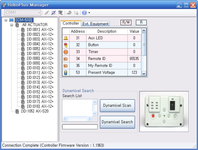
CM-510
When the CM-510 controller is connected to RoboPlus Manager, the following screen is displayed.

The controller and its peripheral devices are listed in the left window. In the right window is the “controller management” window.
If the controller’s firmware version is older than that of RoboPlus Manager, it can be updated. (Please refer to the Firmware Update section)
General/Detail Search
General Search
- Search for DYNAMIXEL connected at 1Mbps.
- Search speed is fast because it searches for only DYNAMIXEL connected at 1Mbps.
- DYNAMIXEL connected at other speeds are not found.
Detailed Search
- Search for DYNAMIXEL connected at every possible communication speed.
- Search speed is slower because it searches for DYNAMIXEL connected at different communication speeds.
- The DYNAMIXEL that are not connected at 1Mbps are automatically adjusted to 1Mbps.
NOTE : If a DYNAMIXEL is no longer detected after a detailed search, there might be an ID duplication. In this case, connect only the undetected device, and change its ID to an unused one. (Refer to the Change ID of DYNAMIXEL.)
Aux LED
This parameter is used to turn the controller’s Aux LED on or off.
Characteristic
The controller’s Aux LED can be manipulated using the On/Off button.
Corresponding RoboPlus Task Command
- Parameter : Aux LED
- Constants : True/False
Button
This parameter is used to read the controller’s button status (whether it is pressed).
Characteristic
When a button on the controller is pressed, you can see which button has been pressed.
Corresponding RoboPlus Task Command
- Parameter : Button
- Constant: Button
Timer
This parameter is used to set or read the controller’s timer.
Characteristics
- The timer can be set and the actual time can be checked.
- Timer value is between 0 and 255.
- When the timer is set, it will start to count every 0.128 seconds, and you will be able to see how much time is left.
Corresponding RoboPlus Task Command
- Parameter : Timer
- Constants : Timer Values
Remocon ID
The parameter is used to set or read the ID of the ZigBee communication module that communicates with the robot’s Zigbee module.
Characteristics
- This parameter is meaningful only when ZigBee module is connected.
- The ID is a number between 0 and 65535.
- When the opponent’s ID is set to 65535, data is sent to all ZigBee modules, regardless of ID.
- For 1:1 communication, the ID’s of both ZigBee modules must be correct.
Corresponding RoboPlus Task Command
- Parameter : Remocon ID
- Constant : Number
My ID
This parameter is used to read the ID of the ZigBee module installed in my robot.
Characteristics
- If a ZigBee module is not installed, 0 will be returned.
- If a ZigBee module is installed, its ID is read (a number between 0 and 65534).
Corresponding RoboPlus Task Command
- Parameter : My ID
Sound Count
Sounds can be detected using the microphone in the controller.
Characteristics
- When a sound louder than a certain threshold, such as a clap, is made near the controller, it will be detected by the controller’s microphone.
- The maximum number of sounds counted is 255.
- When sounds are no longer detected, the number of detected sounds will be input into the “Sound Count” parameter.
- Because “Sound Count” is not initialized automatically, the user must reset it to 0 before use.
Corresponding RoboPlus Task Command
- Parameter : Sound Count
Current Sound Count
It is also possible to know how many sounds have been counted by the controller’s microphone so far.
Characteristics
- The maximum number of sounds counted is 255.
- The parameter value is increased in real-time whenever a sound is detected.
- If a new sound is not detected for a certain period, the value of the “Current Sound Count” parameter is passed to the “Sound Count” parameter, and the “Current Sound Count” parameter is reset to 0.
Corresponding RoboPlus Task Command
- Parameter : Current Sound
Buzzer Index
This parameter is used to set the musical note played by the controller’s buzzer.
Characteristics
- Depending on what the “Buzzer Time” is set to, “Buzzer Index” can be set to play a musical note or a melody. Please refer to the “Buzzer Time” parameter for information on sound modes.
- If the “Buzzer Time” parameter is not set to melody mode, a melody will not be played even if it is selected.
- In musical note mode, the note will be played for the length set as “Buzzer Time.”
- In melody mode, when a melody is set, it is played to the end.
- There are 16 melodies (0-15) and 27 musical notes (0-26).
- If the “Buzzer Time” is 0, the parameter is automatically set to 3 and the note is played.
Corresponding RoboPlus Task Command
- Parameter : Buzzer Type
- Constants : Melody, Scale Values.
Buzzer Time
This parameter is used to set the sound mode and how long the note or melody will be played.
Characteristics
- If the “Buzzer Time” parameter is set to a value between 0 and 50, the sound mode is set to musical note mode. The note will be played for the length set as “Buzzer Time.”
- If the “Buzzer Time” parameter is set to 255, the sound mode is set to melody mode.
- When the note or melody finishes playing, “Buzzer Time” is automatically reset to 0.
Corresponding RoboPlus Task Command
- Parameter : Buzzer Time
- Constant Numbers : Melody, Scale Values
Exterior I/O Devices
The controller supports exterior I/O devices, such as IR sensors, touch sensors, and DMS sensors.
Characteristics
- Most devices support only reads, but a few also allow writes.
- After connecting and setting up an exterior I/O device, you can check its values.
- For user’s devices, you can set which values are returned.
- Exterior I/O devices are not recognized automatically, so the user must manually set the device.
- IR sensors, touch sensors, DMS Sensors, and user’s devices are supported.
- If you read without connecting a device, a random value will be returned. This value is meaningless.
- When the port and device are set, the address will be set automatically. This address can be used during programing.
Corresponding RoboPlus Task Command
- Parameter : User’s Devices
CM-530
When the CM-530 controller is connected to RoboPlus Manager, the following screen is displayed.
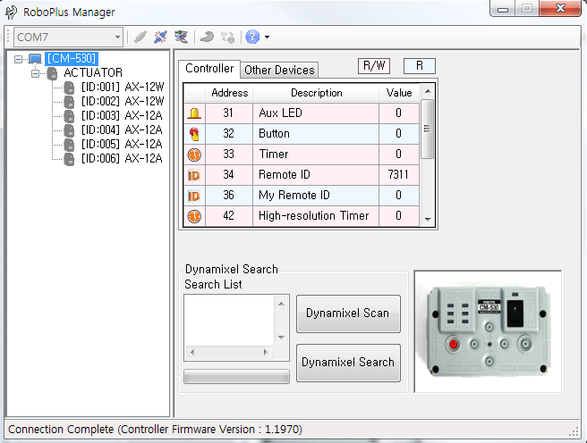
The controller and its peripheral devices are listed in the left window. In the right window is the “controller management” window.
If the controller’s firmware version is older than that of RoboPlus Manager, it can be updated. (Please refer to the Firmware Update section)
General/Detail Search
General Search
- Search for DYNAMIXEL connected at 1Mbps.
- Search speed is fast because it searches for only DYNAMIXEL connected at 1Mbps.
- DYNAMIXEL connected at other speeds are not found.
Detailed Search
- Search for DYNAMIXEL connected at every possible communication speed.
- Search speed is slower because it searches for DYNAMIXEL connected at different communication speeds.
- The DYNAMIXEL that are not connected at 1Mbps are automatically adjusted to 1Mbps.
NOTE : If a DYNAMIXEL is no longer detected after a detailed search, there might be an ID duplication. In this case, connect only the undetected device, and change its ID to an unused one. (Refer to the Change ID of DYNAMIXEL.)
Aux LED
This parameter is used to turn the controller’s Aux LED on or off.
Characteristic
The controller’s Aux LED can be manipulated using the On/Off button.
Corresponding RoboPlus Task Command
- Parameter : Aux LED
- Constants : True/False
Button
This parameter is used to read the controller’s button status (whether it is pressed).
Characteristic
When a button on the controller is pressed, you can see which button has been pressed.
Corresponding RoboPlus Task Command
- Parameter : Button
- Constant: Button
Timer
This parameter is used to set or read the controller’s timer.
Characteristics
- The timer can be set and the actual time can be checked.
- Timer value is between 0 and 255.
- When the timer is set, it will start to count every 0.128 seconds, and you will be able to see how much time is left.
Corresponding RoboPlus Task Command
- Parameter : Timer
- Constants : Timer Values
High Resolution Timer
Internally the controller sets a counter; this is the parameter for the high resolution timer. This timer is set for every 1ms, useful for more accurate timing.
Characteristics
- The timer can be set and the actual time can be checked.
- Timer value is between 0 and 65535. Timers shows 1 unit for every 1ms
- When the timer is set, it will start to count every 0.001 seconds, and you will be able to see how much time is left.
Corresponding RoboPlus Task Command
- Parameter : HR Timer
- Constants : Timer Values
Remocon ID
The parameter is used to set or read the ID of the ZigBee communication module that communicates with the robot’s Zigbee module.
Characteristics
- This parameter is meaningful only when ZigBee module is connected.
- The ID is a number between 0 and 65535.
- When the opponent’s ID is set to 65535, data is sent to all ZigBee modules, regardless of ID.
- For 1:1 communication, the ID’s of both ZigBee modules must be correct.
Corresponding RoboPlus Task Command
- Parameter : Remocon ID
- Constant : Number
My ID
This parameter is used to read the ID of the ZigBee module installed in my robot.
Characteristics
- If a ZigBee module is not installed, 0 will be returned.
- If a ZigBee module is installed, its ID is read (a number between 0 and 65534).
Corresponding RoboPlus Task Command
- Parameter : My ID
Sound Count
Sounds can be detected using the microphone in the controller.
Characteristics
- When a sound louder than a certain threshold, such as a clap, is made near the controller, it will be detected by the controller’s microphone.
- The maximum number of sounds counted is 255.
- When sounds are no longer detected, the number of detected sounds will be input into the “Sound Count” parameter.
- Because “Sound Count” is not initialized automatically, the user must reset it to 0 before use.
Corresponding RoboPlus Task Command
- Parameter : Sound Count
Current Sound Count
It is also possible to know how many sounds have been counted by the controller’s microphone so far.
Characteristics
- The maximum number of sounds counted is 255.
- The parameter value is increased in real-time whenever a sound is detected.
- If a new sound is not detected for a certain period, the value of the “Current Sound Count” parameter is passed to the “Sound Count” parameter, and the “Current Sound Count” parameter is reset to 0.
Corresponding RoboPlus Task Command
- Parameter : Current Sound
Buzzer Index
This parameter is used to set the musical note played by the controller’s buzzer.
Characteristics
- Depending on what the “Buzzer Time” is set to, “Buzzer Index” can be set to play a musical note or a melody. Please refer to the “Buzzer Time” parameter for information on sound modes.
- If the “Buzzer Time” parameter is not set to melody mode, a melody will not be played even if it is selected.
- In musical note mode, the note will be played for the length set as “Buzzer Time.”
- In melody mode, when a melody is set, it is played to the end.
- There are 16 melodies (0-15) and 27 musical notes (0-26).
- If the “Buzzer Time” is 0, the parameter is automatically set to 3 and the note is played.
Corresponding RoboPlus Task Command
- Parameter : Buzzer Type
- Constants : Melody, Scale Values.
Buzzer Time
This parameter is used to set the sound mode and how long the note or melody will be played.
Characteristics
- If the “Buzzer Time” parameter is set to a value between 0 and 50, the sound mode is set to musical note mode. The note will be played for the length set as “Buzzer Time.”
- If the “Buzzer Time” parameter is set to 255, the sound mode is set to melody mode.
- When the note or melody finishes playing, “Buzzer Time” is automatically reset to 0.
Corresponding RoboPlus Task Command
- Parameter : Buzzer Time
- Constant Numbers : Melody, Scale Values
Exterior I/O Devices
The controller supports exterior I/O devices, such as IR sensors, touch sensors, and DMS sensors.
Characteristics
- Most devices support only reads, but a few also allow writes.
- After connecting and setting up an exterior I/O device, you can check its values.
- For user’s devices, you can set which values are returned.
- Exterior I/O devices are not recognized automatically, so the user must manually set the device.
- IR sensors, touch sensors, DMS Sensors, and user’s devices are supported.
- If you read without connecting a device, a random value will be returned. This value is meaningless.
- When the port and device are set, the address will be set automatically. This address can be used during programing.
Corresponding RoboPlus Task Command
- Parameter : User’s Devices
CM-700
When the CM-700 controller is connected to RoboPlus Manager, the following screen is displayed.
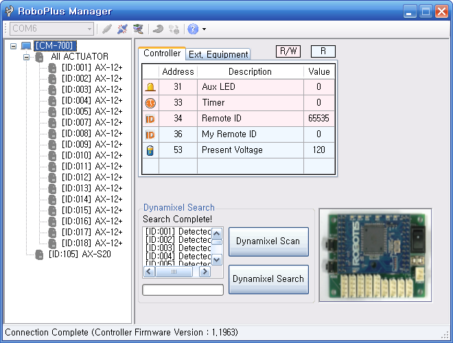
The controller and its peripheral devices are listed in the left window. In the right window is the “controller management” window. (Please refer to the “Test” page).
If the controller’s firmware version is older than that of RoboPlus Manager, it can be updated. (Please refer to the Firmware Update section)
General/Detail Search
General Search
- Search for DYNAMIXEL connected at 1Mbps.
- Search speed is fast because it searches for only DYNAMIXEL connected at 1Mbps.
- DYNAMIXEL connected at other speeds are not found.
Detailed Search
- Search for DYNAMIXEL connected at every possible communication speed.
- Search speed is slower because it searches for DYNAMIXEL connected at different communication speeds.
- The DYNAMIXEL that are not connected at 1Mbps are automatically adjusted to 1Mbps.
NOTE : If a DYNAMIXEL is no longer detected after a detailed search, there might be an ID duplication. In this case, connect only the undetected device, and change its ID to an unused one. (Refer to the Change ID of DYNAMIXEL.)
Aux LED
This parameter is used to turn the controller’s Aux LED on or off.
Characteristic
The controller’s Aux LED can be manipulated using the On/Off button.
Corresponding RoboPlus Task Command
- Parameter : Aux LED
- Constants : True/False
Timer
This parameter is used to set or read the controller’s timer.
Characteristics
- The timer can be set and the actual time can be checked.
- Timer value is between 0 and 255.
- When the timer is set, it will start to count every 0.128 seconds, and you will be able to see how much time is left.
Corresponding RoboPlus Task Command
- Parameter : Timer
- Constants : Timer Values
Remocon ID
The parameter is used to set or read the ID of the ZigBee communication module that communicates with the robot’s Zigbee module.
Characteristics
- This parameter is meaningful only when ZigBee module is connected.
- The ID is a number between 0 and 65535.
- When the opponent’s ID is set to 65535, data is sent to all ZigBee modules, regardless of ID.
- For 1:1 communication, the ID’s of both ZigBee modules must be correct.
Corresponding RoboPlus Task Command
- Parameter : Remocon ID
- Constant : Number
My ID
This parameter is used to read the ID of the ZigBee module installed in my robot.
Characteristics
- If a ZigBee module is not installed, 0 will be returned.
- If a ZigBee module is installed, its ID is read (a number between 0 and 65534).
Corresponding RoboPlus Task Command
- Parameter : My ID
Exterior I/O Devices
The controller supports exterior I/O devices, such as IR sensors, touch sensors, and DMS sensors.
Characteristics
- Most devices support only reads, but a few also allow writes.
- After connecting and setting up an exterior I/O device, you can check its values.
- For user’s devices, you can set which values are returned.
- Exterior I/O devices are not recognized automatically, so the user must manually set the device.
- IR sensors, touch sensors, DMS Sensors, and user’s devices are supported.
- If you read without connecting a device, a random value will be returned. This value is meaningless.
- When the port and device are set, the address will be set automatically. This address can be used during programing.
Corresponding RoboPlus Task Command
- Parameter : User’s Devices
DYNAMIXEL
In the program as shown below, users can set up and test DYNAMIXEL.
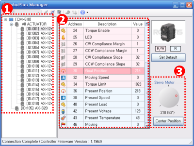
- DYNAMIXEL found using the “Scan” or “Search” function are listed. All devices connected to the controller, including sensors such as AX-S1, are detected. .
- Choose an actuator to manage from the list on the left.
- Parameters that can be set and tested for each device are shown in the table. Clicking on DYNAMIXEL Name/ID will call a subwindow to set or test the parameter. The subwindow simplifies the process of setting the parameter for the user.
- The image above is a screen shot of RoboPlus manager when the “Goal Position” parameter is clicked. A subwindow is shown on the lower right hand corner when any row is clicked. However, no subwindow will be displayed if only values need to be shown.
NOTE : When an actuator with an ID in ① is double clicked, the actuator is selected and its LED will blink for a moment. This is used to check where the actuator is located.
NOTE : Actuators can be managed in a group.
ID Setup
Each DYNAMIXEL has its own ID, and the controller manages each DYNAMIXEL using its ID. This parameter is used to manage DYNAMIXEL ID.
(Please refer to DYNAMIXEL Management for more information about changing ID)
Characteristics
- Once this value is set, it will be saved, even when the power is turned off.
- Click on the ID list to see a list of ID’s that can be changed.
- Values not shown in the ID list are being used by other DYNAMIXEL.
- An ID may be any number between 0 and 253, except 200, which is reserved for the controller.
Position Limit and Mode
This parameter is used to limit the position of the actuator or to set the movement mode.
(Please refer to Changing the Movement Mode for more information about changing Movement Mode)
Characteristics
- Once this value is set, it will be saved even when the power is turned off.
- The position limitation value for both clockwise and counterclockwise rotation can be set, and its value affects the value of the “Goal Position” parameter.
- The actual angle for the set value is displayed.
Movement Mode
- Wheel Mode
- When both the CW Postition Limitation Value and CCW Position Limitation Value are set to 0, the movement mode is set to Wheel Mode (Endless Rotation Mode).
- When the “Wheel Mode” button is pressed, the position limitation values are automatically set to 0.
- Joint Mode
- The actuator will operate in Joint Mode in all other cases.
Drive Mode
Tis parameter is used to set the drive mode of EX actuators. Depending on the drive mode, the Ex actuator’s special modes, such as dual mode and reverse mode can be used. Please refer to EX-series Dual Mode Setting for detailed information about drive mode.
Characteristics
- Master/Slave and Normal/Reverse modes can be set.
- The setting values of an actuator in slave mode will be synchronized with the setting values of the master actuator.
- When the Master/Slave mode is set, the control table will be updated to reflect the mode.
(For example, in slave mode, the position value cannot be set. Therefore, RoboPlus Manager does not display tables for unnecessary values. ) - In reverse mode, the position values are reversed.
(Position values 0 and 4,095 have opposite meanings as goal position values.)
Temperature Setting
This parameter is used to set the temperature limit for DYNAMIXEL movement.
Characteristics
- Once this value is set, it will be saved even when the power is turned off.
- The actual temperature for the set value is displayed.
- If the actuator’s temperature goes over the limit, the LED will blink or the actuator will stop moving depending on the setting.
- Unless otherwise specified, it is recommended to use the default value.
Temperature
This parameter is used to read DYNAMIXEL current temperature.
Characteristic
- The DYNAMIXEL temperature is returned in real-time.
Corresponding RoboPlus Task Command
- Parameter : Temperature
Voltage Setting
This parameter is used to set the voltage limit for DYNAMIXEL movement.
Characteristics
- Once this value is set, it will be saved even when the power is turned off.
- The actual voltage for the set value is displayed.
- The maximum voltage value and minimum voltage value can be set.
- If the actuator’s voltage exceeds the limit, the LED will blink or the actuator will stop moving depending on the setting.
- Unless otherwise specified, it is recommended to use the default value.
Voltage
This parameter is used to read DYNAMIXEL current voltage.
Characteristic
- The DYNAMIXEL voltage is returned in real-time.
Corresponding RoboPlus Task Command
- Parameter : Voltage
Alarm & Shutdown
The LED alarm or shutdown operation can be set for specific cases.
Parameter Characteristics
- Once this value is set, it will be saved even when the power is turned off.
- The actuator can be set to automatically stop its movements using the shutdown operation.
- By using the shutdown operation, DYNAMIXEL can be protected from problematic situations, such as current overloads, overheating, and abnormal movements.
- The LED alarm or shutdown operation can be triggered by the following errors.
- Instruction Error : A wrong command is received.
- Overload Error : The current load is larger than the limit.
- Checksum Error : The checksum of the received command is incorrect.
- Range Error : The received command requires movements that are outside the actuator’s boundaries.
- Overheating Error : The actuator’s current temperature is higher than the maximum operating temperature
- Angle Limit Error : The actuator has moved farther than its limit.
- Input Voltage Error : The input voltage is lower than the minimum possible voltage or has exceeded the maximum possible voltage
Torque Enable
This parameter is used to turn the actuator on or off.
Characteristics
- If the value is 0, the actuator’s torque is turned off. i.e. the horn is free to rotate. If the value is 1, the actuator’s torque is turned on.
- The torque can easily be turned on or off using the On/Off command.
- If the goal position is set when the actuator is turned off, the actuator will automatically turn on and this parameter will be set to 1.
Corresponding RoboPlus Task Command
- Parameter : Torque Enable
- Constants : True /False
LED
This parameter is used to turn DYNAMIXEL LED on or off.
Characteristics
- If the value is 0, the LED is turned off. If the value is 1, it is turned on.
- The LED can easily be turned on or off using the On/Off command.
- The LED cannot be manipulated when the LED alarm is triggered.
Corresponding RoboPlus Task Command
- Parameter : LED
- Constants : True/False
CW/CCW Margin
This parameter is used to set the actuator’s compliance margin.
Parameter Characteristics
- The margin designates the area around the goal position that receives no torque.
- Set appropriate values for CW/CCW slope, “torque limit, “ and “CW/CCW margin,” for smoother movements.
Corresponding RoboPlus Task Command
- Parameter : CW/CCW Margin
CW/CCW Slope
This parameter is used to set the actuator’s compliance slope.
Parameter Characteristics
- The slope value will be created at both CW/CCW directions, and the output level will be set near the target position.
- If you set the lower slope value, it will reach to the target position by reducing the initial power NOT that much. On the contrary, if you set the higher value, it will reach the target position by reducing considerable powers as it reaches to the goal.
- If you set the lower slope value, it will resist with maximum power not to stray from target position.
- Even if you set the higher value, it will resist with more and more power if it is strayed too much from target position.
- Compliance Slope will be changed into 7 Data representative values according to the input Data. In other words, if you input 25, in real operation, 16 -the representative value of 25-, will be used.
| Level | Real Data Value | Representative Data Value |
|---|---|---|
| 1 | 0 (0x00) ~ 3(0x03) | 2 (0x02) |
| 2 | 4(0x04) ~ 7(0x07) | 4 (0x04) |
| 3 | 8(0x08)~15(0x0F) | 8 (0x08) |
| 4 | 16(0x10)~31(0x1F) | 16 (0x10) |
| 5 | 32(0x20)~63(0x3F) | 32 (0x20) |
| 6 | 64(0x40)~127(0x7F) | 64 (0x40) |
| 7 | 128(0x80)~254(0xFE) | 128 (0x80) |
- Appropriate Compliance Slope, Power control, and the Compliance Margin values will make it possible to create smoother movement.
Corresponding RoboPlus Task Command
Parameter : CW/CCW Slope
Goal Position
This parameter is used to set the actuator’s goal position.
Characteristics
- The value can be set using a jog dial.
- When this value is set, the actuator will immediately move to the goal position.
- The value is affected by “moving speed,”position limitation,” “CW/CCW slope,” and “CW/CCW margin” parameters.
- Even when the torque is turned off, as soon as the value is set, it will be turned on.
- When the “center position” button is pressed, the value is set to the center position.
Corresponding RoboPlus Task Command
- Parameter : Goal Position
- Constants : Position Values
Moving Speed
This parameter is used to set the speed of the actuator.
Characteristics
- In joint mode, the speed is affected by “compliance slope” and “compliance margin” values.
- In joint mode, set the value as 0 to output at maximum power.
- In wheel mode (endless rotation mode), the speed and rotating direction depend on the “moving speed” value.
- The movement mode can be set using the “position limitation” parameter.
- The control used to set the speed is different for each mode.
Corresponding RoboPlus Task Command
- Parameter :Moving Speed
- Constants : Motor Control Values
Torque Limit
This parameter is used to set the maximum load on the actuator.
Characteristic
- The LED alarm may be triggered or the movement may be stopped depending on the torque limit, LED alarm, and shutdown settings.
Corresponding RoboPlus Task Command
- Parameter : Torque Limit
Present Position
This parameter is used to read the actuator’s current position.
Characteristic
- The value changes in real-time to reflect the actuator’s movement.
Corresponding RoboPlus Task Command
- Parameter : Present Position
Present Speed
This parameter is used to read the actuator’s current speed.
Characteristic
- The value changes in real-time to reflect the actuator’s movement.
Corresponding RoboPlus Task Command
- Parameter : Present Speed
Present Load
This parameter is used to read the actuator’s current load.
Characteristics
- The value changes in real-time to reflect the actuator’s movement.
- When the motor is turned off, this value is meaningless.
RoboPlus Task Referring Command
- Parameter : [Present Load]
Moving
This parameter is used to determine whether the actuator is currently moving or not.
Characteristic
- If the value is 0, it is not moving. If the value is 1, it is moving.
Corresponding RoboPlus Task Command
- Parameter: Moving
Sensed Current
This parameter is used to check the current being consumed.
Characteristics
EX-Series
- If the value is 512, the current is 0 ampere. That is, there is no current flowing.
- If the value is larger than 512, the current is rotating the motor clockwise, and the size of the current is proportional to the size of the data. (1 = aprroximately 10 mA)
- For example, if the data is 612, 1A (612-512=100 => 100x10mA = 1,000mA) is being used to rotate the motor in the clockwise direction.
- If the value is smaller than 512, the current is rotating the counterclockwise, and the size of the current is proportional to the size of the data. (1 = aprroximately 10 mA)
- For example, if the data is 312, 2A (512-312= -200 => 200x10mA = 2,000mA) is being used to rotate the motor in the counterclockwise direction.
MX-Series
- If the value is 2,048, the currnet is 0 ampere. That is, there is no current flowing.
- If current flows in normal direction then output values are larger than 2,048.
- If current flows in the opposite direction then output values are smaller than 2,048
- Current flow values are proportional to data values (value unit of 1 = 4.5mA units)
- For example if data reads 2,148 then 2,148 - 2,048 = 100 -> 100 x 4.5mA = 450mA. The output current is 450mA in the normal direction.
Corresponding RoboPlus Task Command
- Parameter : Sensed Current
PID Gain
For MX-Series actuator PID values read/write availability
Characteristics
- P gain refers to the value of proportional band.
- I gain refers to the value of integral action.
- D Gain refers to the value of derivative action.
- Gains values are in between 0~254.
Corresponding RoboPlus Task Command
- Parameter : PID Gain
IR Left/Center/Right
For AX-S1 these parameters are used to read the DMS sensor value.
Characteristics
- The current DMS sensor value of AX-S1 can be read.
- The reflection angle of IR rays are measured, so objects the same distance away may return different values due to their color or surrounding light.
- The sensor value is between 0 and 255.
Corresponding RoboPlus Task Command
- Parameter : IR Left/Center/Right
Light Left/Center/Right
For AX-S1 this parameter is used to read the light brightness.
Characteristics
- The current light brightness value of AX-S1 can be read.
- The infrared rays emitted by nearby light sources such as candles and light bulbs can be measured.
- The sensor value is between 0 and 255.
Corresponding RoboPlus Task Command
- Parameter : Light Left/Center/Right
Object Detected
For AX-S1 this parameter is used to determine whether an object is detected.
Characteristics
- If an object is detected within a certain distance, specific bits are set as 1.
- From the left, the first bit represents the left sensor, the second bit represents the center sensor, and the third bit represents the right sensor.
- Values are returned as a combination of the bits.
RoboPlus Task Referring Command
- Parameter : Object Detected
- Constants : Binary numbers
Object Detection Threshold
For AX-S1 this parameter is used to set the object detection threshold.
Characteristics
- Set the object detection threshold to be used when determining whether an object is detected or not.
- The value is between 0 and 255.
- There is a short-range detection mode and a long-distance detection mode.
- The short-range detection mode is activated when the threshold value is set as.
Corresponding RoboPlus Task Command
- Parameter : Object Detection Threshold
Light Detected
For AX-S1 this parameter is used to determine whether a light is detected.
Characteristics
- If the AX-S1’s IR sensor value is greater than the light detection threshold value, set the bits as 1.
- From the left, the first bit represents the left sensor, the second bit represents the center sensor, and the third bit represents the right sensor.
- Values are returned as a combination of the bits.
Corresponding RoboPlus Task Command
- Parameter : Light Detected
- Constants : Binary numbers
Light Detection Threshold
For AX-S1 this parameter is used to set the light detection threshold.
Characteristics
- Set the threshold to be used when determining whether a light is detected or not.
- The value is between 0 and 255.
Corresponding RoboPlus Task Command
- Parameter : Light Detection Threshold
Sound Data
For AX-S1 this parameter is used to read the volume of the sound detected.
Characteristics
- Reads the volume of the sound being detected by AX-S1.
- If no sounds are detected, the returned value will be near 127. When sounds are detected, the value will change according to the volume. (The louder the sound, the more the value will fluctuate from 127 to 0 and 255 is not clear. Whether the value will go up or down to sound value.)
- The value is between 0 and 255.
Corresponding RoboPlus Task Command
- Parameter : Sound Data
Sound Max Data
For AX-S1 this parameter is used to read the volume of the loudest sound detected.
Characteristics
- Reads the maximum sound data detected by AX-S1.
- If the detected volume is louder than the volume of the loudest sound up to that point, the max sound data is replaced with the detected value.
- The value is between 0 and 255.
- Because “Sound Max Data” is not initialized automatically, the user must reset it to 0 before use.
Corresponding RoboPlus Task Command
- Parameter : Sound Max Data
Sound Count
TheAX-S1 is equipped with a function to count sounds louder than a certain threshold. For example, it is possible to count claps. This parameter is used to read or initialize the number of detected sounds.
Characteristics
- “Sound Count” uses numbers between 0 and 255.
- When sounds are no longer detected, the number of detected sounds will be input into the “Sound Count” parameter.
- Because “Sound Count” is not initialized automatically, the user must reset it to 0 before use.
Corresponding RoboPlus Task Command
- Parameter : Sound Count
Buzzer Index
AX-S1 is equipped with a buzzer. This parameter is used to set the musical note played by the buzzer.
Characteristics
- After setting “Buzzer Time,” set “Buzzer Index” to play a sound using the buzzer.
- There are 52 musical notes that can be played (0-51).
- There are 27 melodies that can be played (0-26).
- Depending on what the “Buzzer Time” is set to, “Buzzer Index” can be set to play a musical note or a melody.
Corresponding RoboPlus Task Command
- Parameter : Buzzer Index
Buzzer Time
AX-S1 is equipped with a buzzer. This parameter is used to set how long the sound is played by the buzzer.
Characteristics
- After setting “Buzzer Time,” set “Buzzer Index” to play a sound using the buzzer.
- “Buzzer Time” can be set to a value between 0 and 50. Each value represents 0.1 second.
- When it is set to 254, the sound will play without end.
- When it is set to 255, melodies will be played.
- When the melody finishes playing, “Buzzer Time” is reset to 0.
Corresponding RoboPlus Task Command
- Parameter : Buzzer Time
IR Sensor Value
For IR Sensor Array these parameters are used to read the current IR sensor value.
Characteristics
- Can read IR array’s current sensor values.
- The IR array’s receivers can detect walls and obstacles by measuring the amount of infrared reflection bouncing back. The closer the object the higher the value.
- The sensor value is between 0 and 1023.
Corresponding RoboPlus Task Command
- Parameter : IR Sensor Value
Auto Threshold Mode
For IR Sensor Array Setting for start/set for automatic detection for set black.
Characteristics
- Once LED’s blink when turned on and set values are on.
- When crossing between white and black the IR sensors automatically set values.
- Powers off when turned off.
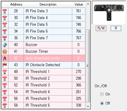
Corresponding RoboPlus Task Command
- Parameter : Auto Threshold Mode
IR Obstacle Detected
For IR Sensor Array Paramenters to determine IR array obstacle values
Characteristics
- In the IR array if each IR sensor detected black value is lower than the set black valuethe values will be assigned as shown below; the LED turns on.
- Output values are in decimal number.
| Binary value | Decimal value | Black detection |
|---|---|---|
| 0000001 | 1 | Black detection for IR sensor #1 |
| 0000010 | 2 | Black detection for IR sensor #2 |
| 0000100 | 4 | Black detection for IR sensor #3 |
| 0001000 | 8 | Black detection for IR sensor #4 |
| 0010000 | 16 | Black detection for IR sensor #5 |
| 0100000 | 32 | Black detection for IR sensor #6 |
| 1000000 | 64 | Black detection for IR sensor #7 |
Corresponding RoboPlus Task Command
- Parameter : IR Obstacle Detected
Set IR Threshold
For IR Sensor Array Determine set values for black and white for the IR array.
Characteristics
- Setting infrared values for presence of obstacles.
- Overall set values can be set by automatic parameter setting.
- Values range from 0 to 1,023.
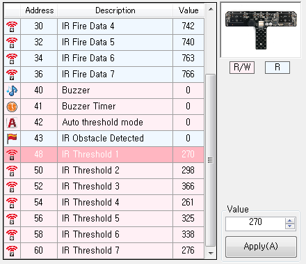
Corresponding RoboPlus Task Command
- Parameter : Set IR Threshold
ZIG2Serial
Follow these steps to manage the Zig-100 module through RoboPlus Manager using Zig2Serial.
-
Attach Zig-100 to Zig2Serial and connect Zig2Serial to the PC’s serial port.(Please refer to ZIG2Serial for connection)
If your PC does not have a serial port, you may use USB2DYNAMIXEL, as in the picture below.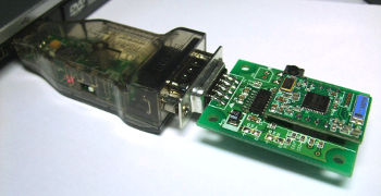
-
Select the port to which Zig2Serial is connected and click the “Zig2Serial Management” icon.
(Unlike with a controller, this port cannot be detected automatically.)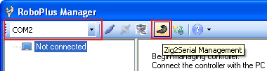
-
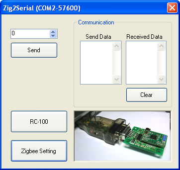
The following screen is displayed when the “Zig2Serial Management” icon is pressed. Click the “Zigbee Setting” button.
-
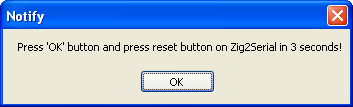
Press the reset button within 3 seconds of clicking “OK”.
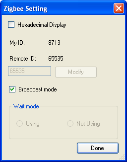
- When the Zigbee module is connected, a window to set functions is displayed.
- Can check my ID and remote ID.
- Can change the remote ID.
- Can set to “Broadcast” mode.
- Can set to “Wait” mode.
-
If no ZIg100 module is detected, check whether the module has been connected properly.
- You can send/receive data to/from other wireless communication modules or create and send RC-100 remote control signals.