
Introduction
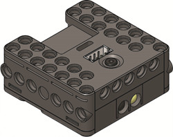
CM-151
- Used with DREAM robots and supports various components used (reduction motors, servo motors, LED modules, IR sensor, etc).
- BLE (Bluethooth Low Energy) function is included.
- Firmware Recovery to CM-151 can be performed using R+ Manager 2.0.
- Control connected components using Task programming such as R+ Task 3.0.
NOTE: R+ Motion does NOT support the CM-151. See Controller Compatibility for more details.
Specifications
| Item | Description |
|---|---|
| Weight | 19.5g |
| Size | 42mm x 42mm x 18mm |
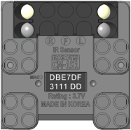
| Voltage Supply | Range : 3.2V ~ 4.2V Recommended : 3.7V (Li-ion Battery x1) |
| Current Consumption | Standby(45mA) Max(140mA) |
| Operation Temperature | -5°C ~ 70°C |
| Wireless Communication | Bluetooth®5 1Mbps Bluetooth® low energy mode Peripheral role (No BR/EDR) |
| Internal I/O components | IR sensor(measure distance) x 3 Mic(Sound sensor) x 1 Buzzer x 1 AUX LED x 1 (GREEN) |
| External I/O components | 4-pin UART communication x 1 Micro USB port (connect to PC) x 1 Motor potrs (for reduction motor) x 2 Multi-usage port(sensor and outputs) x 2 |
![]()
DANGER
(Ignoring these warnings may cause serious injury or death)
- Never place items containing water, flammables/open flames, or solvents near the product.
- Never place fingers, arms, toes, and other body parts near product during operation.
- Cease operation and remove power from the product if the product begins to emit strange odors, noises, or smoke.
- Keep product out of reach of children.
- Check input polarity before installing or energizing wiring or cables.
![]()
CAUTION
(Ignoring these warnings may cause mild injury or damage to the product)
- Always comply with the product’s offical operating environment specifications including input voltage, current, and operating temperature.
- Do not insert blades or other sharp objects during product operation.
![]()
ATTENTION
(Ignoring these warnings may cause minor injury or damage to the product)
- Do not disassemble or modify the product.
- Do not drop the product or apply strong impacts.
- Do not connect or disconnect DYNAMIXEL cables while power is being supplied.
Control Table
Control Table consists of data regarding the current status and operation of controller. The user can control controller by changing data of Control Table via Instruction packet.
-
EEPROM and RAM
Data in RAM area is reset to initial values whenever the power is turned on while data in EEPROM area is kept once values are set even if the power is turned off. -
Address
Represents the location of data. To read from or write data to the control table the user should assign the correct address in the Instruction packet. -
Access
Controller has two kinds of data: Read-only data, used mainly for sensing, and read-and-write data used for driving. -
Initial Value
In case of data in the EEPROM Area, the initial values on the right side of the below Control Table are the factory default settings.
In case of data in the RAM Area, the initial values on the right side of the following control table are the ones when the power is turned on. -
Size
The Size of data varies from 1 ~ 4 bytes depend on their usage. Please check the size of data when updating the data with an Instruction Packet.
EEPROM Area
| Address | Size | Name | Description | Access | Init Value |
|---|---|---|---|---|---|
| 0 | 2 | Model Number | Model Number | R | 460 |
| 6 | 1 | Firmware Version | Firmware Version | R | - |
| 7 | 1 | ID | Controller ID | RW | 200 |
| 8 | 1 | Baud Rate | Communication Baud Rate | R | 1 |
| 11 | 1 | Bootloader Version | Bootloader Version | R | 0 |
RAM Area
| Address | Size | Name | Description | Access | Init Value |
|---|---|---|---|---|---|
| 21 | 1 | Mode Number | Operation Mode | RW | - |
| 25 | 1 | Press Counter | Counts Start Button Press | R | - |
| 36 | 1 | IR Communication Channel | IR Receiver Channel Number | RW | 1 |
| 71 | 2 | Millisecond Delay | 1ms unit Delay | RW | 0 |
| 73 | 1 | 128ms Timer Value | 128ms Timer Counter | RW | 0 |
| 74 | 2 | 1ms Timer Value | 1ms Timer Counter | RW | 0 |
| 76 | 1 | Power Save Timer Value | Power Save Timer Counter | RW | 0 |
| 77 | 1 | Random Number | Creating Random Number | RW | - |
| 79 | 1 | Aux LED (Green) | Green LED Status | RW | 0 |
| 82 | 1 | Motion LED | Motion LED Status | RW | 0 |
| 84 | 1 | Buzzer Index | Buzzer Melody Frequency | RW | 0 |
| 85 | 1 | Buzzer Time | Buzzer Play Time | RW | 0 |
| 86 | 1 | Sound Detected Count | Final Count for Detected Sound | R | 0 |
| 87 | 1 | Sound Detecting Count | Current Count for Detected Sound | R | 0 |
| 91 | 2 | Internal Right IR Sensor Value | Sensor Value of Right IR | R | - |
| 93 | 2 | Internal Left IR Sensor Value | Sensor Value of Left IR | R | - |
| 95 | 2 | Internal Center IR Sensor Value | Sensor Value of Center IR | R | - |
| 128 | 1 | Port 3 Servo Mode | Servo Motor on Port 3 | RW | - |
| 129 | 1 | Port 4 Servo Mode | Servo Motor on Port 4 | RW | - |
| 136 | 2 | Port 3 Motor Speed | Speed of the Motor on Port 3 | RW | - |
| 138 | 2 | Port 4 Motor Speed | Speed of the Motor on Port 4 | RW | - |
| 152 | 2 | Port 1 Motor Speed | Speed of the Motor on Port 1 | RW | - |
| 154 | 2 | Port 2 Motor Speed | Speed of the Motor on Port 2 | RW | - |
| 156 | 2 | Port 3 Servo Position | Position of the Motor on Port 3 | RW | - |
| 158 | 2 | Port 4 Servo Position | Position of the Motor on Port 4 | RW | - |
| 172 | 2 | Port 3 IR Sensor Value | IR Sensor Value on Port 3 | R | - |
| 174 | 2 | Port 4 IR Sensor Value | IR Sensor Value on Port 4 | R | - |
| 204 | 1 | Port 3 Touch Sensor Value | Touch Sensor Value on Port 3 | R | - |
| 205 | 1 | Port 4 Touch Sensor Value | Touch Sensor Value on Port 4 | R | - |
| 212 | 1 | Port 3 LED Module Value | Port 3 LED Module Control Value | RW | 0 |
| 213 | 1 | Port 4 LED Module Value | Port 4 LED Module Control Value | RW | 0 |
| 220 | 2 | Port 3 User Device Value | User Device Value on Port 3 | RW | 0 |
| 222 | 2 | Port 4 User Device Value | User Device Value on Port 4 | RW | 0 |
| 236 | 1 | Port 3 Temperature Sensor Value | Temperature Sensor Value on Port 3 | R | - |
| 237 | 1 | Port 4 Temperature Sensor Value | Temperature Sensor Value on Port 4 | R | - |
| 244 | 1 | Port 3 Ultrasonic Sensor Value | Ultrasonic Sensor Value on Port 3 | R | - |
| 245 | 1 | Port 4 Ultrasonic Sensor Value | Ultrasonic Sensor Value on Port 4 | R | - |
| 252 | 1 | Port 3 Magnetic Sensor Value | Magnetic Sensor Value on Port 3 | R | - |
| 253 | 1 | Port 4 Magnetic Sensor Value | Magnetic Sensor Value on Port 4 | R | - |
| 260 | 1 | Port 3 Motion Sensor Value | Motion Sensor Value on Port 3 | R | - |
| 261 | 1 | Port 4 Motion Sensor Value | Motion Sensor Value on Port 4 | R | - |
| 268 | 1 | Port 3 Color Sensor Value | Color Sensor Value on Port 3 | R | - |
| 269 | 1 | Port 4 Color Sensor Value | Color Sensor Value on Port 4 | R | - |
| 276 | 1 | Port 3 Hydro-Thermo Sensor Humidity Value | Humidity Value on Port 3 | R | - |
| 277 | 1 | Port 4 Hydro-Thermo Sensor Humidity Value | Humidity Value on Port 4 | R | - |
| 284 | 1 | Port 3 Hydro-Thermo Sensor Temperature Value | Temperature Value on Port 3 | R | - |
| 285 | 1 | Port 4 Hydro-Thermo Sensor Temperature Value | Temperature Value on Port 4 | R | - |
| 292 | 2 | Port 3 Brightness Sensor Value | Brightness Sensor Value on Port 3 | R | - |
| 294 | 2 | Port 4 Brightness Sensor Value | Brightness Sensor Value on Port 4 | R | - |
NOTE : Some Addresses of the Control Table can be tested with R+ Manager 2.0.
Layout
- BLE MAC Address: Unique BLE MAC address of CM-151.
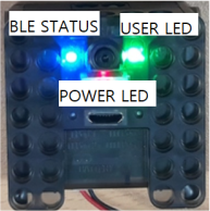
- POWER LED: RED LED indicates if powered on.
- BLE STATUS LED: BLUE LED indicates if paired with BLE Central Device.
- USER LED: GREEN LED can be controlled by user’s program.
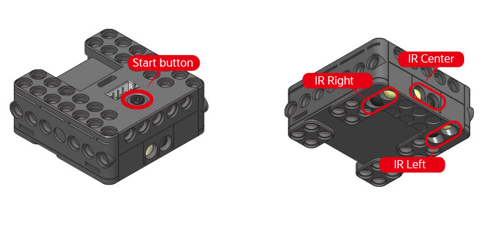
- Start button: After a short press the POWER LED(RED) will turn on and the loaded program runs
- IR sensors : measure each of the integrated 3 IR sensors
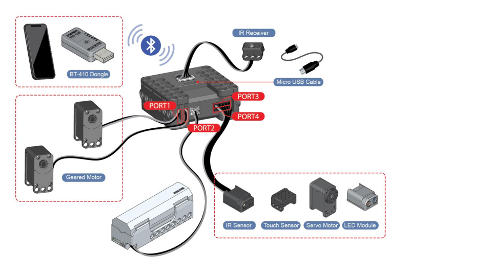
- Bluetooth LE : built-in BLE, possible to connect to BT-410 dongle or Smart Devices.
- Top 4-pin port : located next to the “Start button” connect an IR receiver or BT-210 / BT-110 / ZIG-110 / BT-410 wireless communication modules.
- Micro USB port: located next to the 4-pin port connect a micro USB cable to the PC.
- Port 1 ~ 2 : shown as “I” and “II” connect reduction motors
- Port 3 ~ 4 : shown as “III” and “IIII” connect IR sensors, touch sensors, servo motors and LED modules.
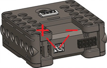
Connecting Power
- Power for the CM-151 is supplied by a single LBS-041 (040) Li-ion battery
- Operating voltage range: 3.0-4.2V (3.7V recommended)
- Power polarity pins are shown in the diagram below
How to Operate
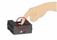
- Press the ”Start button” once shortly. The POWER LED turns on, and the controller runs one downloaded program
- Press the ”Start button” to turn on then press the Start N times. The controller is can run a specific part of a program given said N number of presses.
- Hold the ”Start button” for more than 1 second and it will emit 2 beep sounds, LED turns on, and the controller is under management mode (Downloaded task will not run under this mode).
- To turn off the controller press the ”Start button”
- The controller automatic turn-off time is 5 seconds by default. See Automatic Turn-off for more details.
- Hold the ”Start button” for more than 5 seconds and it will emit 3 beep sounds. The controller is in USB firmware update mode. User can update firmware with R+ Manager 2.0.
- In USB firmware update mode, press “Start button” for 3 times, then the controller will be recovered to last updated firmware after a short “bi-li-li-li-li” melody. The controller will be turned off after firmware recovery.
- In USB firmware update mode, press “Start button” for 1 time, then the controller will be turned off.
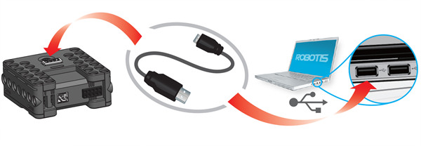
Connect to PC (Micro USB)
- To connect the CM-151 to the PC a micro USB cable is required.
- For more information for PC connection check USB driver installation page.
Wireless Communication
- CM-151 is capable of BLE communication, therefore is compatible with BT-410 Dongle or smart device.
- Connect CM-151 to BT-410 Dongle by placing them within 5cm if the first paring is attempted.
-
Connect Smart Devices to specific CM-151 with unique MAC address of each CM-151.
Mac address of CM-151
- When CM-151 is NOT paired with a BLE Central Device (Smart Phone or BT-410 Dongle, etc.), the BLUE LED of CM-151 will blink.
-
Once CM-151 is paired with a BLE Central Device, the BLUE LED of CM-151 will be turned on without blinking.
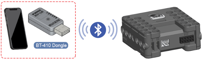
Wireless connection using Smart Device and BT-410 Dongle with CM-151
- Besides, BT-210 / BT-110 / ZIG-110 / BT-410 wireless communication modules can be connected to top 4-pin port.
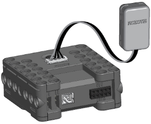
Top 4-pin port
References
Certifications
Please inquire us for information regarding unlisted certifications.
FCC
Note: This equipment has been tested and found to comply with the limits for a Class A digital device, pursuant to part 15 of the FCC Rules. These limits are designed to provide reasonable protection against harmful interference when the equipment is operated in a commercial environment. This equipment generates, uses, and can radiate radio frequency energy and, if not installed and used in accordance with the instruction manual, may cause harmful interference to radio communications. Operation of this equipment in a residential area is likely to cause harmful interference in which case the user will be required to correct the interference at his own expense.
WARNING
Any changes or modifications not expressly approved by the manufacturer could void the user’s authority to operate
the equipment.