Introduction
-
Editing Tab for Each Stage
The editing process of designing is divided into five stages as below, which are proceeded in order. Each tab menu can be accessed using a shortcut by pressing F1~F5 on your keyboard. -
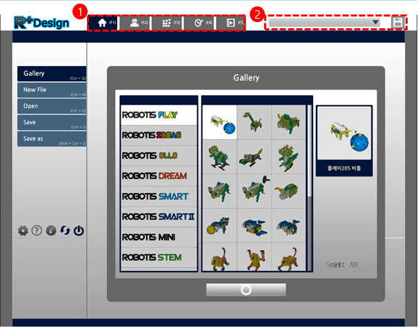
Quick Launch menu
Without moving to the Home tab, a user can open a different design file or save the design file currently being edited.
Home Tab
The Home tab provides the menu for previously created samples and files, and also provides functions of settings and program information.
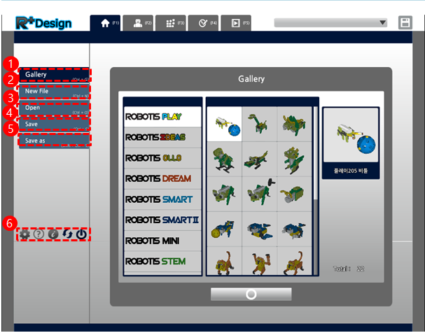
- Gallery : Tab where you can select a sample
- Create New : Create a new design file to assemble a robot
- Open : Open an existing design file
- Save : Save the assembled robot as the design file
- Save As
- Settings, Help, Program Info, Check for Updates, Close
My Robot Tab
My Robot Tab is used to view or modify the information of my robot. Users can edit the name, author, and description of the robot, or view information on the parts used in creating the robot:
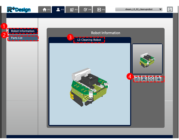
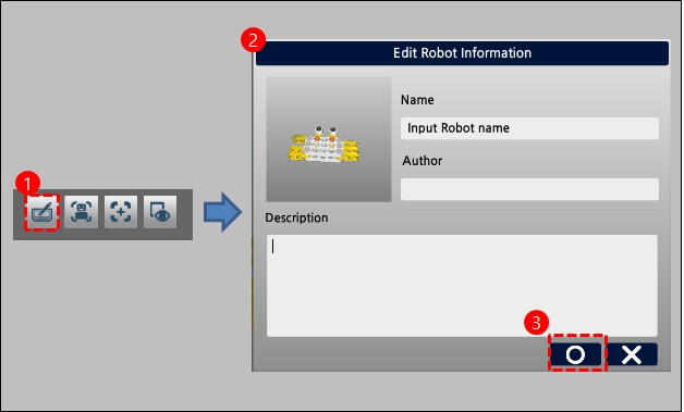
- My Robot Information : Enter and edit information about the robot
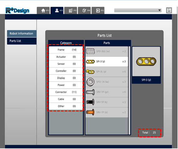
- Parts List : The type and quantity of parts used in assembly
- Robot Name
- Edit Information : The button that opens a window for editing the robot information
- Move center of robot to origin point : Moves the assembled robot to the center of the screen
- Move viewpoint to origin point : Moves the current viewpoint to the center of the screen
- Capture : Save the current image of the robot as the preview image(Capture also sets the default viewpoint of the robot)
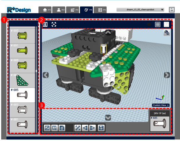
Assembly Tab
The Assembly tab is where the user assemble the robot in a virtual space
- List : A list of the used parts
- Top bar : Add part, Undo, Redo, Move robot to origin, Move viewpoint to origin, Snap On/Off, grid On/Off, Help
- Bottom UI : Rotation UI, Hole-Based Move UI, Move, rotate UI, Select menu, Information on selected part
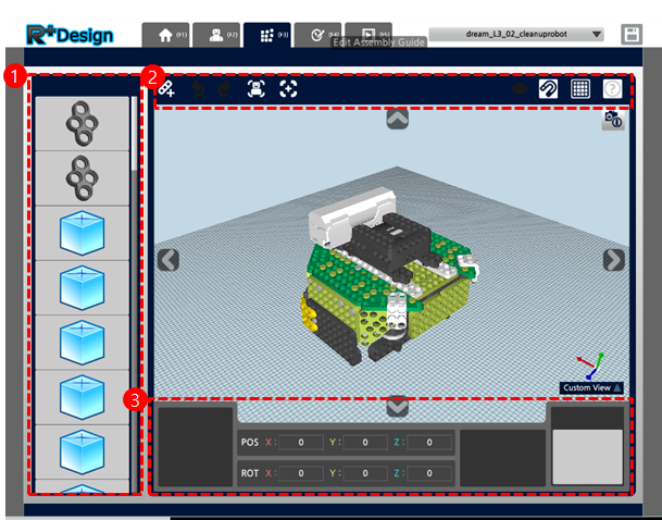
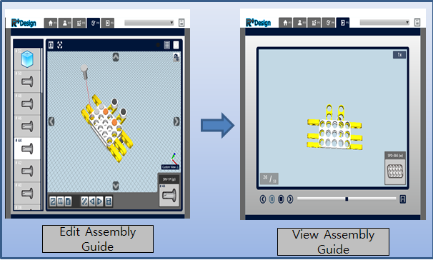
Edit Assembly Guide Tab
The Edit Assembly Guide tab lets users create and edit an assembly guide for a robot assembled in the Assembly Tab. A basic assembly guide is made automatically during the assembly, but using this tab a user can create or edit a more elaborate guide.
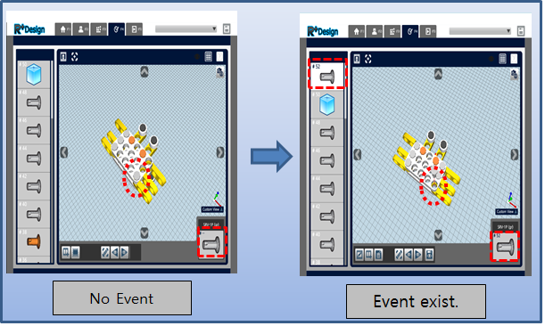
- Event list : A list that shows the events(move/hide) for each part (however, hide events are not shown in the list)
- Top bar : Delete all events, Move viewpoint to origin, grid On/Off, Help
- Bottom UI : Select Menu, Event(Part) Information
View Assembled Guide Tab
The View Assembly Guide tab allows user to view the entire process of assembling the robot.
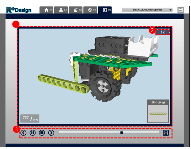
- Playback screen
- Display and change playback speed
- Operating buttons
Practice
Open Sample
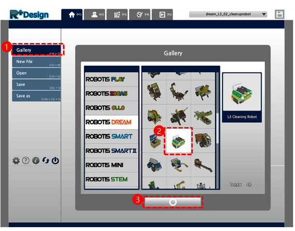
- Click on the “Gallery” tab button on the Home Tab
- Select a sample design file
- Click the “Confirm” button
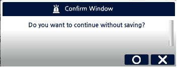
- If the robot currently being assembled was not saved, a confirmation window will appear.
Open Design File
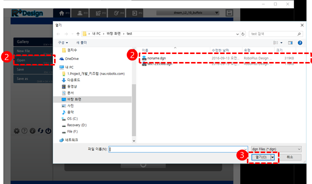
- Click the “Open” button on the Home tab,
- Select the design file you want to open in the file selection window.
- Click the “Open” button
- If the robot currently being assembled was not saved, a confirmation window will appear.
Create New Robot
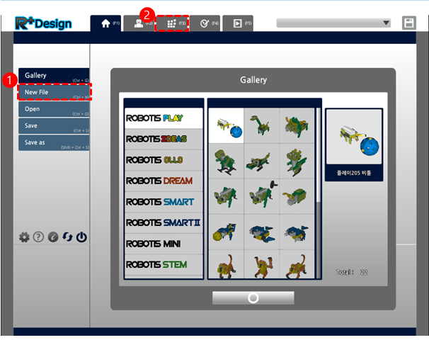
- Click the “New” button on the Home tab,
- If the robot currently being assembled was not saved, a confirmation window will appear.
- You can assemble the robot by moving on to the Assembly tab
Change Viewpoint
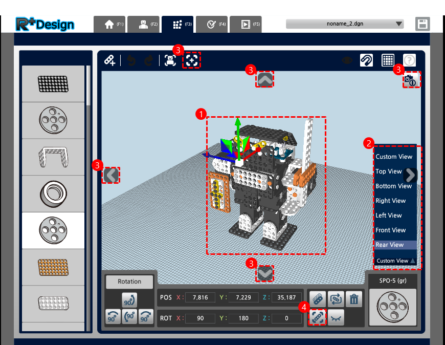
- Mouse
You can change the viewpoint by dragging the right button of the mouse,, and the current viewpoint can be seen by looking at the small figure(gizmo) in the bottom right corner. You can also use the mouse wheel to zoom in and out. If you right-click on a particular part, the viewpoint will change to show the part on the center of the screen: - Pop-up list
Use the pop-up list in the lower right corner to change to standard viewpoints. Selecting a viewpoint from the list will instantly change the display to that viewpoint. - Button
You can change the viewpoint using the arrow buttons at the top, bottom, left, and right. You can click the button on the top right corner to return to the default viewpoint, which can be set in My Robot Tab. By clicking the button at the top you can change the viewpoint to face the origin point.
(Origin point : The point that indicates the center of the virtual space in which the 3D robot is assembled, shown as a red dot on the screen.) - Part Menu
You can select a part and press the “Look At This” button or keyboard shortcut (F) to change the viewpoint so that the part is shown at center of the screen.
Adding Part
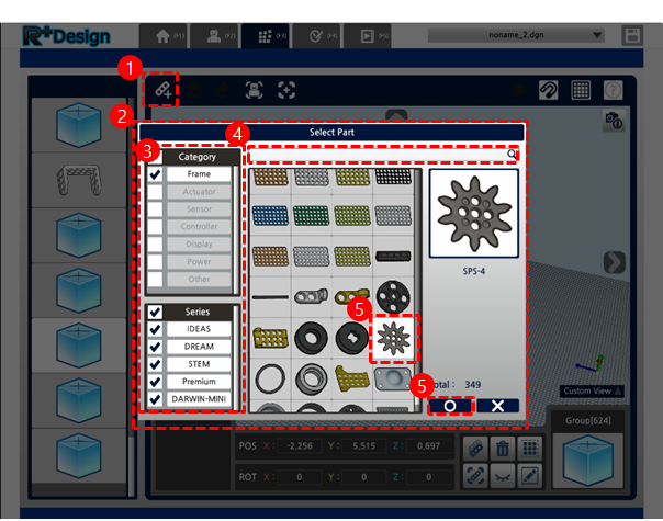
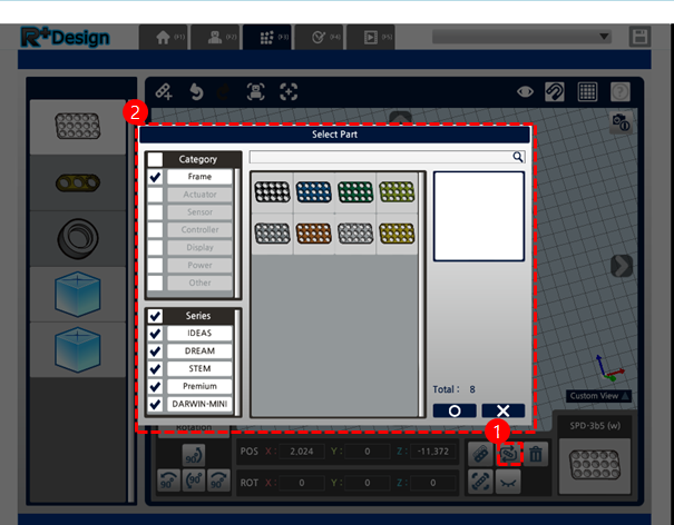
- Parts can be added by pressing the “Add Part” button at the top left corner or keyboard shortcut (P).
- When you press the button a Part Selection window will appear, which displays the category type on the top left, the series type on the bottom left, a search bar at the top, and the parts list on the center.
- You can easily find the part you wish to add by selecting or clearing the category and series check boxes on the left.
-
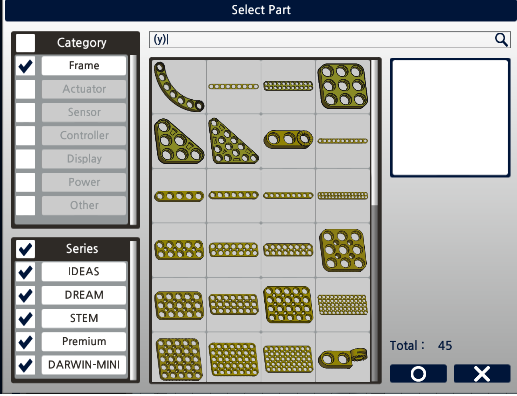
You can use the search bar at the top by typing in the part name. You can enter the full name of the part to search for it, but there are rules to the names that allow you to easily search parts according to their color or shape of plate. For example, if you want to search only yellow parts then typing “(y)” will show all the yellow parts on the screen; if you want to search only three-by-three shape plates then typing “3b3” will show all the corresponding shape plates on the screen.
- If you double-click an item on the list or select the item and press the Confirm button, then the selected part will be displayed in the 3D space. At this time the part will be following your mouse, so find an appropriate place for the part and click the left mouse button to place the part in the 3D space. If you have selected the wrong part then press the ESC key to cancel the selection.
Select Part
The 3D space
- In the 3D space you can left-click on a part to select it. The selected part will be shown with a yellow border.
- Selectable types are part, group, hole, port, connecting part, and cable, and with the exception of the port every other type can be selected multiple items at a time.
- You can select multiple items by pressing the Shift key while selecting different items or by dragging the 3D space to select all parts within the area.
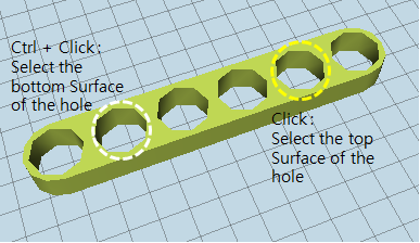
- For the holes, you get to select a surface so if you want to select the opposite surface you press Ctrl + click on a surface to select the opposite side. In this case, the surface of the hole you clicked on will be shown with a white border and the opposite side will be shown with a yellow border.
Part List
- A part can be selected by clicking from the parts list to the left, but the list only shows the parts and groups so using the parts list will only have these two options to choose from.
- Multiple selection of items is possible by using the Shift and Ctrl keys.
Deselect Part
- Pressing the ESC key or clicking on an empty area of the 3D space will cancel the selection of an item.
[Copying Part]
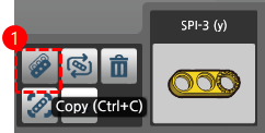
- Select a part and press the “Copy” button that appears on the bottom or the keyboard shortcut (Ctrl + C) to copy the part.
- When you copy a part a new copied item follows the mouse as when you have added a new part, and likewise pressing the ESC key will cancel the selection.
Change Part Color
- Select a part and press the “Change” button that appears on the bottom or the keyboard shortcut (C) to change the color of the part.
- If you press the button or keyboard shortcut then a part selection window will appear showing a list of items you can change.
Delete Part
Select the part you want to delete and press the “Delete” button that appears on the bottom or the keyboard shortcut (DEL) to delete the part.
Move Part
Using the Gizmo
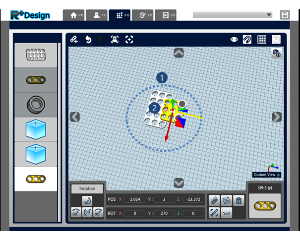
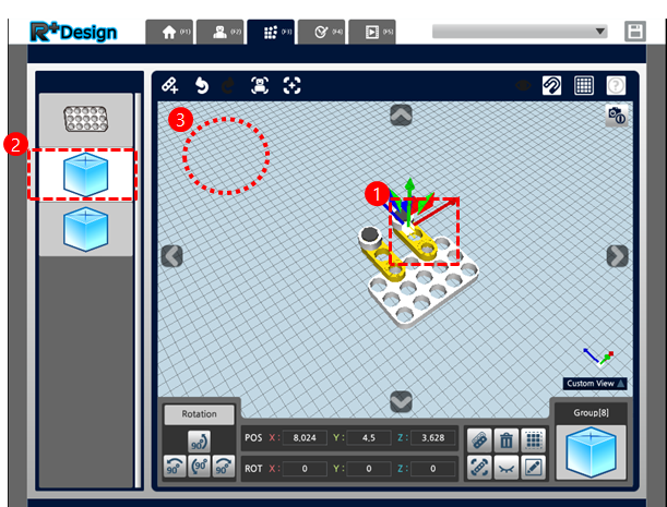
- You can use the gizmo that appears after you select a part in order to move the part. The gizmo consists of three axes and three surfaces, and you can drag each axis or surface in order to move the part in the direction that it points to.
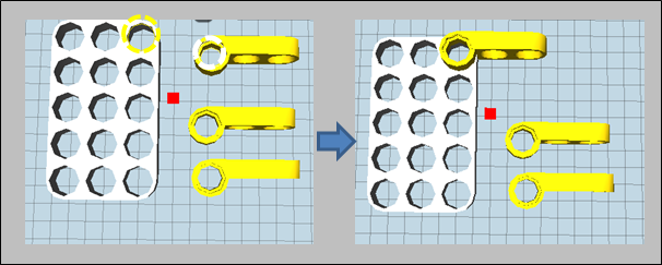
(Gizmo: The gizmo appears when you select a part for the purpose of helping you move or rotate the part. There is also a small gizmo at the bottom right corner of the screen with only the three axes, which represent the current viewpoint.) - Using the gizmo to move a part supports the auto-snap feature. When moving a part around, the auto-snap feature allows the part to automatically attach itself in respect to a hole or an axis to another nearby part. When the auto-snap feature is turned on, the holes to which the part can automatically attach to will be shown in red as in the image above.
- Once in a while there are occasions when you are moving a part around but the auto-snap feature will not be working well. In these cases, if the part has a distinguishable front-side and back-side you can flip the part around and move it in the opposite direction, or change the part that you are moving (B → A instead of A → B) in order to try and attach them more easily.
Hole-Based Move
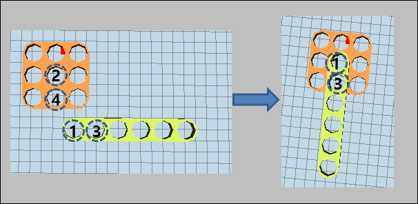
- The majority of times you will be moving a part in order to place a part’s hole to match another part’s hole, in which case it is convenient to use hole-based move.
- Hole-based move is done by selecting both the moving part’s hole and the hole you intend to match it to at the same time using multiple selection (Shift + click) and then pressing the “Hole-Based Move” button that appears on the bottom or the keyboard shortcut (M) in order to match the two holes.
-
Hole-based move can be done using 2 holes or 4 holes. When using 2 holes, the surface of the first hole selected will move to the surface of the second hole selected. When using 4 holes, choosing the right holes for the third hole and fourth hole is important because the third hole must be the same part as the first hole, and the fourth hole must be the same part as the second hole. So when using hole-based move with 4 holes, the surface of the first hole selected will move to the surface of the second hole selected, and the surface of the third hole selected will move to the surface of the fourth hole selected.
-
When selecting a hole it distinguishes the top and bottom surfaces, so it is important to choose the right hole when using hole-based move. Pressing on a hole will select the visible surface of the hole, so the part can get flipped when moving the part. If you wish to move the part without it rotating, you can select the opposite surface of the hole. (Selecting the opposite side of hole: Ctrl +Click)
Using the Bottom UI (Direct Input)
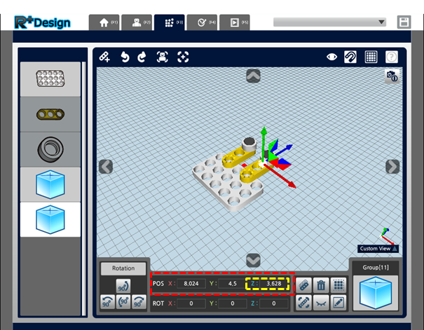
- When you select a part, the position(POS) and rotation(ROT) coordinates appear on the bottom, and the values can be modified directly in order to move or rotate the part.
- The bottom UI displays three axes which are in the same color as the axis that is represents in the gizmo. For example, if you want to move the part in the direction of the blue axis, you can change the value of the Z-axis shown in blue at the bottom UI.
CAUTION : When you move a part, only the selected part or the part containing the selected hole will move. Even if the part is connected to other parts using connecting parts(rivets, screws, etc.) it will still move separately, so if you wish to move multiple parts at once you much select them together (use gizmo) or create a group and then move the group.
Rotate Part
Using the Gizmo
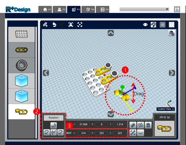
- When you select a part and the gizmo appears, pressing the Alt key will change the shape of the gizmo. Now drag the axis you want to rotate and the part will rotate around that axis.
- Once in a while there are occasions when the dragging does not work well depending on the viewpoint or direction, so regardless of the direction of the axis it is easier to drag the gizmo up and down.
Using the Rotation UI
When you select a part, the Rotation UI appears on the bottom and you can press the buttons on the UI or keyboard shortcuts “before(W) / after(S) / left(A) / right(D)” to rotate the part 90 degrees.
Using the Bottom UI (Direct Input)
- When you select a part, the rotation(ROT) coordinates appear on the bottom, and the values can be modified directly in order to rotate the part.
- For example, if you want to rotate the part around the red axis, you can change the value of the X-axis shown in red at the bottom UI.
Hole-Based Rotation
Using the Gizmo
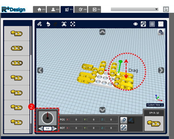
When you select a hole and press the Alt key a rotation gizmo appears, and dragging this gizmo will rotate the part around the selected hole.
Using the Rotation Slider
- If you select a hole the rotation slider appears on the bottom.
- You can rotate the part by moving the needle on the slider or by clicking the buttons at the bottom or putting in a value for the angle.
Connect Parts
Physical Connection (Rivets, Screws)
- Select a hole and press the “Attach” button that appears on the bottom or the keyboard shortcut (T) to connect to another part.
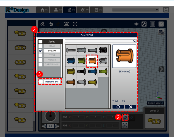
- If you press the button or keyboard shortcut then a part selection window will appear showing a list of connecting parts you can attach to the hole.
- The part selection window has an option called “Insert all the way in” on the left, and if you turn off this option then it will insert the connecting part only as deep as the hole’s depth and not all the way in.
- You can select many holes and add connecting parts to them at the same time.
Electrical Connection (Cable)
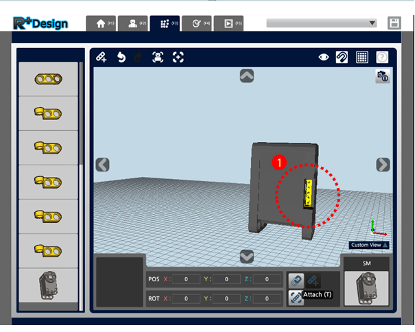
-
Select a port and press the “Attach” button that appears on the bottom or the keyboard shortcut (T) to connect parts electrically.
-
If you press the button or keyboard shortcut then a part selection window will appear showing a list of cables you can attach to the port.
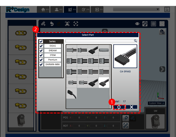
-
Multiple selection of ports is not supported.
Group
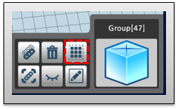
Creating a Group
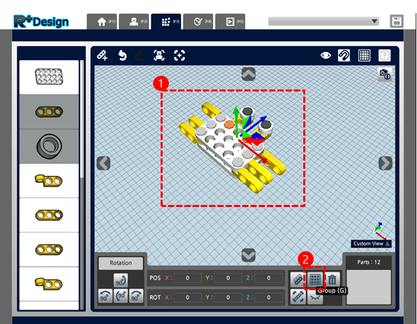
- Select multiple parts.
- Press the “Group” button at the bottom or the keyboard shortcut (G) to create a group.
- Parts that have been set as a group will move and rotate together as one part.
Editing a Group
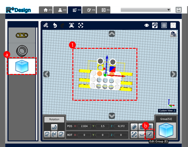
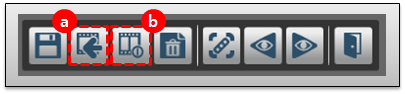
-
(a) Select a group and press the “Edit Group” button at the bottom or the keyboard shortcut (E) to enter the group editing mode, or (b) double-click the group icon on the left to enter the group edit mode.
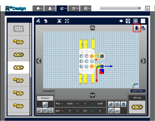
-
After you are finished editing, click the “Complete Editing” button to exit the group edit mode
Ungroup
Select a group and press the “Ungroup” button at the bottom or the keyboard shortcut (U) to break up a group.
Edit Robot Information
Robot Information
-
(a) Press the “Preview Capture” button to capture the preview image of a robot. The viewpoint during the capture will be the default viewpoint for the robot. (b) Before saving the preview, you can press the “Move to origin” button or select the robot (left-click) and move it using the gizmo to a position that you want.
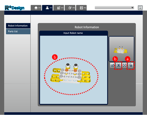
-
If you press the “Click to Edit” button a window will appear where you can edit the robot’s information. Here you can put in the robot’s name, author, etc.
Part List
The Parts List tab shows all the parts used in the robot. When actually making a robot you can easily view the parts you need. The can select multiple items in the Category list by pressing the Ctrl or Shift keys.
Edit Assembly Guide
Assembly Guide
- The Assembly Guide serves to visually demonstrate the assembling method of the robot assembled by the user. A basic assembly guide is made automatically during the assembly, but it is affected by the viewpoint or condition that was present during the assembly and may not create the Assembly Guide as the user intends it to. Therefore the Edit Assembly Guide tab allows the user to create or edit the guide.
-
Making the Assembly Guide is done by recording the process of disassembling the robot, so when the guide is actually played, it shows it in reverse order so you see the robot getting assembled.
- The Assembly Guide consists of the events of each part(part/group/connection part/ cable), and the two types of events are move events and hide events. Hide events are not shown in the event list on the left, and are usually created automatically when a move event is created.
Delete Event
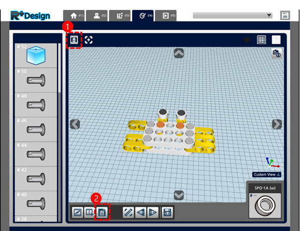
- Delete All Events : To delete all the events press the “Delete all events” button on the top.
- Delete Specific Event : Select an event and press the “Delete Event” button on the bottom or the keyboard shortcut (DEL) to delete the selected event.
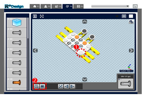
Select Part/Event
- When you select a part in 3D space, if the part already has events then the events will be selected together as well, and if it does not have an event then only the part will be selected.
- If only the part is selected, then you can add an event via the menu below. This event will be created next in order following whichever event was most recently selected.
- You can select an event from the event list on the left.
- However if there are two or more events for a part, then selecting a part in the 3D space may not select the event that you intend. In this case you should use the event list on the left.
- Selectable Parts : Part / Group / Connecting Part / Cable
Add Event
- Select a part without an event.
-
Press the “Add Move Event” or “Add Hide Event” buttons on the bottom.
- If you press the “Add Move Event” button a gizmo will appear which you can use to move/rotate the part.
- After moving/rotating a part, if you save the event then it will save the first position and last position of the part to create an event that moves in the opposite order as you just moved the part.
- Move events and hide events need to exist together, so when you save a move event if there is no hide event then it will create it automatically, and vice versa.
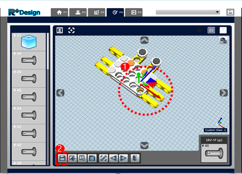
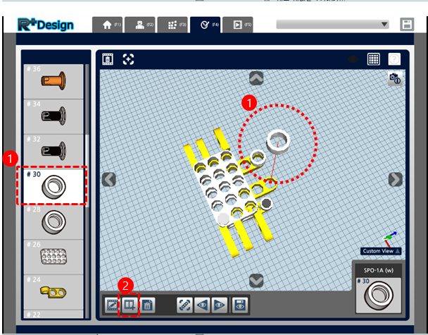
Edit Move Event
- To edit a move event, select the part for the event or select the event from the event list on the left.
- After selecting the event press the “Edit” button on the bottom or keyboard shortcut (E) to edit the event.
-
While editing you can (a) press the “Load Event” button to load the currently editing event again, or (b) press the “Reset Event” button to return to the initial position (the last position when playing the event).
- After you are finished editing press the “Save Event” button or the keyboard shortcut (V) to save the modified event.
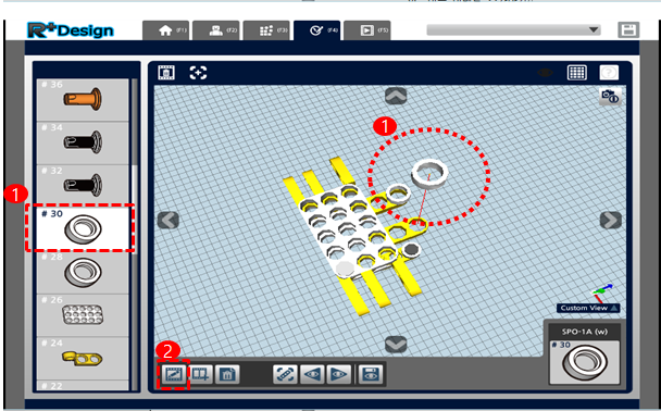
Add Move Event
- If you want to create multiple move events for one part, select an event and press the “Add Event” button on the bottom or the keyboard shortcut key (A).
- After adding move events, save the event.
Change Event Viewpoint
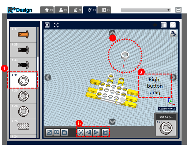
- If you want to simply change the viewpoint slightly, select the event and create a viewpoint that you would like to save.
- As in the Assembly Tab, you can (a) drag or click the right mouse button to change the viewpoint, or (b) use the “Align with previous viewpoint” or “Align with next viewpoint” buttons on the bottom to change the viewpoint.
- After you finish changing the viewpoint press the “Save View” button on the bottom or the keyboard shortcut (V) to save.
Install Instruction
Install on PC
-
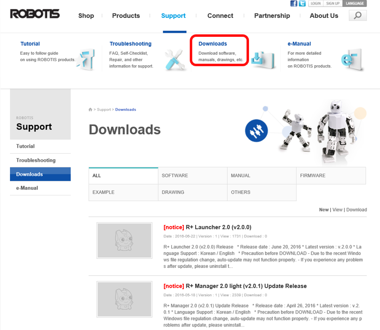
Click on “Downloads” after accessing to ROBOTIS website.
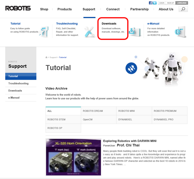
-
Search for the latest version of RoboPlus.
-
Click on “Download Link”.
-
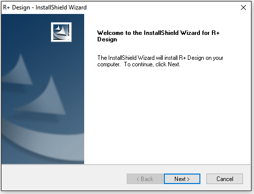
Install the downloaded file.
-
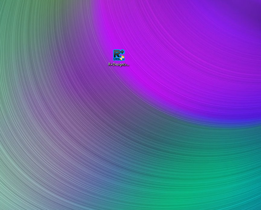
You will be able to see the R+Design icon once installment is done.
Install on Smartphone
Run “Play Store” or “App Store” and search for “ROBOTIS”.
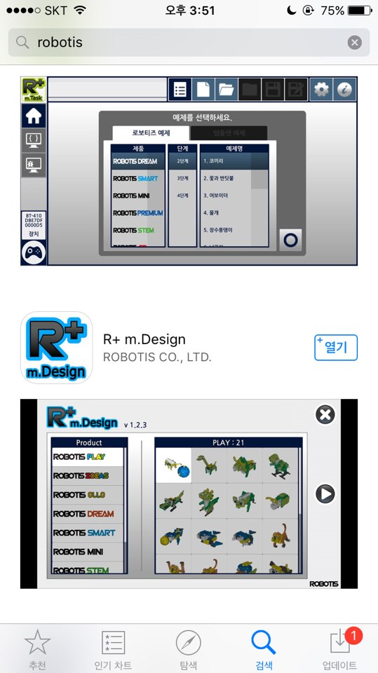
Install “R+m.Design”. You will be able to see the icon on the home screen.