Introduction
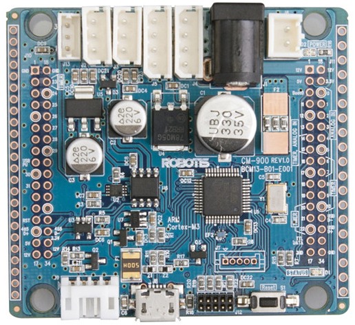
CM-900
- CM-900 is an embedded board based on STMicroelectronics’ STM32F103C8 Cortex-M3 MCU.
- The CM-900 hardware and software are open-source; support in Windows, Mac OSX, and Linux for convenient and easy development of robots
NOTE : CM-900 is discontinued.
Specifications
| Item | Description |
|---|---|
| CPU | STM32F103C8 (ARM Cortex-M3) |
| Operation Voltage | 5V~24V( USB 5V, DXL 12V, XL-Series 7.4V) |
| I/O | GPIO 32 |
| Timer | 4 ( 16bit ) |
| Analog In(ADC) | 10 ( 12bit ) |
| Flash | 64 Kbytes |
| SRAM | 20 Kbytes |
| Clock | 72Mhz |
| USB | 1 ( 2.0 FullSpeed ) |
| CAN | 1 |
| USART | 3 |
| SPI | 2 |
| I2C(TWI) | 2 |
| Debug | JTAG & SWD |
| DMA | 7ch |
| 3 Pin TTL | 2 |
| 4 Pin RS485 | 2 |
| 3 Pin XL-Serise | 1 |
| SIZE | 60mm X 54 mm X 1.6 mm |
- DYNAMIXEL’s cannot be driven from the USB power. Supply power for DYNAMIXEL separately (the CM-900’s power can be supplied from different sources).
- Check the voltage on the device’s power. DYNAMIXEL and XL series power voltage remain the same as supplied.
- DYNAMIXEL and XL-Series cannot be operated with differences in voltage.
Layout
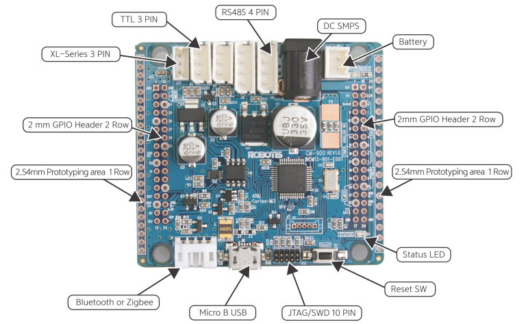
- Micro USB (type B) : provides the CM-900 with downloading and communication capabilities via PC, in addition to electrical power from USB’s 5V. Use the included USB cable or any other conventional USB cable you may likely have lying around.
- Reset switch : resets the CM-900 CPU.
- BT-110/ZIG-110 4PIN : Connect a 4-pin BT-110, BT-210, ZIG-110, or LN-101. This allows to communicate with external peripherals with serial UART communications. The LN-101 is more useful than simple firmware download from the PC.
- 2mm/2.54 mm prototyping area : located on both sides of the CM-900 board with 2.0mm or 2.54mm pitch to facilitate mounting of other devices.
- 2 mm GPIO Header : Allows the CM-900’s STM32F103C8 CPU to freely interfacewith external devices.
- TTL 3 PIN : connect to DYNAMIXEL via 3-pin cable daisy-chain (TTL communications).
- RS485 4 PIN : connect to DYNAMIXEL via 4-pin cable daisy-chain (RS-485 communications).
- Power LED : LED on when board is powered on and LED off when board is powered off.
- Status LED : CM-900’s program verification test LED. Send high/low signals to pin D16 to turn LED on/off.
- Battery socket : socket to connect battery.
- DC SMPS : jack for 12V SMPS.
- XL Series 3 PIN : Connect to DYNAMIXEL XL series via 3-pin TTL communications.
- JTAG/SWD 10 PIN : JTAG/SWD terminal for other programming features via IAR, Keil.
WARNING: To enhance user safety and to prevent proprietary risk or damage, be sure to check the pinout installed on DYNAMIXEL and the board. The Pinout of DYNAMIXEL may differ depending on a manufacturer of connector.
USB Driver Install
NOTE : There is no need to install drivers for Linux and Mac OS. Windows 8 startup settings : disable driver signature enforcement.
-
Driver installation ready after the CM-900 is connected to the PC via USB cable
-
Choose
ROBOTIS\driversdirectory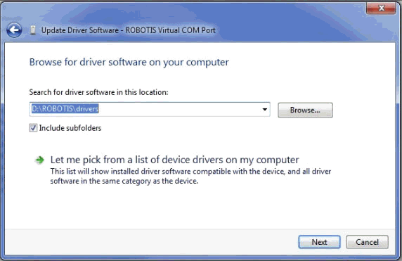
-
Choose “install this driver software anyways”
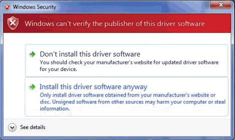
-
Check for COM port number
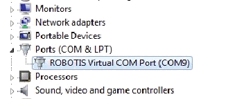
Instructions
-
Connect the CM-900 to the PC via USB cable
-
Double click on ROBOTIS CM-9.exe to start program
-
Go to “Tools” > “Serial Port” and select the correct port number(refer to Windows Device Manager)
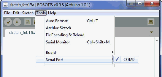
-
Select the corresponding hardware version
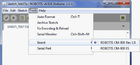
-
Pick any example
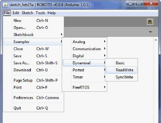
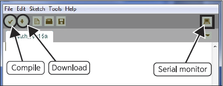
- Choose 1 of the 2buttons
- Check Button : compiles the code
- Download Button : compiles, and then downloads
- The examples are read-only
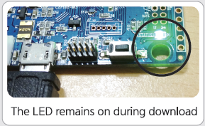
If Board is not responding appears (from Windows XP’s download) then update the USB Host Controller driver. Problems may occur if the driver version number is lower.
-
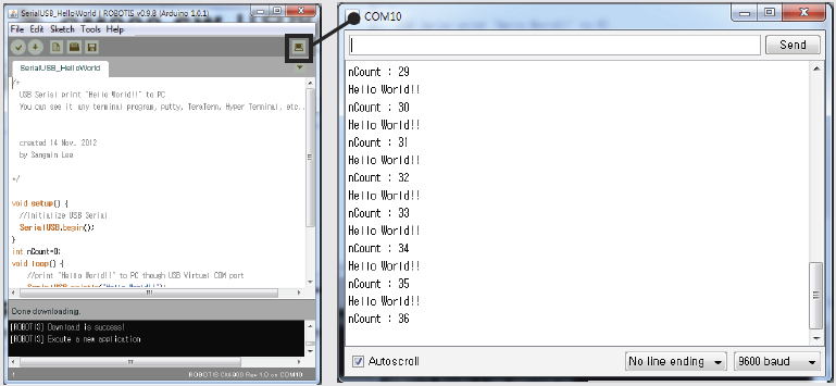
Check USB data via serial monitor
Downloads
The CM-900 uses the ROBOTIS CM-9 developmental environment to improve user experience. The IDE can be downloaded to match the OS being used; the link can be found below.
Download ZIPCM-900 Software for Windows XP, Vista, 7, 8Download ZIPCM-900 Software for OSX (tested with OS X 10.6.8)Download tarCM-900 Software for Linux 64bit (tested with Ubuntu 12.04)Download tarCM-900 Software for Linux 32bit (tested with Ubuntu 10.10)
References
Certifications
Please inquire us for information regarding unlisted certifications.
FCC
Note: This equipment has been tested and found to comply with the limits for a Class A digital device, pursuant to part 15 of the FCC Rules. These limits are designed to provide reasonable protection against harmful interference when the equipment is operated in a commercial environment. This equipment generates, uses, and can radiate radio frequency energy and, if not installed and used in accordance with the instruction manual, may cause harmful interference to radio communications. Operation of this equipment in a residential area is likely to cause harmful interference in which case the user will be required to correct the interference at his own expense.
WARNING
Any changes or modifications not expressly approved by the manufacturer could void the user’s authority to operate
the equipment.


