
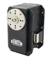
EX-106+
WARNING : EX-106+ has been discontinued.
Specifications
| Item | Specifications |
|---|---|
| Baud Rate | 7843 bps ~ 1 Mbps |
| Resolution | 0.06° |
| Running Degree | 0° ~ 251° Endless Turn |
| Weight | 154g |
| Dimensions (W x H x D) | 40.2mm x 65.1mm x 46mm |
| Gear Ratio | 184 : 1 |
| Stall Torque | 10.9 [N.m] (at 18.5V, 7A) |
| No Load Speed | 91rpm (at 18.5V) |
| Operating Temperature | -5°C ~ +80°C |
| Input Voltage | 12 ~ 18.5V (Recommended : 14.8V) |
| Command Signal | Digital Packet |
| Protocol Type | RS485 Asynchronous Serial Communication (8bit, 1stop, No Parity) |
| Physical Connection | RS485 Multi Drop Bus(Daisy Chain Type Connector) |
| ID | 0 ~ 253 |
| Feedback | Position, Temperature, Load, Input Voltage, etc |
| Material | Full Metal Gear, Aluminium Front Case, Engineering Plastic Body |
| Standby Current | 55mA |
NOTE : Stall torque is the maximum instantaneous and static torque. Stable motions are possible with robots designed for loads with 1/5 or less of the stall torque.
![]()
DANGER
(Ignoring these warnings may cause serious injury or death)
- Never place items containing water, flammables/open flames, or solvents near the product.
- Never place fingers, arms, toes, and other body parts near product during operation.
- Cease operation and remove power from the product if the product begins to emit strange odors, noises, or smoke.
- Keep product out of reach of children.
- Check input polarity before installing or energizing wiring or cables.
![]()
CAUTION
(Ignoring these warnings may cause mild injury or damage to the product)
- Always comply with the product’s offical operating environment specifications including input voltage, current, and operating temperature.
- Do not insert blades or other sharp objects during product operation.
![]()
ATTENTION
(Ignoring these warnings may cause minor injury or damage to the product)
- Do not disassemble or modify the product.
- Do not drop the product or apply strong impacts.
- Do not connect or disconnect DYNAMIXEL cables while power is being supplied.
Control Table
The Control Table is a data structure used by DYNAMIXEL actuators to manage the state of the device. Users can read data registers to get information about the status of the device with Read Instruction Packets, and modify data registers to control the device with Write Instruction Packets.
Control Table, Data, Address
The Control Table is a structure that consists of multiple Data fields to store status or to control the device. Users can check current status of the device by reading a specific Data from the Control Table with Read Instruction Packets. WRITE Instruction Packets enable users to control the device by changing specific Data in the Control Table. The Address is a unique value when accessing a specific Data in the Control Table with Instruction Packets. In order to read or write data, users must designate a specific Address in the Instruction Packet. Please refer to DYNAMIXEL Protocol 1.0 for more details about Instruction Packets.
Area (EEPROM, RAM)
The Control Table is divided into 2 Areas. Data in the RAM Area is reset to initial values when the power is reset(Volatile). On the other hand, data in the EEPROM Area is maintained even when the device is powered off(Non-Volatile).
Size
The Size of data varies from 1 ~ 2 bytes depend on their usage. Please check the size of data when updating the data with an Instruction Packet. For data larger than 2 bytes will be saved according to Little Endian.
Access
The Control Table has two different access properties. ‘RW’ property stands for read and write access permission while ‘R’ stands for read only access permission. Data with the read only property cannot be changed by the WRITE Instruction. Read only property(‘R’) is generally used for measuring and monitoring purpose, and read write property(‘RW’) is used for controlling device.
Initial Value
Each data in the Control Table is restored to initial values when the device is turned on. Default values in the EEPROM area are initial values of the device (factory default settings). If any values in the EEPROM area are modified by a user, modified values will be restored as initial values when the device is turned on. Initial Values in the RAM area are restored when the device is turned on.
Control Table of EEPROM Area
| Address | Size(Byte) | Data Name | Description | Access | Initial Value |
|---|---|---|---|---|---|
| 0 | 2 | Model Number | Model Number | R | 107 |
| 2 | 1 | Firmware Version | Firmware Version | R | - |
| 3 | 1 | ID | DYNAMIXEL ID | RW | 1 |
| 4 | 1 | Baud Rate | Communication Speed | RW | 34 |
| 5 | 1 | Return Delay Time | Response Delay Time | RW | 250 |
| 6 | 2 | CW Angle Limit | Clockwise Angle Limit | RW | 0 |
| 8 | 2 | CCW Angle Limit | Counter-Clockwise Angle Limit | RW | 4,095 |
| 10 | 1 | Drive Mode | Dual Mode Setting | RW | 0 |
| 11 | 1 | Temperature Limit | Maximum Internal Temperature Limit | RW | 80 |
| 12 | 1 | Min Voltage Limit | Minimum Input Voltage Limit | RW | 60 |
| 13 | 1 | Max Voltage Limit | Maximum Input Voltage Limit | RW | 240 |
| 14 | 2 | Max Torque | Maximun Torque | RW | 1023 |
| 16 | 1 | Status Return Level | Select Types of Status Return | RW | 2 |
| 17 | 1 | Alarm LED | LED for Alarm | RW | 36 |
| 18 | 1 | Shutdown | Shutdown Error Information | RW | 36 |
Control Table of RAM Area
| Address | Size(Byte) | Data Name | Description | Access | Initial Value |
|---|---|---|---|---|---|
| 24 | 1 | Torque Enable | Motor Torque On/Off | RW | 0 |
| 25 | 1 | LED | Status LED On/Off | RW | 0 |
| 26 | 1 | CW Compliance Margin | CW Compliance Margin | RW | 1 |
| 27 | 1 | CCW Compliance Margin | CCW Compliance Margin | RW | 1 |
| 28 | 1 | CW Compliance Slope | CW Compliance Slope | RW | 32 |
| 29 | 1 | CCW Compliance Slope | CCW Compliance Slope | RW | 32 |
| 30 | 2 | Goal Position | Target Position | RW | - |
| 32 | 2 | Moving Speed | Moving Speed | RW | - |
| 34 | 2 | Torque Limit | Torque Limit | RW | Max Torque |
| 36 | 2 | Present Position | Present Position | R | - |
| 38 | 2 | Present Speed | Present Speed | R | - |
| 40 | 2 | Present Load | Present Load | R | - |
| 42 | 1 | Present Voltage | Present Voltage | R | - |
| 43 | 1 | Present Temperature | Present Temperature | R | - |
| 44 | 1 | Registered | If Instruction is registered | R | 0 |
| 46 | 1 | Moving | Movement Status | R | 0 |
| 47 | 1 | Lock | Locking EEPROM | RW | 0 |
| 48 | 2 | Punch | Minimum Current Threshold | RW | 0 |
| 56 | 2 | Sensed Current | Consuming Current | R | - |
Control Table Description
Model Number (0)
This address stores model number of DYNAMIXEL.
Firmware Version (2)
This address stores firmware version of DYNAMIXEL.
ID (3)
The ID is a unique value in the network to identify each DYNAMIXEL with an Instruction Packet. 0~253 (0xFD) values can be used as an ID, and 254(0xFE) is occupied as a broadcast ID. The Broadcast ID(254, 0xFE) can send an Instruction Packet to all connected DYNAMIXEL’s simultaneously.
NOTE : Please avoid using an identical ID for multiple DYNAMIXEL’s. You may face communication failure or may not be able to detect DYNAMIXEL’s with an identical ID.
Baud Rate (4)
Baud Rate determines serial communication speed between a controller and DYNAMIXEL’s.
| Value | Baud Rate | Margin of Error |
|---|---|---|
| 1 | 1M | 0.000% |
| 3 | 500,000 | 0.000% |
| 4 | 400,000 | 0.000% |
| 7 | 250,000 | 0.000% |
| 9 | 200,000 | 0.000% |
| 16 | 115200 | -2.124% |
| 34(Default) | 57600 | 0.794% |
| 103 | 19200 | -0.160% |
| 207 | 9600 | -0.160% |
NOTE : Less than 3% of the baud rate error margin will not affect to UART communication.
NOTE : For the stable communication with higher baudrate, configure USB Latency value to the lower. USB Latency Setting
Return Delay Time (5)
After DYNAMIXEL receives an Instruction Packet, it delays transmitting the Status Packet for Return Delay Time (9). For instance, if the Return Delay Time(9) is set to ‘10’, the Status Packet will be returned after 20[μsec] when the Instruction Packet is received.
| Value | Description | |
|---|---|---|
| Unit | 2[μsec] | - |
| Range | 0 ~ 254 | Default value ‘250’(500[μsec]), Maximum 508[μsec] |
CW/CCW Angle Limit (6, 8)
The angle limit allows the motion to be restrained. The range and the unit of the value is the same as Goal Position(Address 30, 31). CW Angle Limit: the minimum value of Goal Position(Address 30, 31) CCW Angle Limit: the maximum value of Goal Position(Address 30, 31) The following two modes can be set pursuant to the value of CW and CCW.
| Operation Type | CW / CCW |
|---|---|
| Wheel Mode | both are 0 |
| Joint Mode | neither are 0 |
The wheel mode can be used to wheel-type operation robots since motors of the robots spin infinitely. The joint mode can be used to multi-joints robot since the robots can be controlled with specific angles.
Drive Mode (10)
The Drive Mode(10) configures Drive Mode of DYNAMIXEL.
| Bit | Item | Description | ||
|---|---|---|---|---|
| Bit 7(0x80) | - | Unused, always ‘0’ | ||
| Bit 6(0x40) | - | Unused, always ‘0’ | ||
| Bit 5(0x20) | - | Unused, always ‘0’ | ||
| Bit 4(0x10) | - | Unused, always ‘0’ | ||
| Bit 3(0x08) | - | Unused, always ‘0’ | ||
| Bit 2(0x04) | - | Unused, always ‘0’ | ||
| Bit 1(0x02) | Master/Slave Mode (Dual Joint) |
[0] Master Mode: Operate as a Master DYNAMIXEL. [1] Slave Mode: Operate as Slave DYNAMIXEL |
||
| Bit 0(0x01) | Normal/Reverse Mode | [0] Normal Mode: CCW(Positive), CW(Negative) [1] Reverse Mode: CCW(Negative), CW(Positive) |
NOTE : If the value of Bit 0(Normal/Reverse Mode) of the Drive Mode(10) is set to 1, rotational direction is inverted.
Thus, Goal Position, Present Position will have a inverted direction.
This feature can be very useful when configuring symmetrical joint.
CAUTION : When MX-106 and EX-106+ are set to Wheel Mode(endless), Normal/Reverse Mode is not available.
Normal/Reverse Mode is activated under Joint Mode and Multi-turn Mode.
Please refer to CW/CCW Angle Limit for configuring Operation Type.
Dual Mode
Dual Mode is intended to combine two DYNAMIXEL into a single joint to enhance the performance.
In order to use Dual Mode, Slave DYNAMIXEL should be connected to Master DYNAMIXEL with the Sync Cable.
Please note that the Slave DYNAMIXEL is directly controlled only by the PWM signal from the Master DYNAMIXEL through the Sync Cable.
Thus, Goal Position, Moving Speed of the Slave DYNAMIXEL are unused and ignored.
The rotational direction of Slave DYNAMIXEL is decided by the type of Sync Cable rather than the Normal/Reverse Mode setting of Slave DYNAMIXEL.
The twisted sync cable will actuate the Slave DYNAMIXEL to the opposite direction of the Master DYNAMIXEL while regular sync cable actuate to the same direction.
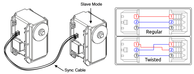
| Sync Cable | Description |
|---|---|
| Regular Sync Cable | Slave DYNAMIXEL is controlled by the PWM Signal from the Master DYNAMIXEL.Master and Slave DYNAMIXEL rotate in the same direction. |
| Twisted Sync Cable | Slave DYNAMIXEL is controlled by the Inverted PWM Signal from the Master DYNAMIXEL.Master and Slave DYNAMIXEL rotate in the opposite direction. |
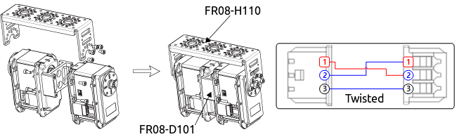
CAUTION : If Master and Slave are not physically connected by frame, both DYNAMIXEL may not perfectly synchronized due to the load applied on each DYNAMIXEL.
Please use appropriate frame to connect DYNAMIXEL in Dual Mode.
Temperature Limit (11)
CAUTION : Do not set the temperature lower/higher than the default value. When the temperature alarm shutdown occurs, wait 20 minutes to cool the temperature before re-use. Using the product when the temperature is high may and can cause damage.
Min/Max Voltage Limit (12, 13)
It is the operation range of voltage.
| Unit | Value Range | Description |
|---|---|---|
| About 0.1V | 50 ~ 250 | 5.0 ~ 25.0V |
For example, if the value is 80, the voltage is 8V. If Present Voltage(42) is out of the range, Voltage Range Error Bit (Bit0) of Status Packet is returned as ‘1’ and Alarm is triggered as set in the addresses 17 and 18.
Max Torque (14)
It is the torque value of maximum output. 0 to 1023 (0x3FF) can be used, and the unit is about 0.1%. For example, Data 1023 (0x3FF) means that DYNAMIXEL will use 100% of the maximum torque it can produce while Data 512 (0x200) means that DYNAMIXEL will use 50% of the maximum torque. When the power is turned on, Torque Limit (Addresses 34 and 35) uses the value as the initial value.
Status Return Level (16)
It decides how to return Status Packet. There are three ways like the below table.
| Value | Return of Status Packet |
|---|---|
| 0 | No return against all commands (Except PING Command) |
| 1 | Return only for the READ command |
| 2 | Return for all commands |
When Instruction Packet is Broadcast ID, Status Packet is not returned regardless of Status Return Level.
Alarm LED(17), Shutdown(18)
The DYNAMIXEL can protect itself by detecting dangerous situations that could occur during the operation. Each Bit is inclusively processed with the ‘OR’ logic, therefore, multiple options can be generated. For instance, when ‘0x05’ (binary : 00000101) is defined in Shutdown(18), DYNAMIXEL can detect both Input Voltage Error(binary : 00000001) and Overheating Error(binary : 00000100). If those errors are detected, the Alarm LED will start blinking and the motor’s output will be 0 [%].
The followings are detectable situations.
| Bit | Item | Description |
|---|---|---|
| Bit 7 | 0 | - |
| Bit 6 | Instruction Error | Detects that undefined Instruction is transmitted or the ACTION command is delivered without the REG_WRITE command |
| Bit 5 | Overload Error | Detects that persistent load exceeds maximum output |
| Bit 4 | CheckSum Error | Detects that the Checksum of the transmitted Instruction Packet is invalid |
| Bit 3 | Range Error | Detects that the command is given beyond the range of usage |
| Bit 2 | Overheating Error | Detects that the internal temperature exceeds the set temperature |
| Bit 1 | Angle Limit Error | Detects that Goal Position is written with the value that is not between CW Angle Limit and CCW Angle Limit |
| Bit 0 | Input Voltage Error | Detects that input voltage exceeds the configured operating voltage |
NOTE : If Shutdown occurs, LED will flicker every second.
Torque Enable (24)
| Value | Description |
|---|---|
| 0 | Keeps Torque from generating by interrupting the power of motor |
| 1 | Generates Torque by impressing the power to the motor. |
LED (25)
| Bit | Description |
|---|---|
| 0 | Turn OFF the LED |
| 1 | Turn ON the LED |
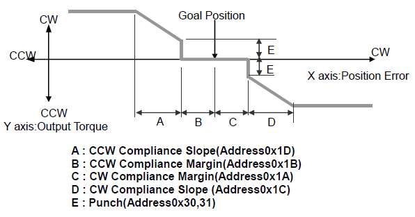
Compliance Margin (26, 27)
It exists in each direction of CW/CCW and means the error between goal position and present position. The range of the value is 0~255, and the unit is the same as Goal Position.(Address 30,31) The greater the value, the more difference occurs.
Compliance Slope (28, 29)
It exists in each direction of CW/CCW and sets the level of Torque near the goal position. Compliance Slope is set in 7 steps, the higher the value, the more flexibility is obtained. Data representative value is actually used value. That is, even if the value is set to 25, 16 is used internally as the representative value.
| Step | Data Value | Data Representative Value |
|---|---|---|
| 1 | 0(0x00) ~ 3(0x03) | 2(0x02) |
| 2 | 4(0x04) ~ 7(0x07) | 4(0x04) |
| 3 | 8(0x08)~15(0x0F) | 8(0x08) |
| 4 | 16(0x10)~31(0x1F) | 16(0x10) |
| 5 | 32(0x20)~63(0x3F) | 32(0x20) |
| 6 | 64(0x40)~127(0x7F) | 64(0x40) |
| 7 | 128(0x80)~254(0xFE) | 128(0x80) |
Compliance is to set the control flexibility of the motor. The following diagram shows the relationship between output torque and position of the motor.
Goal Position (30)
Set the DYNAMIXEL’s goal position through the Goal Position(30). 0 to 1023 (0x3FF) is available. The unit is 0.29 degree. If Goal Position is out of the range, Angle Limit Error Bit (Bit1) of Status Packet is returned as ‘1’ and Alarm is triggered as set in Alarm LED/Shutdown.
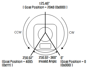 The picture above is the front view of DYNAMIXEL
NOTE : If it is set to Wheel Mode, this value is not used.
Moving Speed (32)
It is a moving speed to Goal Position. The range and the unit of the value may vary depending on the operation mode.
-
Join Mode 0~1023 (0X3FF) can be used, and the unit is about 0.111rpm. If it is set to 0, it means the maximum rpm of the motor is used without controlling the speed. If it is 1023, it is about 114rpm. For example, if it is set to 300, it is about 33.3 rpm.
-
Wheel Mode 0~2047( 0X7FF) can be used, the unit is about 0.1%. If a value in the range of 0~1023 is used, it is stopped by setting to 0 while rotating to CCW direction. If a value in the range of 1024~2047 is used, it is stopped by setting to 1024 while rotating to CW direction. That is, the 10th bit becomes the direction bit to control the direction. In Wheel Mode, only the output control is possible, not speed. For example, if it is set to 512, it means the output is controlled by 50% of the maximum output.
NOTE : Please check the maximum rpm of DYNAMIXEL. The motor cannot exceed the maximum rpm with the higher Moving Speed value.
Torque Limit (34)
It is the value of the maximum torque limit. 0 to 1023 (0x3FF) is available, and the unit is about 0.1%. For example, if the value is 512, it is about 50%; that means only 50% of the maximum torque will be used. If the power is turned on, the value of Max Torque (Address 14, 15) is used as the initial value.
NOTE : If the function of Alarm Shutdown is triggered, the motor loses its torque because the value becomes 0. At this moment, if the value is changed to the value other than 0, the motor can be used again.
Present Position (36)
It is the current position value of DYNAMIXEL. The range of the value is 0~1023 (0x3FF), and the unit is 0.29 degree.
The picture above is the front view of DYNAMIXEL.
-
Wheel Mode The range of the value is 0~65535(0XFFFF), and the unit is 0.06 degree. In case of Wheel Mode, only the moving distance can be measured since the present location outputs the value of Encoder. It is increased or decreased by 1 depending on the moving direction of wheel. If it is decreased when the value is 0, it becomes 65535; if it is increased when it is 65535, the value becomes 0.
Total Moved Angle = (The value currently measured - The value measured in the past) x 0.06 According to the formula above, if the total moved angle is greater than 0, it is turned to the direction of CCW; if it is less than 0, it is turned to the direction of CW. For example, The value is changed from 5000 to 10000, (10000 - 5000) x 0.06 = 300, and the total moved angle becomes 300 degrees.
Present Speed (38)
It is the current moving speed. 0~2047 (0X7FF) can be used. If a value is in the rage of 0~1023, it means that the motor rotates to the CCW direction. If a value is in the rage of 1024~2047, it means that the motor rotates to the CW direction. That is, the 10th bit becomes the direction bit to control the direction, and 0 and 1024 are equal. The unit of this value varies depending on operation mode.
-
Joint Mode The unit is about 0.111rpm. For example, if it is set to 300, it means that the motor is moving to the CCW direction at a rate of about 33.3rpm.
-
Wheel Mode The unit is about 0.1%. For example, if it is set to 512, it means that the torque is controlled by 50% of the maximum torque to the CCW direction.
Present Load (40)
It means currently applied load. The range of the value is 0~2047, and the unit is about 0.1%. If the value is 0~1023, it means the load works to the CCW direction. If the value is 1024~2047, it means the load works to the CW direction. That is, the 10th bit becomes the direction bit to control the direction, and 1024 is equal to 0. For example, the value is 512, it means the load is detected in the direction of CCW about 50% of the maximum torque.
| Bit | 15 ~ 11 | 10 | 9 ~ 0 |
|---|---|---|---|
| Value | 0 | Load Direction | Data (Load Ratio) |
NOTE : CCW Load : Load Direction = 0, CW Load : Load Direction = 1
NOTE : Present load is an inferred value based on the internal output value; not a measured value using torque sensor, etc. Therefore, it may be inaccurate for measuring weight or torque. It is recommended to use it for predicting the direction and size of the force being applied to the joint.
Present Voltage (42)
It is the size of the current voltage supplied. This value is 10 times larger than the actual voltage. For example, when 10V is supplied, the data value is 100 (0x64)
Present Temperature (43)
It is the internal temperature of DYNAMIXEL in Celsius. Data value is identical to the actual temperature in Celsius. For example, if the data value is 85 (0x55), the current internal temperature is 85°C.
Registered Instruction (44)
| Value | Description |
|---|---|
| 0 | There are no commands transmitted by REG_WRITE |
| 1 | There are commands transmitted by REG_WRITE |
NOTE : If ACTION command is executed, the value is changed into 0.
Moving (46)
| Value | Description |
|---|---|
| 0 | Goal position command execution is completed |
| 1 | Goal position command execution is in progress |
Lock (47)
| Value | Description |
|---|---|
| 0 | EEPROM area can be modified |
| 1 | EEPROM area cannot be modified |
CAUTION : If Lock is set to 1, the power must be turned off and then turned on again to change into 0.
Punch (48)
Current to drive motor is at minimum. Can choose vales from 0x20 to 0x3FF.
Sensed Current (56)
It is the amount of current in use. The range from 0 to 1023 is used, and the unit is 10mA. The value less than 512 means the motor consumes the current and torques to the direction of CCW. The value greater than 512 means the motor consumes the current and torques to the direction of CW. 512 is equal to 0mA, and it means there is no torque from the motor.
For example, if the value is 612, the motor torques to the direction of CW and consumes 1000mA(612-512=100 => 100x10mA = 1,000mA).
If the value is 312, the motor torques to the direction of CW and consumes 2000mA(512-312= -200 => 200x10mA=2,000mA).
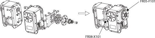
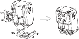
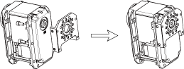
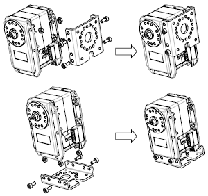
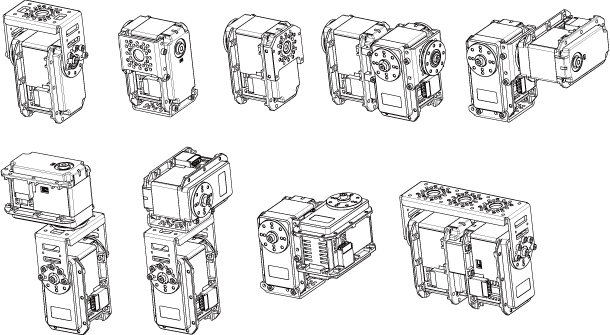
How to Assemble
Optional Frames
-
FR05-F101 and FR08-X101
-
FR05-S101
-
FR08-B101
-
FR08-H101
-
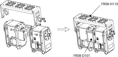
FR08-H110 and FR08-D101
-
FR05-S1 Option Frame
Horns
-
HN05-N102

-
HN05-I101
-
HN05-T101 Horn
-
HN05-N1 Horn
-
HN05-T1 Horn
-
HN05-I1 Horn
Combination Structures
Maintenance
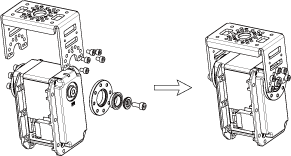
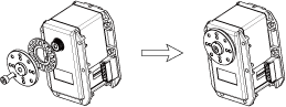
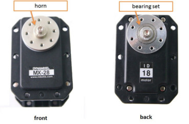
Horn and Bearing Replacement
The horn is installed on the front wheel gear serration of the DYNAMIXEL whereas the bearing set is installed on the back.
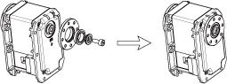
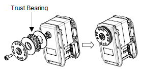
Installing the Horn
Place the thrust horn washer into the actuator before inserting the horn. You must carefully align the horn to the wheel gear serration by aligning dots.
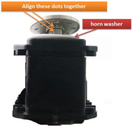
Once alignment is properly done, gently push the center of the horn toward the actuator. Make sure that the horn washer is in place as you tighten the bolt.
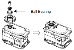
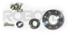
Installing the Bearing Set
You may need to remove the bearing set from the previous actuator and reinstall it into the new actuator. The bearing set can also be purchased separately. As bearing set is rotating freely, therefore alignment is not required when assembling to DYNAMIXEL.
Reference
NOTE : Compatibility Guide
Connector Information
| Item | RS-485 |
|---|---|
| Pinout | 1 GND2 VDD3 DATA+4 DATA- |
| Diagram |  |
| Housing | 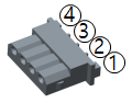 MOLEX 50-37-5043 |
| PCB Header | 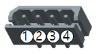 MOLEX 22-03-5045 |
| Crimp Terminal | MOLEX 08-70-1039 |
| Wire Gauge for DYNAMIXEL | 21 AWG |
WARNING: To enhance user safety and to prevent proprietary risk or damage, be sure to check the pinout installed on DYNAMIXEL and the board. The Pinout of DYNAMIXEL may differ depending on a manufacturer of connector.
Drawings
DownloadEX-106R DWGDownloadEX-106R PDFDownloadEX-106R STEPDownloadEX-106R IGES
Communication Circuit
To control the DYNAMIXEL actuators, the main controller needs to convert its UART signals to the half duplex type. The recommended circuit diagram for this is shown below.
TTL Communication
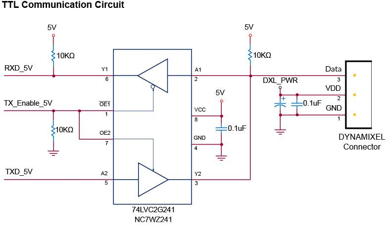
NOTE: Above circuit is designed for 5V or 5V tolerant MCU. Otherwise, use a Level Shifter to match the voltage of MCU.
RS-485 Communication
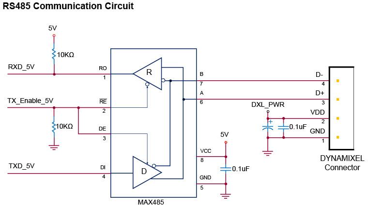
NOTE: Above circuit is designed for 5V or 5V tolerant MCU. Otherwise, use a Level Shifter to match the voltage of MCU.
The power of DYNAMIXEL is supplied via Pin1(-), Pin2(+).
(The above circuit is built into DYNAMIXEL’s controller only)
In the above circuit diagram, the direction of data signal of TxD and RxD in the TTL Level is determined according to the level of TX_Enable_5V as follows:
In case of TX_Enable_5V = High: The signal of TxD is output to D+ and D-
In case of TX_Enable_5V = Low: The signal of D+ and D- is output to RxD
Please also checkout ROBOTIS Download Center for software applications, 3D/2D CAD, and other useful resources!
Communication Circuit
To control the DYNAMIXEL actuators, the main controller needs to convert its UART signals to the half duplex type. The recommended circuit diagram for this is shown below.
TTL Communication
NOTE: Above circuit is designed for 5V or 5V tolerant MCU. Otherwise, use a Level Shifter to match the voltage of MCU.
RS-485 Communication
NOTE: Above circuit is designed for 5V or 5V tolerant MCU. Otherwise, use a Level Shifter to match the voltage of MCU.
The power of DYNAMIXEL is supplied via Pin1(-), Pin2(+).
(The above circuit is built into DYNAMIXEL’s controller only)
In the above circuit diagram, the direction of data signal of TxD and RxD in the TTL Level is determined according to the level of TX_Enable_5V as follows:
In case of TX_Enable_5V = High: The signal of TxD is output to D+ and D-
In case of TX_Enable_5V = Low: The signal of D+ and D- is output to RxD