Communication Overview
To control DYNAMIXEL, communication should be established according to the protocol of DYNAMIXEL. DYNAMIXEL is driven by receiving binary data. Examples of programs for the transmission of this kind of data are described in detail in the User’s Manual of DYNAMIXEL-only controller or the USB2DYNAMIXEL. Thus, this manual describes only the method and protocol of communication used in DYNAMIXEL on the assumption that Main Controller can transfer binary data.
TIP : Users can refer to ROBOTIS’s DYNAMIXEL Protocol Compatibility Table with reference.
Packet
Main Controller and DYNAMIXEL communicate each other by sending and receiving data called Packet. Packet has two kinds: Instruction Packet, which Main Controller sends to control DYNAMIXEL, and Status Packet, which DYNAMIXEL responses to Main Controller.
ID
ID is a specific number for distinction of each DYNAMIXEL when several DYNAMIXEL’s are linked to one bus. By giving IDs to Instruction and Status Packets, Main Controller can control only DYNAMIXEL that you want to control
DYNAMIXEL Protocol
DYNAMIXEL does the Asynchronous Serial Communication with 8 bit, 1 Stop bit, and None Parity.
If DYNAMIXEL with the same ID is connected, packet will collide and network problem will occur. Thus, set ID as such that there is no DYNAMIXEL with the same ID. To change the DYNAMIXEL’s ID, reference the DYNAMIXEL Control Table section in the DYNAMIXEL Wizard 2.0.
NOTE: The DYNAMIXEL’s initial ID is 1 at the factory condition.
Half Duplex
Half duplex UART is a serial communication protocol where both TxD and RxD cannot be used at the same time. This method is generally used when many devices need to be connected to a single bus. Since more than one device are connected to the same bus, all the other devices need to be in input mode while one device is transmitting. The Main Controller that controllers DYNAMIXEL actuators sets the communication direction to input mode, and only when it is transmitting an Instruction Packet, it changes the direction to output mode.
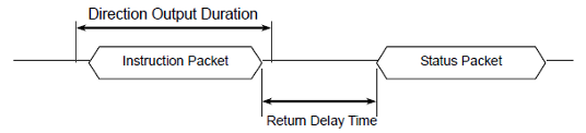
Tx, Rx Direction
For Half Duplex UART, the transmission ending timing is important to change the direction to receiving mode. The bit definitions within the register that indicates UART_STATUS are as the following
- TXD_BUFFER_READY_BIT: Indicates that the transmission DATA can be loaded into the Buffer. Note that this only means that the SERIAL TX BUFFER is empty, and does not necessarily mean that the all the data transmitted before has left the CPU.
- TXD_SHIFT_REGISTER_EMPTY_BIT: Set when all the Transmission Data has completed its transmission and left the CPU.
The TXD_BUFFER_READY_BIT is used when one byte is to be transmitted via the serial communication channel, and an example is shown below.
  TxDByte(byte bData)
  {
    while(!TXD_BUFFER_READY_BIT); //wait until data can be loaded.
    SerialTxDBuffer = bData; //data load to TxD buffer
  }
When changing the direction, the TXD_SHIFT_REGISTER_EMPTY_BIT must be checked. The following is an example program that sends an Instruction Packet
DIRECTION_PORT = TX_DIRECTION;
TxDByte(0xff);
TxDByte(0xff);
TxDByte(bID);
TxDByte(bLength);
TxDByte(bInstruction);
TxDByte(Parameter0); TxDByte(Parameter1); ...
DisableInterrupt(); // interrupt should be disable
TxDByte(Checksum); //last TxD
while(!TXD_SHIFT_REGISTER_EMPTY_BIT); //Wait till last data bit has been sent
DIRECTION_PORT = RX_DIRECTION; //Direction change to RXD
EnableInterrupt(); // enable interrupt again
WARNING : Please note the important lines between LINE 8 and LINE 12. Line 8 is necessary since an interrupt here may cause a delay longer than the return delay time and corruption to the front of the status packet may occur.
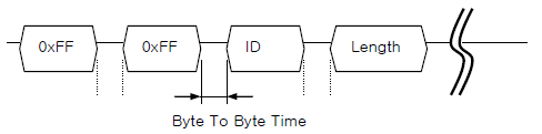
Byte to Byte Time
The delay time between bytes when sending an instruction packet. If the delay time is over 100ms, then DYNAMIXEL actuator recognizes this as a communication problem and waits for the next header (0xff 0xff) of a packet again.
Instruction Packet
Instruction Packet is the command data sent to the Device.
| Header1 | Header2 | Packet ID | Length | Instruction | Param 1 | … | Param N | Checksum |
|---|---|---|---|---|---|---|---|---|
| 0xFF | 0xFF | Packet ID | Length | Instruction | Param 1 | … | Param N | CHKSUM |
Header
The field indicates the start of the Packet.
Packet ID
The field that indicates the ID of the Device that should receive the Instruction Packet and process it
- Range : 0 ~ 253 (0x00 ~ 0xFD), which is a total of 254 numbers that can be used.
- Broadcast ID : 254 (0xFE), which makes all connected devices execute the Instruction Packet.
Length
The field indicates the Byte size of the Instruction, Parameter and Checksum field.
Length = number of Parameters + 2
Instruction
The field that defines the type of instruction.
| Value | Instructions | Description |
|---|---|---|
| 0x01 | Ping | Instruction that checks whether the Packet has arrived to a device with the same ID as Packet ID |
| 0x02 | Read | Instruction to read data from the Device |
| 0x03 | Write | Instruction to write data on the Device |
| 0x04 | Reg Write | Instruction that registers the Instruction Packet to a standby status; Packet is later executed through the Action instruction |
| 0x05 | Action | Instruction that executes the Packet that was registered beforehand using Reg Write |
| 0x06 | Factory Reset | Instruction that resets the Control Table to its initial factory default settings |
| 0x08 | Reboot | Instruction that reboots DYNAMIXEL (See supported products in the description) |
| 0x83 | Sync Write | For multiple devices, Instruction to write data on the same Address with the same length at once |
| 0x92 | Bulk Read | For multiple devices, Instruction to write data on different Addresses with different lengths at once (See supported products in the description) |
Parameters
The Parameters are the Instruction’s auxiliary data field. The use of the Parameters differ depending on what Instruction is used.
Checksum (Instruction Packet)
It is used to check if packet is damaged during communication. Checksum is calculated according to the following formula.
Checksum = ~( ID + Length + Instruction + Parameter1 + … Parameter N )
Where “~” is the Binary Ones Complement operator. When the calculation result of the parenthesis in the above formula is larger than 255 (0xFF), use only lower bytes.
For example, when you want to use below Instruction Packet,
ID=1(0x01), Length=5(0x05), Instruction=3(0x03), Parameter1=12(0x0C), Parameter2=100(0x64), Parameter3=170(0xAA)
Checksum = ~ ( ID + Length + Instruction + Parameter1 + … Parameter 3 ) = ~ [ 0x01 + 0x05 + 0x03 + 0x0C + 0x64 + 0xAA ] = ~ [ 0x123 ] // Only the lower byte 0x23 executes the Not operation. = 0xDC
Thus, Instruction Packet should be 0xFF, 0xFF, 0x01, 0x05, 0x03, 0x0C, 0x64, 0xAA, 0xDC.
Status Packet(Return Packet)
| Header1 | Header2 | Packet ID | Length | Error | Param 1 | … | Param N | Checksum |
|---|---|---|---|---|---|---|---|---|
| 0xFF | 0xFF | ID | Length | Error | Param 1 | … | Param N | CHKSUM |
Error
This field displays the error status occurred during the operation of DYNAMIXEL.
| Bit | Error | Description |
|---|---|---|
| Bit 7 | 0 | - |
| Bit 6 | Instruction Error | In case of sending an undefined instruction or delivering the action instruction without the Reg Write instruction, it is set as 1 |
| Bit 5 | Overload Error | When the current load cannot be controlled by the set Torque, it is set as 1 |
| Bit 4 | Checksum Error | When the Checksum of the transmitted Instruction Packet is incorrect, it is set as 1 |
| Bit 3 | Range Error | When an instruction is out of the range for use, it is set as 1 |
| Bit 2 | Overheating Error | When internal temperature of DYNAMIXEL is out of the range of operating temperature set in the Control table, it is set as 1 |
| Bit 1 | Angle Limit Error | When Goal Position is written out of the range from CW Angle Limit to CCW Angle Limit , it is set as 1 |
| Bit 0 | Input Voltage Error | When the applied voltage is out of the range of operating voltage set in the Control table, it is as 1 |
For example, when Status Packet is returned as below
0xFF 0xFF 0x01 0x02 0x24 0xD8
It means that the error of 0x24 occurs from DYNAMIXEL whose ID is 01. Since 0x24 is 00100100 as binary, Bit5 and Bit2 become 1. In order words, Overload and Overheating Errors have occurred.
WARNING : The error types on the table above are related to actuators, and the contents may vary depending on the type of DYNAMIXEL.
Checksum (Status Packet)
It is used to check if packet is damaged during communication. Status Checksum is calculated according to the following formula.
Status Checksum = ~( ID + Length + Error + Parameter1 + … Parameter N )
Instruction Details
Note that given examples use the following abbreviation to provide clear information.
- Header : H
- Reserved: RSRV
- Length: LEN
- Instruction: INST
- Error : ERR
- Param: P
- Checksum: CKSM
NOTE: The given examples are made based on RX-64. Be aware that DYNAMIXELs using Protocol 1.0 such as AX-12A, DX series, can be also used with this example in the same way.
Ping
This instruction is used to see if a device exists. Regardless of the Status Return Level, the Ping Instruction returns the Status Packet.
| LEN | INST | P |
|---|---|---|
| 0x02 | 0x01 | - |
Example
Conditions
- ID 1(RX-64) is connected to the PC with an identical baudrate.
Ping Instruction Packet
| H1 | H2 | Packet ID | LEN | INST | CKSM |
|---|---|---|---|---|---|
| 0xFF | 0xFF | 0x01 | 0x02 | 0x01 | 0xFB |
ID 1 Status Packet
| H1 | H2 | Packet ID | LEN | ERR | CKSM |
|---|---|---|---|---|---|
| 0xFF | 0xFF | 0x01 | 0x02 | 0x00 | 0xFC |
Read
This instruction is to read data in the Control Table of DYNAMIXEL.
| LEN | INST | P1 | P2 |
|---|---|---|---|
| 0x04 | 0x02 | Starting Address | Length of Data |
Example
Conditions
- ID 1(RX-64) : Read Present Temperature, which is located at the address 43(0x2B)
Read Instruction Packet
| H1 | H2 | Packet ID | LEN | INST | P1 | P2 | CKSM |
|---|---|---|---|---|---|---|---|
| 0xFF | 0xFF | 0x01 | 0x04 | 0x02 | 0x2B | 0x01 | 0xCC |
ID 1 Status Packet
| H1 | H2 | Packet ID | LEN | ERR | P1 | CKSM |
|---|---|---|---|---|---|---|
| 0xFF | 0xFF | 0x01 | 0x03 | 0x00 | 0x20 | 0xDB |
Write
This instruction is to write data to the Control Table of DYNAMIXEL
| LEN | INST | P1 | P2 | P3 | P N+1 |
|---|---|---|---|---|---|
| N + 3 | 0x03 | Starting Address | 1st Byte | 2nd Byte | Nth Byte |
Example
Conditions
- ID broadcast(RX-64) : Set the unknwon DYNAMIXEL’s ID as “1” by writing 1 to ID(3)
Write Instruction Packet
| H1 | H2 | Packet ID | LEN | INST | P1 | P2 | CKSM |
|---|---|---|---|---|---|---|---|
| 0xFF | 0xFF | 0xFE | 0x04 | 0x03 | 0x03 | 0x01 | 0xF6 |
WARNING : Status Packet will not be returned if Broadcast ID(0xFE) is used.
Reg Write
Instruction that is similar to Write Instruction, but has an improved synchronization characteristic
- Write Instruction is executed immediately when an Instruction Packet is received.
- Reg Write Instruction registers the Instruction Packet to a standby status, and sets Control table Registered Instruction to ‘1’.
- When an Action Instruction is received, the registered Packet is executed, and sets Control Table Registered Instruction to ‘0’.
| LEN | INST | P1 | P2 | P N+1 |
|---|---|---|---|---|
| N+3 | 0x04 | Starting Address | 1st Byte | Nth Byte |
Example
Conditions
- ID 1(RX-64) : Reg Write 500(0x1F4) to Goal Position(30) and wait for Action instruction to move.
Reg Write Instruction Packet
| H1 | H2 | Packet ID | LEN | INST | P1 | P2 | P3 | CKSM |
|---|---|---|---|---|---|---|---|---|
| 0xFF | 0xFF | 0x01 | 0x05 | 0x04 | 0x1E | 0xF4 | 0x01 | 0xE2 |
ID 1 Status Packet
| H1 | H2 | Packet ID | LEN | ERR | CKSM |
|---|---|---|---|---|---|
| 0xFF | 0xFF | 0x01 | 0x02 | 0x00 | 0xFC |
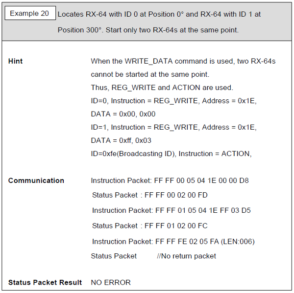
Action
This instruction is to execute the registered Reg Write instruction. The Action instruction is useful when multiple DYNAMIXEL’s are required to start moving at the same time. When several devices are controlled via communication, there is a minor time difference between enabling the first and last device. DYNAMIXEL has resolved this problem by using Action instruction.
| LEN | INST | P |
|---|---|---|
| 0x02 | 0x05 | - |
Example
Conditions
- All DYNAMIXEL’s have received Reg Write instructions.
- As the Packet ID is Broadcast ID (0xFE), the Status Packet is not return.
Action Instruction Packet
| H1 | H2 | Packet ID | LEN | INST | CKSM |
|---|---|---|---|---|---|
| 0xFF | 0xFF | 0xFE | 0x02 | 0x05 | 0xFA |
NOTE : Status Packet will not be returned if Broadcast ID(0xFE) is used.
Factory Reset
This instruction is to reset the Control Table of DYNAMIXEL to the factory default values.
WARNING :
- Make sure that the Factory Reset Instruction will reset the values in the EEPROM that you set previously.
- Broadcast ID(0xFE) cannot be used for Factory Reset instruction.
| LEN | INST | P |
|---|---|---|
| 0x02 | 0x06 | - |
Example
Conditions
- ID 0(RX-64) : Factory Reset DYNAMIXEL
Factory Reset Instruction Packet
| H1 | H2 | Packet ID | LEN | INST | CKSM |
|---|---|---|---|---|---|
| 0xFF | 0xFF | 0x00 | 0x02 | 0x06 | 0xF7 |
ID 0 Status Packet
| H1 | H2 | Packet ID | LEN | ERR | CKSM |
|---|---|---|---|---|---|
| 0xFF | 0xFF | 0x00 | 0x02 | 0x00 | 0xFD |
Reboot
This instruction restarts DYNAMIXEL.
- Supported products : DYNAMIXEL MX-12W(V41), MX-28/64/106(V40), MX(2.0) and X Series (excluding XL-320)
Example
Conditions
- ID 1(XM430-W210) : Reboot ID 1 DYNAMIXEL
Reboot Instruction Packet
| H1 | H2 | Packet ID | LEN | INST | CKSM |
|---|---|---|---|---|---|
| 0xFF | 0xFF | 0x01 | 0x02 | 0x08 | 0xF4 |
ID 1 Status Packet
| H1 | H2 | Packet ID | LEN | ERR | CKSM |
|---|---|---|---|---|---|
| 0xFF | 0xFF | 0x01 | 0x02 | 0x00 | 0xFC |
Sync Write
This instruction is used to control multiple DYNAMIXEL’s simultaneously with a single Instruction Packet transmission. When this instruction is used, several instructions can be transmitted at once, so that the communication time is reduced when multiple DYNAMIXEL’s are connected in a single channel. However, the Sync Write Instruction can only be used to a single address with an identical length of data over connected DYNAMIXEL’s. ID should be transmitted as Broadcast ID.
| Item | Description |
|---|---|
| Instruction | 0x83 |
| Length | ((L + 1) * N) + 4, L:Data Length, N:Number of DYNAMIXEL |
| Parameter 1 | Starting Address |
| Parameter 2 | Length of Data to write |
| Parameter 3 | [1st Device] ID |
| Parameter 4 | [1st Device] 1st Byte |
| Parameter 5 | [1st Device] 2nd Byte |
| … | … |
| Parameter L+3 | [1st Device] L-th Byte |
| Parameter L+4 | [2nd Device] ID |
| Parameter L+5 | [2nd Device] 1st Byte |
| Parameter L+6 | [2nd Device] 2nd Byte |
| … | … |
| Parameter 2L+4 | [2nd Device] L-th Byte |
Example
Conditions
- ID 0(MX-64) : Write 0x010 to Goal Position(30, 0x1E) and write 0x150 to Moving Speed(32, 0x20)
- ID 1(MX-64) : Write 0x220 to Goal Position(30, 0x1E) and write 0x360 to Moving Speed(32, 0x20)
Sync Write Instruction Packet
| H1 | H2 | Packet ID | LEN | INST | P1 | P2 | P3 | P4 | P5 | P6 | P7 | P8 | P9 | P10 | P11 | P12 | CKSM |
|---|---|---|---|---|---|---|---|---|---|---|---|---|---|---|---|---|---|
| 0xFF | 0xFF | 0xFE | 0x0E | 0x83 | 0x1E | 0x04 | 0x00 | 0x10 | 0x00 | 0x50 | 0x01 | 0x01 | 0x20 | 0x02 | 0x60 | 0x03 | 0x67 |
WARNING : Status Packet will not be returned if Broadcast ID(0xFE) is used.
Bulk Read
This instruction is used for reading values of multiple MX series DYNAMIXEL’s simultaneously by sending a single Instruction Packet. The packet length is shortened compared to sending multiple READ commands, and the idle time between the status packets being returned is also shortened to save communication time. However, this cannot be used to read a single module. If an identical ID is designated multiple times, only the first designated parameter will be processed.
- Supported products : DYNAMIXEL MX, MX(2.0) and X Series (excluding XL-320)
| Item | Description |
|---|---|
| Instruction | 0x92 |
| Length | 3N + 3 |
| Parameter 1 | 0x00 |
| Parameter 2 | [1st Device] Length of Data |
| Parameter 3 | [1st Device] ID |
| Parameter 4 | [1st Device] Starting address |
| … | … |
| Parameter 3N+2 | [Nth Device] Length of Data |
| Parameter 3N+3 | [Nth Device] ID |
| Parameter 3N+4 | [Nth Device] Starting address |
WARNING: Note that a parameter field construction of Bulk Read in DYNAMIXEL Protocol 2.0 differs from the parameter field construction of the Bulk Read in Protocol 1.0.
Example
Conditions
- ID 1(RX-64) : Read the 2-byte Goal Position value(30, 0x1E).
- ID 2(RX-64) : Read the 2-byte Present Position value(36, 0x24).
Bulk Read Instruction Packet
| H1 | H2 | Packet ID | LEN | INST | P1 | P2 | P3 | P4 | P5 | P6 | P7 | CKSM |
|---|---|---|---|---|---|---|---|---|---|---|---|---|
| 0xFF | 0xFF | 0xFE | 0x09 | 0x92 | 0x00 | 0x02 | 0x01 | 0x1E | 0x02 | 0x02 | 0x24 | 0x1D |
When Bulk Read instruction is received, DYNAMIXEL with ID 2 monitors the status packet being sent from ID 1 of the data bus (the preceeding device ID), and when device ID 1’s status packet transmission is completed, ID 2 sends its own status packet.
ID 1 Status Packet
| H1 | H2 | Packet ID | LEN | ERR | P1 | P2 | CKSM |
|---|---|---|---|---|---|---|---|
| 0xFF | 0xFF | 0x01 | 0x04 | 0x00 | 0x00 | 0x80 | 0x7A |
ID 2 Status Packet
| H1 | H2 | Packet ID | LEN | ERR | P1 | P2 | CKSM |
|---|---|---|---|---|---|---|---|
| 0xFF | 0xFF | 0x02 | 0x04 | 0x00 | 0x00 | 0x80 | 0x79 |
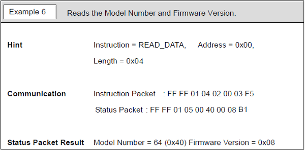
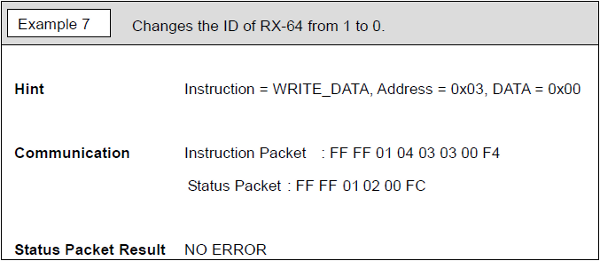
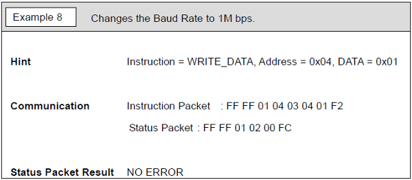
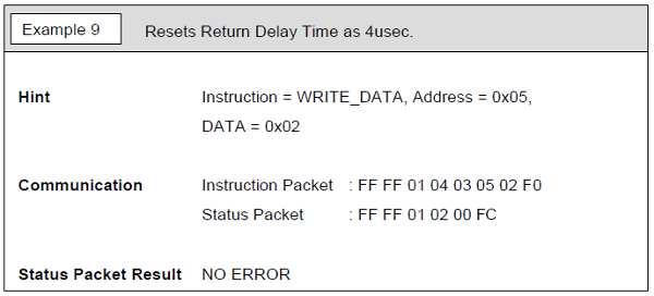
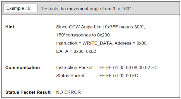
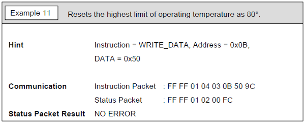
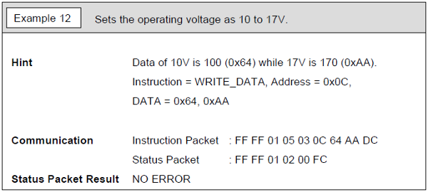
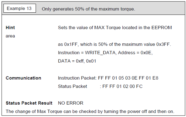
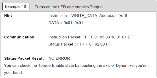
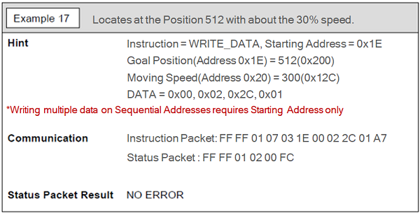
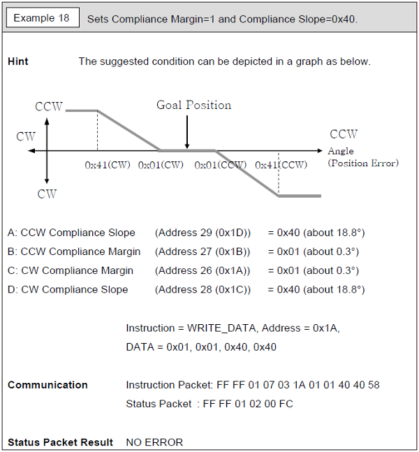
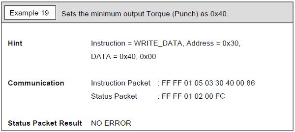
More Packet Examples