
Introduction
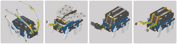
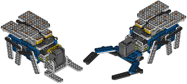
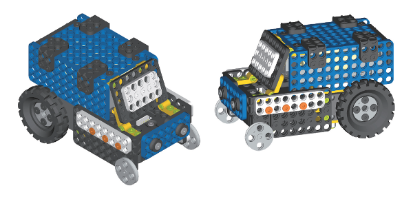
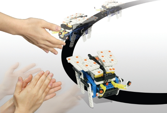
OLLO Bug Kit is the third kit among the kits for everyone, and the bug robots that play line-tracing game (The robots detect lines by themselves) and control game (The robots are controlled by wireless controllers) can be built by the kit. The assembly manual is included to build 4 types of bug robots: Beetles, Ladybugs, Callipogon Relictus, and Grasshoppers. Build the one and only robot for yourself.
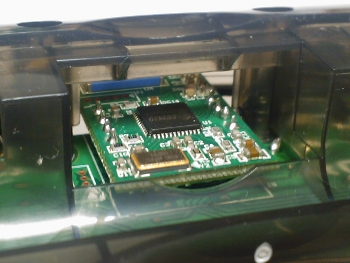
NOTE : All-in-one sensor type controller(CM-100) and Geared Motor are included in OLLO Bug Kit.
USB Downloader(LN-101) must be purchased to build and download the program that the users can control the bug robots directly.
Please refer to Programming on how to program.
The Examples of 4-Types of Bug Robot built according to the Assembly Manual.
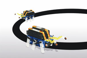
The Examples of Game with OLLO Bug Robots
OLLO Bug Game 1 Bug Battle
- Place a robot in the circle.
- Start the game with the whistling of the referee.
- Push the opponent’s robot to the outside of the circle, You Win~!!
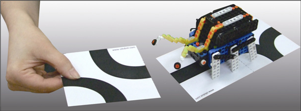
OLLO Bug Game 2 Bug Line-Tracing
- Place a bug robot on the line.
- The robot traces the line as soon as the power is turned on.
- Line-printed handout for OLLO Bug Line-Tracing : OLLO_LineTrace.pdf
Make the line to be traced by the bug using the enclosed puzzle board with various shapes. The robot can go anywhere it wants. Line-printed handout for bug puzzle race : OLLO_PuzzleRacing.zip
Getting Started
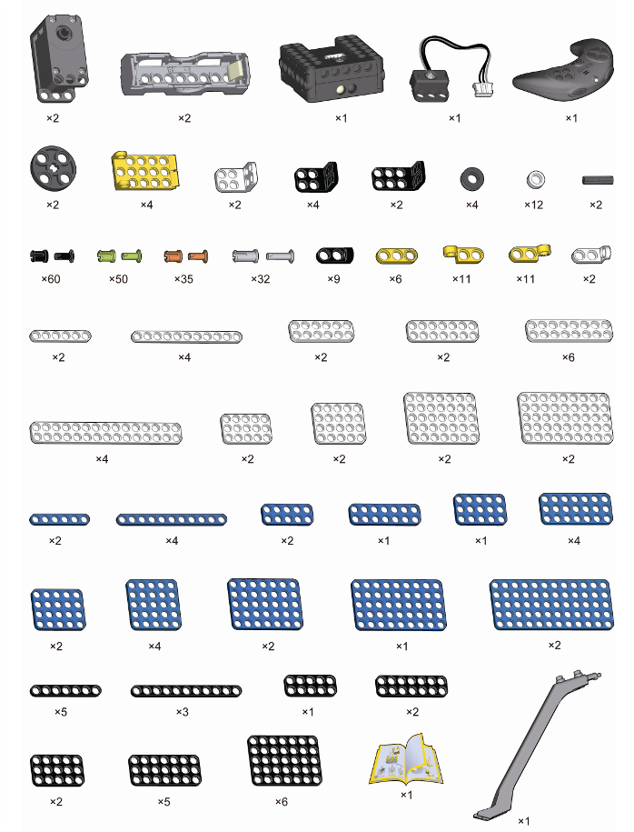
Part List
How to Play
The Basic Bug Program is supposed to be included when OLLO Bug Kit is manufactured. How to play of the basic bug program is as below.
Powering Bug
If you press the start button one time, the power is turned on; if you press the button once again, it is turned off. The bug controller (CM-100) has power-saving function, if the start button is not pressed again, the power is automatically turned off in 5 minutes. The power-saving function can be controlled by task code, and it is set to 5 minutes in the basic program.(See How to Control with Task Code)
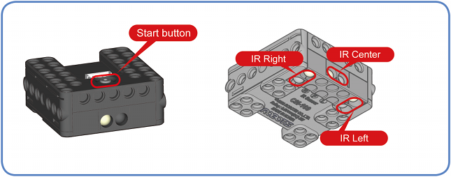
The Control Mode of the Remote Controller
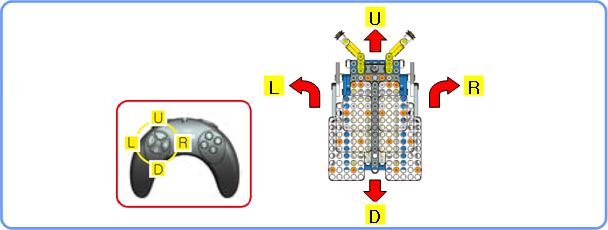
It is executed if the start button is pressed 1 or 2 times.( time: IR Channel 1, 2 times: IR Channel 2) The IR channel of RC-100 remote control must be matched to control wireleslly. (See How to Change the RC-100 IR Channel) The moving direction of the bug robot is controlled using U / L / D / R button of RC-100. If servo motor is connected to Port 3, the motor is controlled using button 1 and 3. If servo motor is connected to Port 4, the motor is controlled using button 2 and 4. (Servo motor is not a basic-offered item; please purchase and connect it.)
Line-Tracer Mode
If you press the start button 3 times, it is executed. The robot traces the black line on the white floor. If an object is detected, it stops; if you clap, it traces the line again.
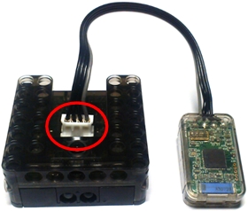
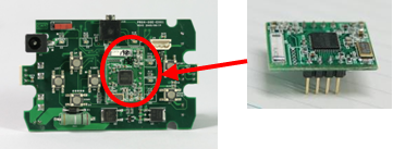
ZIGBee Wireless Control
ZIGBee
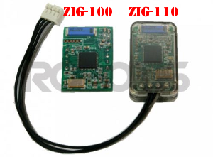
ZIG-100/110 uses ZIGBee for wireless communication. ZIGBee, like Bluetooth, is the communication technology commonly used in Personal Area Network (PAN). The communication quality of ZIGBee is better than that of IR, so it allows many users to control their robots without interferences.
CAUTION : Please note that not all products include a zigbee module and may need to be purchased separately.
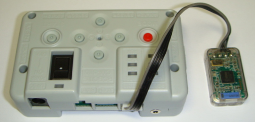
Controller & ZIGBee
OLLO and Bioloid both use the RC-100, which uses IR communication method. To upgrade to the Zigbee communication method, you must purchase the ZIG-110 set separately. The ZIG-110 set includes one Zig-100 module, which is attached to the RC-100, and one Zig-110 module which is attached to the Controller.
NOTE : The modules in a single Zigbee set have been preconfigured to communicate with each other. Therefore, a module from one set may not work with a module from another set. Please be careful not to mix them up.
| ZIG-100 installed in RC-100 | ZIG-110 installed in CM-100 |
|---|---|
 |
 |
| ZIG-110 installed in CM-510 | ZIG-100 installed in CM-5 |
|---|---|
 |
 |
Applications
Battle Bug
If you purchase and connect additional Servo Motor to OLLO Bug Kit, various types of battle bugs can be built. The Basic Program for OLLO Bug is programmed to be able to control using RC-100 when a servo motor is connected to port 3 or 4. If servo motor is connected to Port 3, the motor is controlled using button 1 and 3. If servo motor is connected to Port 4, the motor is controlled using button 2 and 4.
Car
If you purchase Big Tire Set additionally for OLLO Bug Kit, you can build cars with the tires.
Other Devices
Besides the parts introduced in ‘Building Battle Bugs’ and ‘Building Cars,’ the following parts for OLLO controller (CM-100) are used to build various types of robots.
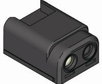
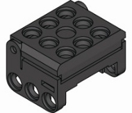
| IR Sensor | Touch Sensor | LED Module |
|---|---|---|
 |
 |
 |
Learning Program
Print on the Screen
Objective
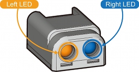
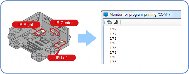
Write a program which prints out and checks the value of central IR sensor of the controller (CM-100) on the monitor for program output window.
Preparation
To accomplish the learning objectives, write a task code first; RoboPlus software which can pop up the monitor window for program printout and the controller(CM-100) which can transmit the value of central IR sensor to PC by executing task code are necessary. Moreover, USB Downloader(LN-101) is needed to connect PC and the controller.
Writing Task Code
-
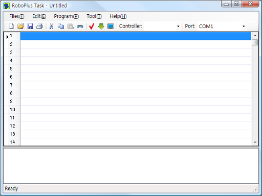
Execute RoboPlus Task Program.
-
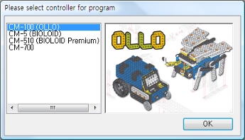
Select the Controller. If you select an empty line, and then Double Click or press Enter, Selecting Controller window is popped up. Select a controller, and then press OK button.
-
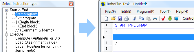
Writing Start Program. In the Select Instruction Type window, Select Program Start by Double clicking, and then press Enter.
-
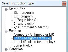
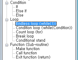
Enter Endless Loop. Use Endless Loop to read the IR sensor value repeatedly and print out on the screen. Select the empty line between { and } and Instruction Selection window pops up if you press Enter or Double click. Select Loop -> Endless Loop (while(1)).
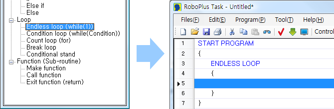
-
Enter Load. Use Load to read the IR sensor value and enter as Screen Display. Input in the empty line between { and } of Endless Loop by selecting Execute -> Load (Assignment Value).
-
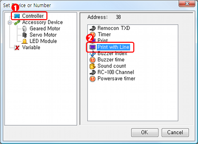
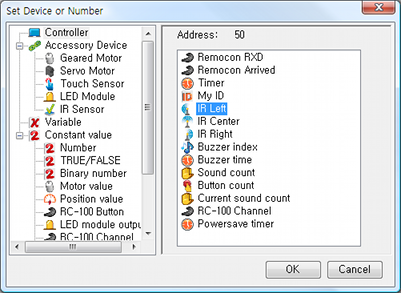
Load the value of Central IR Sensor by Screen Output. Select the left parameter( ? ) among the parameters of Load instruction. (Explanation Regrading Parameter). Parameter selection window is popped up as below if you double click ? and then press Enter. Select Controller -> Print with Line and press OK.
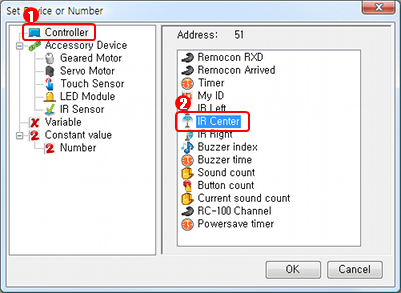
As above, input Controller -> Central IR Sensor in the right parameter ( ? ).
The following screen shows that all the parameters of Load instruction are entered.
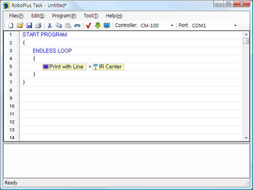
-
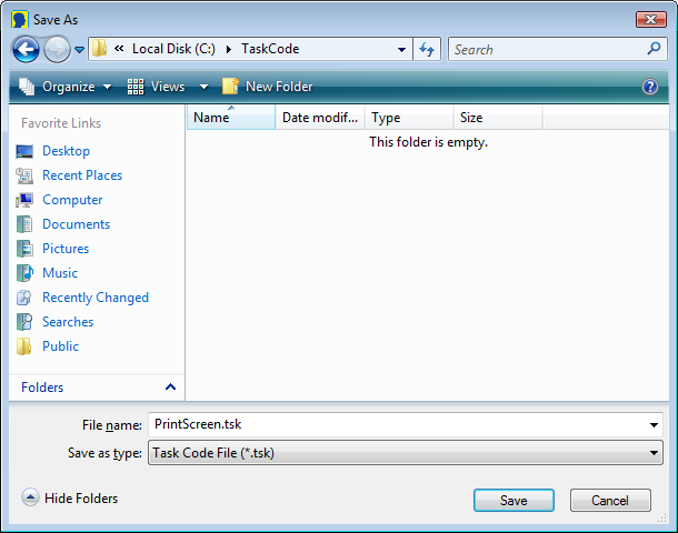
Save Task Code. Press Ctrl + S or Save Button to save.
Download Task Code
Download the task code written above to the controller. (How to Download Task code)
Run Program
-
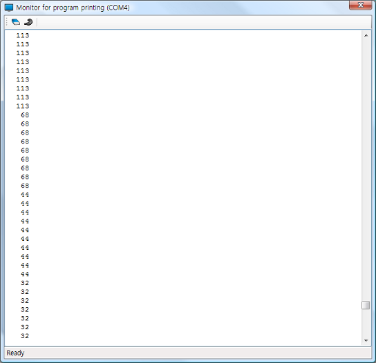
Popping up the monitor for program printing window. To see the screen output during the program execution, monitor for program printing window must be popped up before program execution. How to pop up the monitor for program printing window: Click View Program Output button in the Program Download window, click View Program Output button in Toolbox, select View Program Output(V) of Program(V) menu, or Press F5 button.
-
Executing the Program. Once the monitor for program printing window is popped up, execute the downloaded program for the controller. The internal LED is turned on by pressing the start button on the controller, and the downloaded program is executed. Check if the number values on the monitor for program printing window are changing or not by moving hands close and far from the front of central IR sensor of the controller.
Move the Bug
Objective
Let us move the bug forward, left, right, and backward. (The bug robot can be made with OLLO Explorer and Inventor.)
 |
 |
 |
 |
|---|---|---|---|
| Forward | Left | Right | Backward |
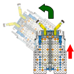
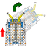
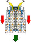
| Left Motor: Forward Right Motor: Forward |
Left Motor: Stop Right Motor: Forward |
Left Motor: Forward Right Motor: Stop |
Left Motor: Backward Right Motor: Backward |
Preparation
PC(RoboPlus Task Program), Assembled Bug Robot, USB Downloader(LN-101)
Writing Task Code
Move Forward
-
Executing RoboPlus Task and Creating program start (Please refer to See Printing Out the Screen). If RoboPlus Task is executed, the following screen can be seen.

-
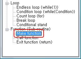
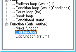
Making Forward Function (Please refer here for more information on functions). Functions must be made outside of { and } in program start. Therefore, let us start making the functions from the 6th line. First of all, select Make Function on Function (Sub-routine) in the select instruction window which pops up if the 6th line is selected.
The function is made as below.
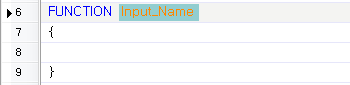
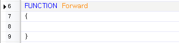
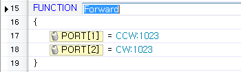
To designate function name, double click “Input_Name” part or enter the function name as “Forward” by pressing Enter as selected, and then press Enter again.
-
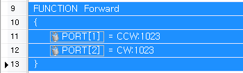
Motor Controlling to move the bug forward. For bug, two geared motors are supposed to move the legs made of left and right joints. To move the bug forward, both motors which move the legs must spin forward. To control geared motor, the motor control value must be entered using Load instruction. Select instruction type window is popped up if you double click the empty line between { and } of Forward function. Select Execute -> Load (Assignment value).
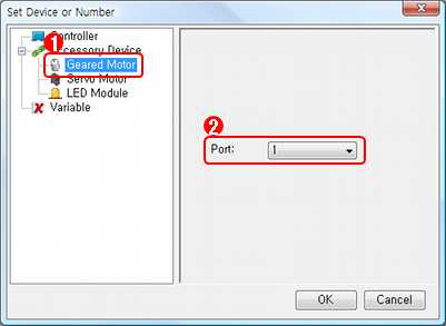
To control the geared motor (left motor) which is connected to port 1, select the first ? and enter Geared Motor Port 1.
To designate the speed and the spin direction of the left motor, select the second ? and enter Direction : CCW and power : 1023. (CCW represents counter clockwise and the direction of the left motor. Power 1023 is the maximum power value of geared motor; if the power is strong, the spinning power is also strong, The speed is fast.)
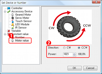
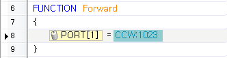
The following image shows the control value CCW:1023 is entered port 1 of the geared motor.
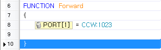
To control port 2 of the geared motor, insert an empty line under the instruction line just entered. To insert an empty line, press Space at the desired location. The following image shows the Space is pressed after clicking the } location of Forward.
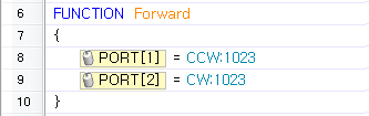
As the method above, insert an instruction line which orders to spin at the power of 1023 (Maximum power) and CW direction (Clockwise) to port 2 of the geared motor. (In case of the right motor, CW is the forward direction.)
-
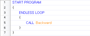
Calling Function (Please refer here for more information on functions). To execute Forward function as soon as the program of CM-100 is executed, Forward function must be called in Program Start. To make the program execute continuously, Endless Loop is used. Enter Endless Loop between { and } of Program Start.
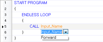
Call Forward function in Endless Loop sentences. Double click an empty line of Endless Loop or press Enter to select Call function on Function (Sub-routine).
Double click Input_Name part or press Enter to make the list of currently-made functions. Select Forward function or enter it directly.
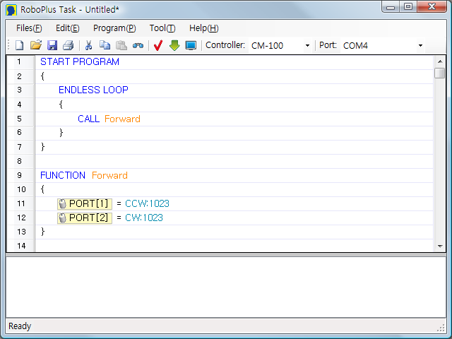
The following image shows the final results have been entered so far.
Moving Backward
For moving backward, simply change the direction of two motors from the forward direction. Thus, let us make Backward function by modifying the Forward function.
-
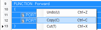
Copying the Forward function and then pasting (Pleaser refer to 5. Copy/Cut/Paste). Select all the Forward function while dragging the Mouse and pressing Shift Key or Ctrl Key.
In the menu popped up by right-click, Copy by selecting Copy(C) or pressing Ctrl + C.
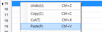
After clicking the 15th line under the Forward function, attach the function copied by clicking Paste(P) in the popped-up menu or pressing Ctrl + V.
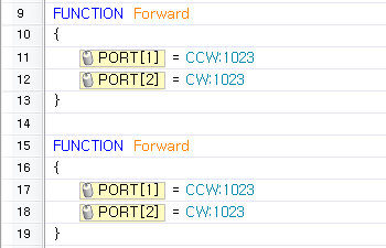
The following image shows the copy and the paste of Forward function are completed.
-
Changing the name into Backward function and the direction of the motors. Change the name of copied fuction from Forward to Backward. Double-click the function name part or press Enter to modify.
Change the spin direction of both motors to the opposite. Double-click the right parameter (CW:1023 or CCW:1023) part or Enter to modify.
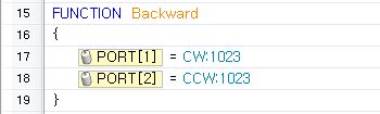
-
In start program, change the calling function from Forward to Backward. When the program is started, Backward function is executed repeatedly.
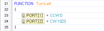
Turning Left
To make TurnLeft function, copy the Forward function the same as Backward function is copied and change the function name to TurnLeft; let the right motor (port 2) spin forward direction and stop only the left motor (port1) - Enter 0 in Power regardless CW/CCW; the bug robot turns left.
Turning Right
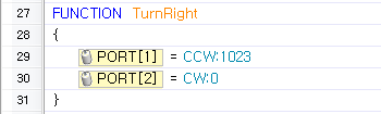
To make TurnRight function, copy the Forward function the same as the Backward function is copied and change the function name to TurnRight; let the left motor (port 1) spin forward direction and stop only the right motor (port 2) - Enter 0 in Power regardless CW/CCW; the bug robot turns right.
Download Task Code
Please refer to Program Download on the program download procedure.
Program Result File : bug_move.tsk
Run Program
If you turn on CM-100 by pressing the start button, the bug robot continuously moves forward or backward, or it turns left or right depending on the function called from Start Program.
Line Tracing Bug
Objective
The degree of IR reflection varies pursuant to the colors of objects. White reflects more IR, whereas black reflects less IR. Using such characteristics, let us program the IR sensor of CM-100 so that the robot can distinguish the white floor and the black line and trace the line. (It is programmed in the basis of Moving the Bug.)
Preparation
PC(RoboPlus Task Program), Assembled Bug Robot, USB Downloader(LN-101), a white board with a black line.
Writing Task Code
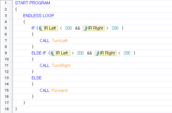
The algorithm of program which distinguishes the white floor and the black line and makes the bug trace the black line using left IR sensor and right IR sensor on the bottom of CM-100 is as below.
-
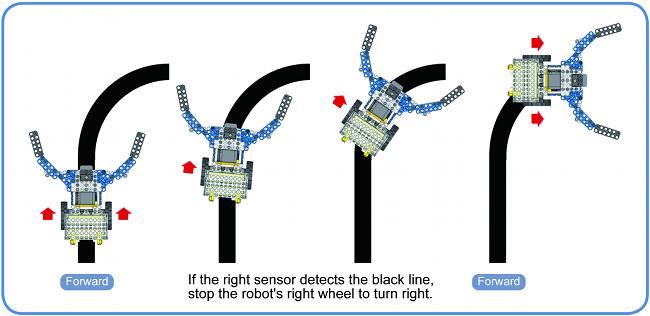
The right sensor detecting the black line (O), The left sensor detecting the black line (X) : Turn Right
If the black line is detected only by the right sensor, it means the line is curved to the right; change the robot’s moving direction to the right by stopping the right motor.
-
The right sensor detecting the black line (X), The left sensor detecting the black line (O) : Turn Left
In opposite to the case above, since the line is curved to the left, change the robot’s moving direction to the left by stopping the left motor.
-
The right sensor detecting the black line (X), The left sensor detecting the black line (X) : Forward
If both sensors do not detect the line, the robot moves forward without changing the direction since the line is located in between the sensors or the robot escaped from the line.
-
The right sensor detecting the black line (O), The left sensor detecting the black line (O) : Forward
If both sensors detect the line, the robot moves forward without changing the direction since there is a black line in width such as an intersection of crossroads(+) or the floor is black.
Enter the code which calls different function depending on the detecting conditions of the left/right IR sensors in program start, as mentioned In the previous example of Moving the Bug, and move the bug robot.
-
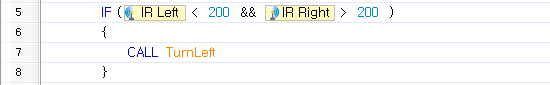
Turn left if the black line is detected only in the left IR sensor. Enter IF instruction of a conditional sentence to move in different ways depending on the conditions between { and } of Endless Loop in program. (Please refer here for more information on IF instruction). The screen after entering IF instruction is as below.
In the case that the black line is detected only on the left IR sensor, the value of left IR sensor is less than 200, while the value of right IR sensor is greater than 200. To find such conditions, enter left IR sensor in comparison parameter 1(the first ?) of the conditional sentence.
Since the left IR sensor value must be less than 200, < is entered as the comparison operator between the two comparison parameters.
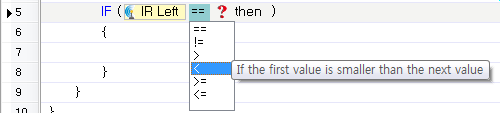
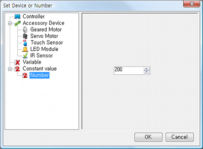
Enter 200 in the comparison parameter 2 (the second ?).
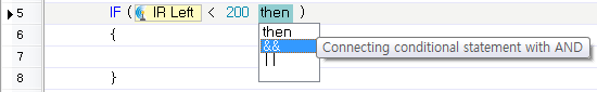
Since the conditions must be satisfied: ( Left IR Sensor < 100 ) and ( Right IR Sensor > 200 ), change the connecting operator to && (AND) by clicking then. If the connecting operator is changed, a conditional sentence is automatically added to the next.
Complete the IF instruction; enter right IR sensor on comparison parameter 1 of the second conditional sentence, > as the comparison operator, and 200 for comparison parameter 2.
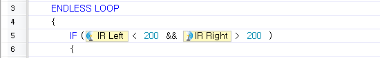
If the completed conditional sentence is True (If the black line is detected only on the left IR sensor), Calls TurnLeft function.
-
Conversely, turn right if the black line is detected only in the right IR sensor. To check the conditions continuously after the IF instruction of 1, enter ELSE IF instruction of a conditional sentence. If IF instruction conditional sentence of 1 is True, the ELSE IF instruction is not executed.
Not like in 1, if the black line is detected only by the right IR sensor, the left IR sensor value is greater than 200, while the right IR sensor value is less than 200. Regarding the conditional sentence, refer to 1 and write the comparison operator in the opposite of 1. In this case, TurnRight function is called.
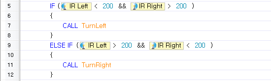
-
In the cases besides 1 and 2, that it, the black line is detected by both IR sensors, or the line is not detected by both IR sensors; the robot moves forward. In the case that not belongs to the conditional sentences mentioned above, enter ELSE instruction of a conditional sentence to move forward, and call Forward function.
Download Task Code
Please refer to Program Download on the program download procedure.
Program Result File : bug_linetracer.tsk
Download the Handout for Line Tracer
Run Program
Place the bug on the white board with a black line and play. Check if the bug traces the line or not.
Sensing Bug
Objective
Let us program a robot which traces the black line on the white floor like the line-tracing bug and stops if an object is detected by the central IR sensor; moreover, if clapping sounds are detected, it traces the black line again. (It is programmed in the basis of The Line-Tracing Bug)
Preparation
PC(RoboPlus Task Program), Assembled Bug Robot, USB Downloader(LN-101), a white board with a black line.
Writing Task Code
-
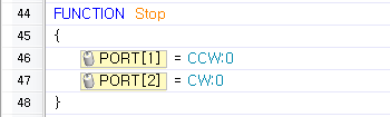
Add Stop Function. If an object is detected by the central IR sensor, Stop function is added to stop the movement. Make function referring to Moving the Bug.
Enter Power 0 in the Left and Right Geared Motors and make Stop function.
-
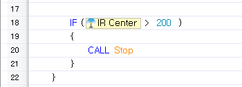
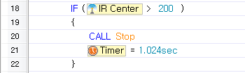
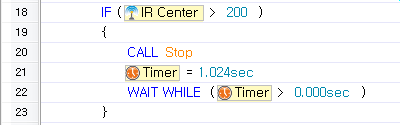
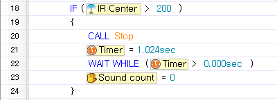
Call Stop function if an object is detected by the central IR sensor.
If the value of the central IR Sensor becomes greater than 200 by adding IF instruction in start program (an object is detected), call Stop function.
-
Wait shortly until the bug stops completely.
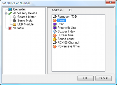
To use sound detection, the bug must stop completely; it is assumed that if the bug moves, the sounds of the bug are detected since the moving sounds such as the motor sound are recognized by the mic of CM-100 as quite loud sounds. Therefore, add the code which waits for certain time period using timer. (Please refer here for more information on timer.)
Enter 1 second in the timer using Load instruction.
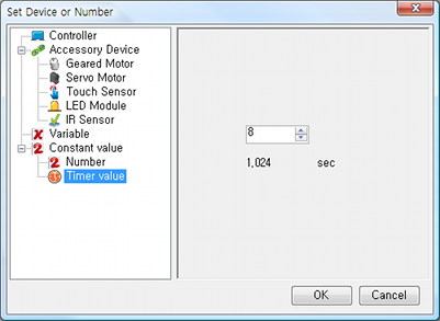
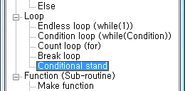
To wail until the timer becomes 0, use Conditional Stand instruction(Pleaser refer here for more information on conditional stand). It is Conditional Stand;; waits until the value becomes 0 by counting (while the value is greater than 0).
-
Wait until the clapping sounds come out through mic.
If the motions are stopped because an object is detected by the central IR sensor, make the code which waits until sounds are detected in stop status. Since Sound count is not automatically initialized to 0, it must be initialized to 0 by Load instruction before waiting(Please refer here for more information on sound count).
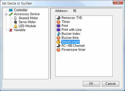
Wait if the Sound Count is 0.
Download Task Code
Please refer to Program Download on the program download procedure.
Program Result File : bug_sensor.tsk
Run Program
After executing the program, check if the bug robot stops or not when an object is detected by the central IR sensor. Later on, check if the bug moves again or not by clapping.
Control the Bug
Objective
Let us program a robot so as to control forward, backward, left and right using RC-100 controller(It is programmed in the basis of The sensor-responding bug).
Preparation
PC(RoboPlus Task Program), Assembled Bug Robot, USB Downloader(LN-101), RC-100
Writing Task Code
-
In the existing code, delete the surrounded part with { and } of Endless Loop in start program.
-
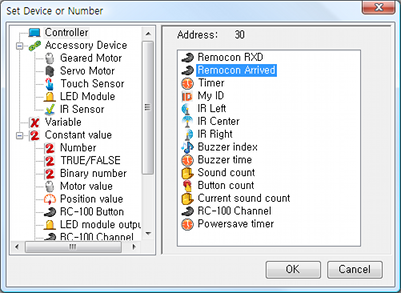
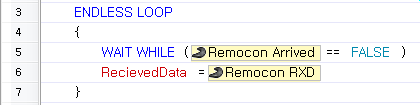
Wait until new wireless data arrive using Conditional Stand instruction to receive wireless control signal of RC-100(Please refer here for more information on new wireless data arrival).
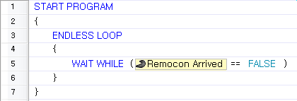
-
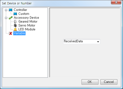
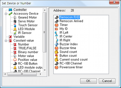
If the new wireless data is arrived, enter the received wireless data in ReceivedData variable using Load instruction(Please refer here for more information on Variable).
-
Separate the RC-100 Moving Control Button value from the Received Wireless Data values.
Enter U, L, D, R button values of RC-100 in MovingControlKey variable by separating necessary values through Bit Operator & from ReceivedData values using Compute instruction. Enter Compute instruction (Please refer here for more information on Compute instruction.)
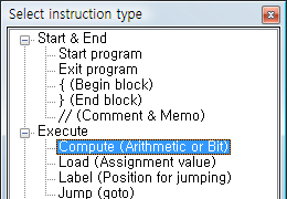
Enter MovingControlKey variable in Result column and then ReceivedData variable in Operation Parameter 1; select & (AND) as the next operator.
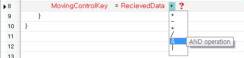
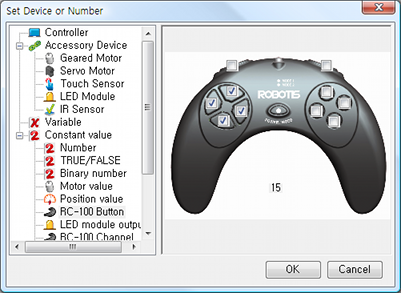
Select U, L, D, R as RC-100 button values and enter them in Operation Parameter 2(Please refer here for more information on RC-100 button values).
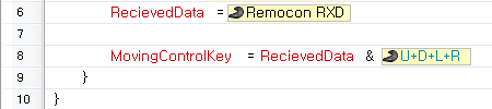
The following image shows the data are completely entered.
-
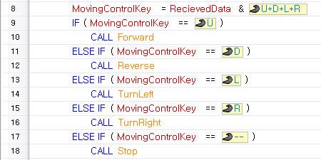
Move forward and backward and turn left and right depending on the value of MovingControlKey. it stops if all the MovingControlKey buttons are released.
Download Task Code
Please refer to Program Download on the program download procedure.
Program Result File : bug_rc.tsk
Run Program
After executing the program, control the robot forward, backward, left, and right using RC-100 controller.
[Download]
Download Task Code OLLO_BUG_Product_EN.tsk
NOTE : How to Download Task code
NOTE : How to play Bug