
Introduction
The Embedded C SDK enables users to create their own CM-530 firmware from scratch. Example implementations for basic features are provided on this page.
NOTE : This Embedded C SDK is intended for experienced users and programmers. ROBOTIS recommends that first time DYNAMIXEL users use the provided CM-530 firmware.
NOTE : Custom CM-530 firmware cannot be used with R+ Task software. After flashing custom firmware to the CM-530 it will not be usable with R+ Task until the default firmware is restored.
CM-530
The CM-530 SDK can be found on our Download Center
File Structure
- .. : stm32f10x_conf.h, Makefile, stm32.ld contants of these files and sub-directories.
- ../stm32f10x_lib : library files.
- ../APP/inc : example header files.
- ../APP/src : example source files.
Getting Started
WARNING: You may encounter following errors during installation:
- EX error :/usr/bin/sh: fork: Resource temporarily unavailable
- make: *** [CM530.lss] Error 128
Solution to the installtion errors:
- Download a file - msys-1.0-vista64.zip
- Extract the file.
- Copy and paste the extracted file into C:\WinARM\utils\bin.
Install JRE
JRE(Java Runtime Environment) is a required component to run Eclipse.
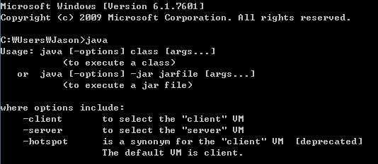
To verify whether JRE has been installed input ‘java’ at the command prompt. You can download JRE here.
Download JRE
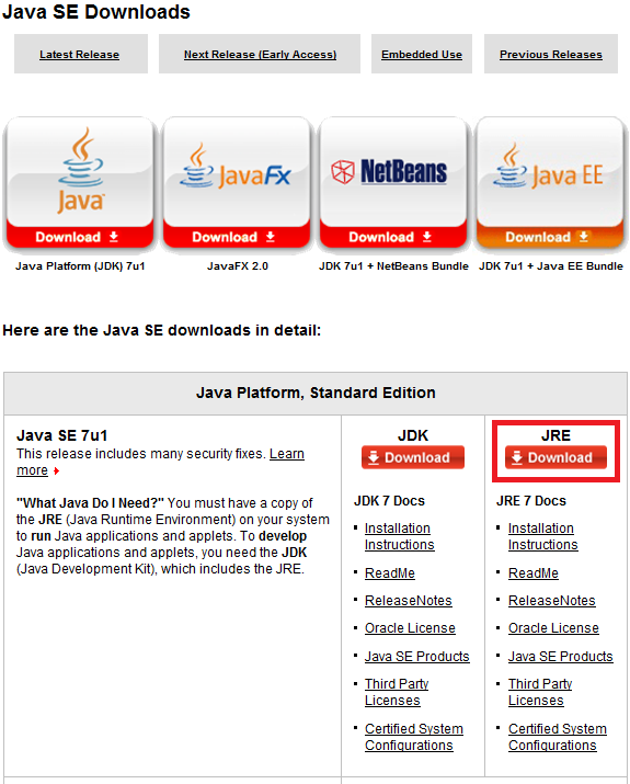
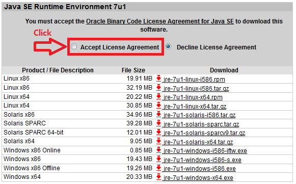
Select the version that best matches your working system.
Install WinARM
You can download WinARM
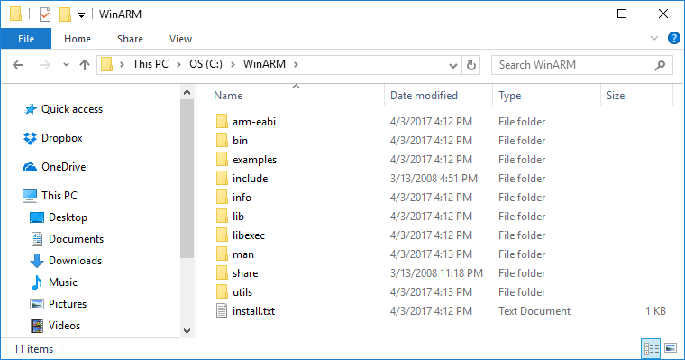
Download WinARM.
The downloaded file is a compressed file. Decompressed the file in C:\WinARM directory.
You must register WinARM to complete installation.
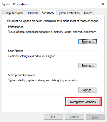
Go to [Control Panel] > [System] > [Advanced system settings] and select [Advanced] tab. Click on the [Environment Variables] button.
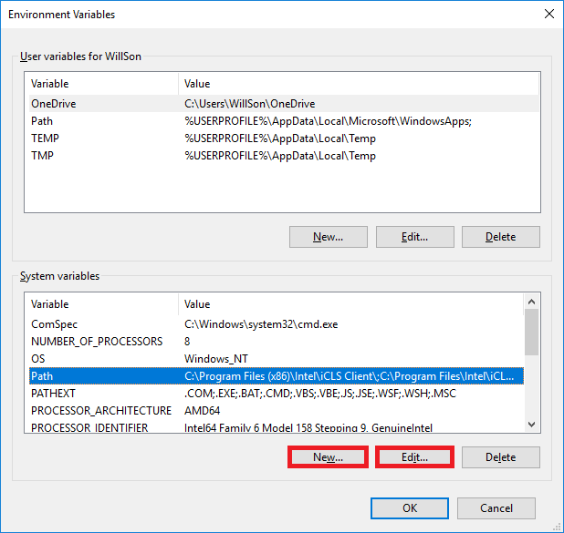
Find “Path” variable in the [System variables] group and edit its value.
If the “Path” variable is not exist then create new path by clicking on the “New” button.
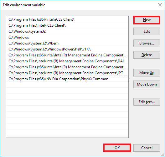
Click on the [New] button and add below items at the end of path lists for Windows 10 users.
C:\WinArm\bin
C:\WinARM\utils\bin
Other than Windows 10, append below items at the end of the variable value. Don’t miss the delimiter ‘;’(semicolon) in between each path.
C:\WinArm\bin;C:\WinARM\utils\bin;
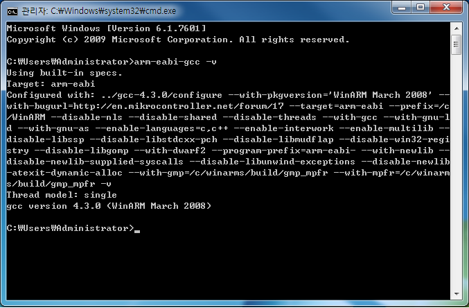
To verify proper installation, open the command window and type ‘arm-eabi-gcc –v’.
If it does not work well, turn off the cmd window and re-run cmd, then try again.
Install Eclipse
You can download Eclipse here.
Download Eclipse Helios SR2
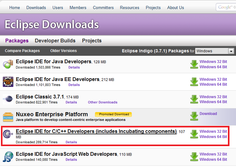
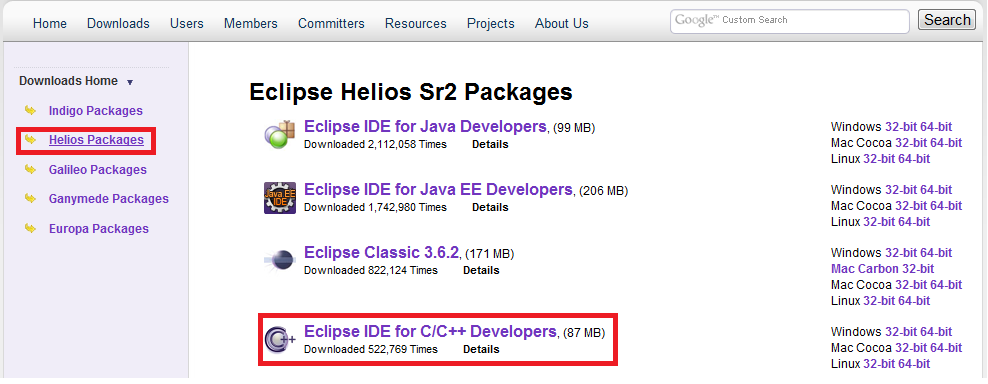
Select the version that best matches your working system.
To run Eclipse just run the eclipse.exe file.
Verify Installation
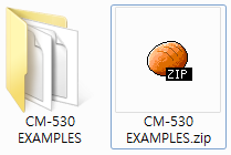
Verify successful installation.by opening a sample project.
Decompress the file (no root user rights needed).
When you first run Eclipse, it requires to set up workspace like the picture below.
- if you leave the default path, it may not be able to read the project. Please change it to another path.
Click on the left lower box to prevent this window.
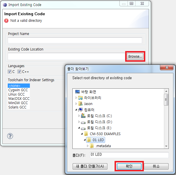
Run Eclipse and go to File – New – Makefile Project with Existing Code.

Click on Browse select 01 LED and click on Verify.

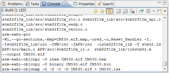
After selecting the project go to Project – Clean, Build

To see progress check the terminal window.
If progress is not as shown below then check the working development environment.
WARNING: You may encounter following errors during installation:
- EX error :/usr/bin/sh: fork: Resource temporarily unavailable
- make: *** [CM530.lss] Error 128
Solution to the installtion errors:
- Download a file - msys-1.0-vista64.zip
- Extract the file.
- Copy and paste the extracted file into C:\WinARM\utils\bin.
Restore RoboPlus
The result made by Embedded C is a controller firmware (bin file). If you install it, you cannot use RoboPlus since the existing controller firmware is erased. If you want to use RoboPlus again, you must install the original controller firmware built-in from the factory. You can install the original controller firmware easily using RoboPlus Manager.
For more information, please refer to Firmware Restoration of RoboPlus Manager.
Programming
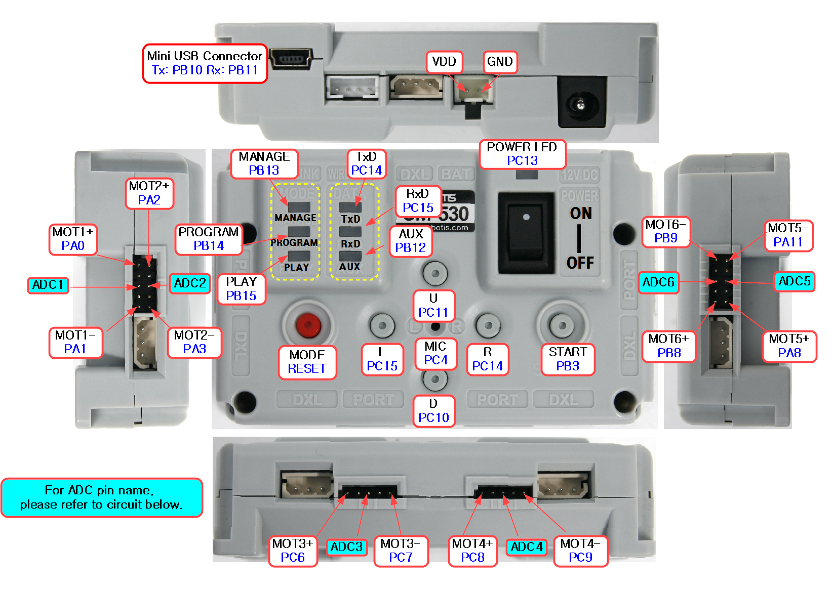
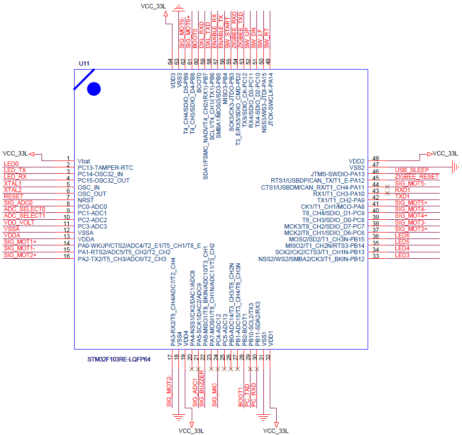
Hardware Port Map
The following hardware port map shows the hardware main pin functions of the controller.
Macros and libraries for the STM32F10X ports and internal functionalities are provided for easy access and control.
CM-530
| Pin # | Pin Name | NET NAME | Description |
|---|---|---|---|
| 1 | Vbat | VCC_33L | 3.3V power supply |
| 2 | PC13 | LED0 | LED POWER |
| 3 | PC14 | LED_TX | LED TX |
| 4 | PC15 | LED_RX | LED RX |
| 5 | OSC_IN | XTAL1 | X-TAL INPUT |
| 6 | OSC_OUT | XTAL2 | X-TAL OUTPUT |
| 7 | NRST | RESET | RESET |
| 8 | PC0 | SIG_ADC0 | ADC0 INPUT |
| 9 | PC1 | ADC_SELECT0 | ANALOG MUX SELECT0 |
| 10 | PC2 | ADC_SELECT1 | ANALOG MUX SELECT1 |
| 11 | PC3 | VDD_VOLT | input voltage ADC |
| 12 | VSSA | VSSA | ADC reference voltage 3.3V |
| 13 | VDDA | VDDA | ADC reference voltage 0V |
| 14 | PA0 | SIG_MOT1+ | #1 external port OUPUT |
| 15 | PA1 | SIG_MOT1- | 1 external port OUPUT |
| 16 | A2 | SIG_MOT2+ | #2 external port OUPUT |
| 17 | PA3 | SIG_MOT2- | #2 external port OUPUT |
| 18 | VSS4 | GND | 0V reference voltage |
| 19 | VDD4 | VCC_33L | 3.3V reference voltage |
| 20 | PA4 | NC | RESERVED |
| 21 | PA5 | SIG_ADC1 | ADC1 INPUT |
| 22 | PA6 | SIG_BUZZER | Buzzer OUTPUT |
| 23 | PA7 | NC | RESERVED |
| 24 | PC4 | SIG_MIC | MIC Signal INPUT |
| 25 | PC5 | NC | RESERVED |
| 26 | PB0 | NC | RESERVED |
| 27 | PB1 | NC | RESERVED |
| 28 | PB2 | BOOT1 | RESERVED |
| 29 | PB10 | PC_TXD | PC transmit |
| 30 | PB11 | PC_RXD | PC receive |
| 31 | VSS1 | GND | 0V reference voltage |
| 32 | VDD1 | VCC_33L | 3.3V reference voltage |
| 33 | PB12 | LED3 | LED AUX |
| 34 | PB13 | LED4 | LED MANAGE |
| 35 | PB14 | LED5 | LED PROGRAM |
| 36 | PB15 | LED6 | LED PLAY |
| 37 | PC6 | SIG_MOT3+ | #3 external port OUPUT |
| 38 | PC7 | SIG_MOT3- | #3 external port OUPUT |
| 39 | PC8 | SIG_MOT4+ | #4 external port OUPUT |
| 40 | PC9 | SIG_MOT4- | #4 external port OUPUT |
| 41 | PA8 | SIG_MOT5+ | #5 external port OUPUT |
| 42 | PA9 | NC | RESERVED |
| 43 | PA10 | NC | RESERVED |
| 44 | PA11 | SIG_MOT5- | #5 external port OUPUT |
| 45 | PA12 | ZIGBEE_RESET | Zigbee ENABLE |
| 46 | PA13 | USB_SLEEP | USB connections |
| 47 | VSS2 | GND | 0V reference voltage |
| 48 | VDD2 | VCC_33L | 3.3V reference voltage |
| 49 | PA14 | SW_RT | R Button |
| 50 | PA15 | SW_LF | L Button |
| 51 | PC10 | SW_DN | D Button |
| 52 | PC11 | SW_UP | U Button |
| 53 | PC12 | ZIGBEE_TXD | Zigbee transmit |
| 54 | PD2 | ZIGBEE_RXD | Zigbee receive |
| 55 | PB3 | SW_START | START Button |
| 56 | PB4 | ENABLE_TX | Dynamixel transmit ENABLE |
| 57 | PB5 | ENABLE_RX | Dynamixel receive ENABLE |
| 58 | PB6 | DXL_TXD | Dynamixel transmit |
| 59 | PB7 | DXL_RXD | Dynamixel receive |
| 60 | BOOT0 | BOOT0 | RESERVED |
| 61 | PB8 | SIG_MOT6+ | #6 external port OUPUT |
| 62 | PB9 | SIG_MOT6- | #6 external port OUPUT |
| 63 | VSS3 | GND | 0V reference voltage |
| 64 | VDD3 | VCC_33L | 3.3V reference voltage |
The external ports of the CM-530 are listed below from 1 to 6. Please refer to CM-530 controller for reference regarding ports.
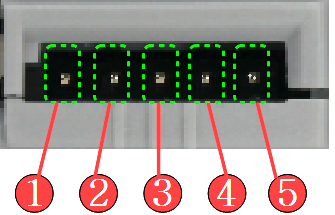
- OUT1 : Output voltage 3.3V (0.3A max)
- VCC (5V)
- ADC : Ports for analog signal devices
- GND
- OUT2 : Output voltage 3.3V (0.3A max)
Open Project
Open 01 LED project
Run Eclipse and go to Fle – New – makefile Project with existing code.

Click on Browse select 01 LED and click on Verify.
After selecting the project go to Project – Clean, Build
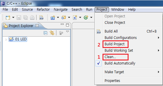
To see progress check the terminal window.
If progress is not as shown below then check the working development environment.

Download bin File
After a successful build the bin file will be located at the sample directory.
The firmware can be loaded into the controller via bootloader from RoboPlus Terminal.
Please refer to the bootloader program for firmware installation and running.
Boot Loader
Boot Loader makes the users possible to use the controller. Boot Loader cannot be erased by the users. If it is broken down, the controller cannot be used. Boot Loader is built-in on the controller when it is manufactured in the factory.
The available commands in Boot Loader can be found using “Help” command.
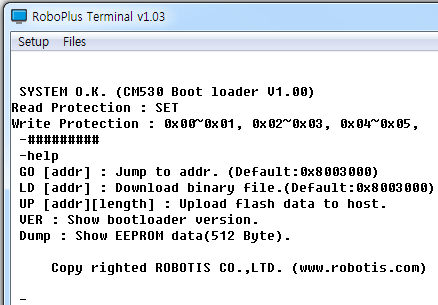
Entering/Exiting Boot Loader
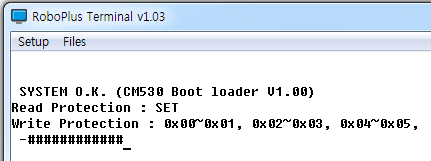
Entering Boot Loader
To enter into the boot loader, while pressing the ‘#’ button(Shift + 3), turn on the controller or press down the reset switch.
If you did correctly, following screen page will be shown.
Exiting Boot Loader
If the work is completed, you may exit by jumping to the desired address using “GO” command or by resetting the controller.
How to Use APP/SYS
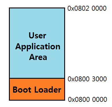
The program start position can be set by APP/SYS command. Once the program start position is set, the program is executed on the program start position when the power is turned on or reset.
The memory map using STM32F103RE is as below.
-
If you input APP command on the window after entering Boot Loader, User Application Area is executed first after the next reset.
(Most programs such as provided firmware, user program etc. start from 0 address, if there are no specific reasons.) -
If you input SYS command on the window after entering Boot Loader, Boot Loader is executed after the next reset.
(It is started as Boot Loader status, even if you do not press “#.”)
Install/Execute Program
Preparations for installing a firmware of the controller are as follows:
- Prepare a firmware (hex file) of the controller to be installed.
- Connect PC and the controller.
- Set the communication port by executing RoboPlus Terminal.
- Execute Boot Loader of the controller. (Please refer to how to enter Boot Loader.)
A firmware of the controller can be installed according to the procedure below.
-
Input “L” command (or Load) in Boot Loader.
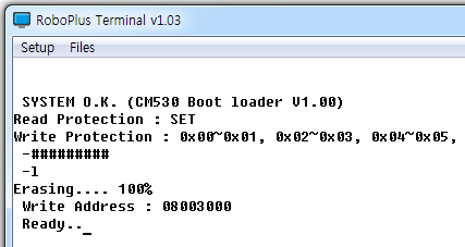
-
Select “Transmit File” in the Files menu of RoboPlus Terminal, and then select the prepared firmware. (bin file)
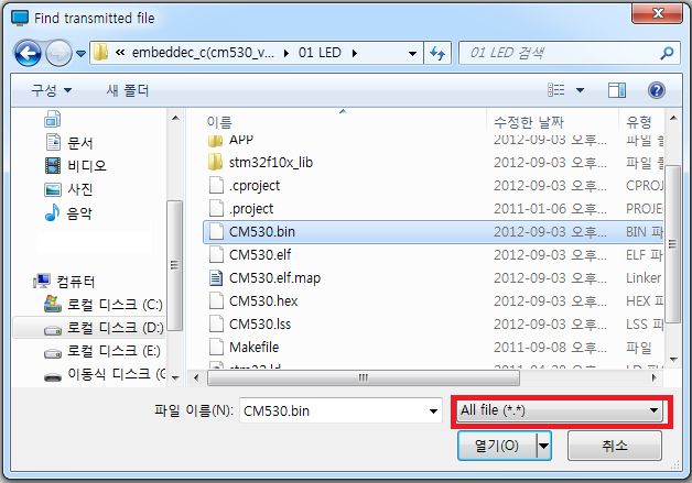
-
The file is transmitted. Please do not let the power of the controller turn off, and be careful the cable does not take off while the file is being transmitted.
-
When the file transmission is completed, you can execute the program using GO command.
- In case of inputting only “GO” command, the program is executed from 0 address.
- Like G [Address], if you input execution address (hexadecimal) after “G” command, the program is executed from the location.
Additional Description
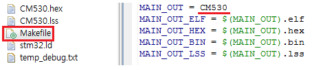
File creation
The newly made file can be changed from the sample\makefile designation. From makefile you can rename the file after ‘MAIN_OUT =’.
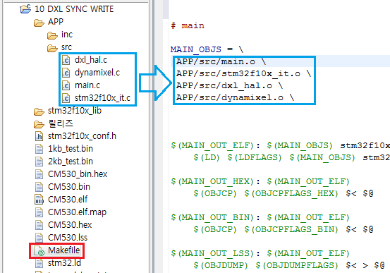
Object file list
From the illustration ‘sample\app\src’ directory object files are produced from the .c files; where the Makefile requires these object files.
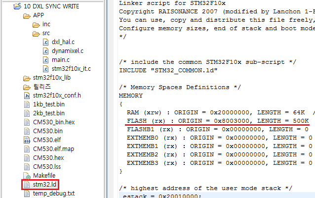
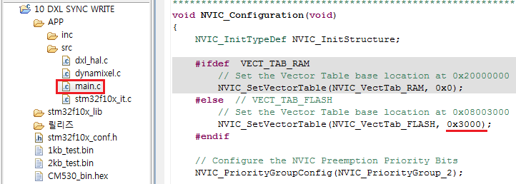
Firmware start address
The memory maps and bootloader domain are divided into the following.
The firmware starting address is 0X8003000 by default user-modifiable.
The following example is with address 0X8003000
-
changing stm32.ld
-
changing the vector table
Examples
LED Control
Each LED of the controller can be controlled.
- Prepare
- CM-530
- Theory
- The micro controller can control the peripheral devices such as LED connected to the controller through I/O Port. You can control LEDs on the controller using this example.
- Refer to controller’s port for port and pin number in 01 LED\app\src\main.c
-
Source
int main(void) { /* System Clocks Configuration */ RCC_Configuration(); /* NVIC configuration */ NVIC_Configuration(); /* Configure the GPIO ports */ GPIO_Configuration(); SysTick_Configuration(); while(1) { GPIO_SetBits(PORT_LED_POWER, PIN_LED_POWER); GPIO_ResetBits(PORT_LED_MANAGE, PIN_LED_MANAGE); mDelay(250); GPIO_SetBits(PORT_LED_MANAGE, PIN_LED_MANAGE); GPIO_ResetBits(PORT_LED_PROGRAM, PIN_LED_PROGRAM); mDelay(250); GPIO_SetBits(PORT_LED_PROGRAM, PIN_LED_PROGRAM); GPIO_ResetBits(PORT_LED_PLAY, PIN_LED_PLAY); mDelay(250); GPIO_SetBits(PORT_LED_PLAY, PIN_LED_PLAY); GPIO_ResetBits(PORT_LED_TX, PIN_LED_TX); mDelay(250); GPIO_SetBits(PORT_LED_TX, PIN_LED_TX); GPIO_ResetBits(PORT_LED_RX, PIN_LED_RX); mDelay(250); GPIO_SetBits(PORT_LED_RX, PIN_LED_RX); GPIO_ResetBits(PORT_LED_AUX, PIN_LED_AUX); mDelay(250); GPIO_SetBits(PORT_LED_AUX, PIN_LED_AUX); GPIO_ResetBits(PORT_LED_POWER, PIN_LED_POWER); mDelay(250); } return 0; } - Result
- All LEDs will be turned on in order.
Button
Input of the button can be received.
- Prepare
- CM-530
- Theory
- Electronic signals of the devices connected to the controller can be read through I/O Port of the micro controller. You can see the status of pressed built-in switches through this example.
- Refer to controller’s port for port and pin number in 02 BUTTON \app\src\main.c
-
Source
int main(void) { /* System Clocks Configuration */ RCC_Configuration(); /* NVIC configuration */ GPIO_Configuration(); /* Configure the GPIO ports */ NVIC_Configuration(); GPIO_ResetBits(PORT_LED_POWER, PIN_LED_POWER); while(1) { if( GPIO_ReadInputDataBit(PORT_SW_UP, PIN_SW_UP) != SET ) GPIO_ResetBits(PORT_LED_MANAGE, PIN_LED_MANAGE); else if( GPIO_ReadInputDataBit(PORT_SW_DOWN, PIN_SW_DOWN) != SET ) GPIO_ResetBits(PORT_LED_AUX, PIN_LED_AUX); else if( GPIO_ReadInputDataBit(PORT_SW_LEFT, PIN_SW_LEFT) != SET ) GPIO_ResetBits(PORT_LED_PROGRAM, PIN_LED_PROGRAM); else if( GPIO_ReadInputDataBit(PORT_SW_RIGHT, PIN_SW_RIGHT) != SET ) GPIO_ResetBits(PORT_LED_PLAY, PIN_LED_PLAY); else if( GPIO_ReadInputDataBit(PORT_SW_START, PIN_SW_START) != SET ) { GPIO_ResetBits(PORT_LED_MANAGE, PIN_LED_MANAGE); GPIO_ResetBits(PORT_LED_PROGRAM, PIN_LED_PROGRAM); GPIO_ResetBits(PORT_LED_PLAY, PIN_LED_PLAY); GPIO_ResetBits(PORT_LED_TX, PIN_LED_TX); GPIO_ResetBits(PORT_LED_RX, PIN_LED_RX); GPIO_ResetBits(PORT_LED_AUX, PIN_LED_AUX); } else { GPIO_SetBits(PORT_LED_MANAGE, PIN_LED_MANAGE); GPIO_SetBits(PORT_LED_PROGRAM, PIN_LED_PROGRAM); GPIO_SetBits(PORT_LED_PLAY, PIN_LED_PLAY); GPIO_SetBits(PORT_LED_TX, PIN_LED_TX); GPIO_SetBits(PORT_LED_RX, PIN_LED_RX); GPIO_SetBits(PORT_LED_AUX, PIN_LED_AUX); } } return 0; } - Result
- If you press buttons, depending on pressed buttons, different LEDs are turned on.
Serial Communication
PC and the controller can perform serial communication.
- Prepare
- CM-530 PC connection status
- The communication speed of the example is set to 57600bps.
- Theory
- Serial communication is the basic method to show the value of the controller to users by transmitting to PC. You can try serial communication with the controller through this example.
- The microcontroller and PC comm are in USART channel 3
- Refer to controller’s port for port and pin number in 03 SERIAL COMMUNICATION\APP\src\main.c
-
Source
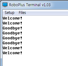
int main(void) { /* System Clocks Configuration */ RCC_Configuration(); /* NVIC configuration */ NVIC_Configuration(); /* Configure the GPIO ports */ GPIO_Configuration(); /* USART Configuration */ USART_Configuration(57600); GPIO_ResetBits(PORT_LED_POWER, PIN_LED_POWER); while(1) { ReceivedData = RxDByte_PC(); if(ReceivedData == 'w') TxDString("Welcome!\r\n"); else if(ReceivedData == 'g') TxDString("Goodbye!\r\n"); } return 0; } - Result
-
Press the w for welcome and g key for goodbye.
-
Buzzer
Buzzer on the controller can be used.
- Prepare
- CM-530
- Theory
- Signals of the buzzer circuit can be controlled through I/O Port of the micro controller. The buzzer can play different musical notes by adjusting signal frequency.
-
Refer to controller’s port for port and pin number in 04 BUZZER\APP\src\main.c
- The relationship between musical scale and frequency is as below.
-
Time is a reciprocal number of frequency. The conversion formula is as below.
Time(Sec) = 1 / (Frequency)
Octave
/Scale1 2 3 4 5 6 7 8 C 32.7032 65.4064 130.8128 261.6256 523.2511 1046.502 2093.005 4186.009 C# 34.6478 69.2957 138.5913 277.1826 554.3653 1108.731 2217.461 4434.922 D 36.7081 73.4162 146.8324 293.6648 587.3295 1174.659 2349.318 4698.636 D# 38.8909 77.7817 155.5635 311.1270 622.2540 1244.508 2489.016 4978.032 E 41.2034 82.4069 164.8138 329.6276 659.2551 1318.510 2637.020 5274.041 F 43.6535 87.3071 174.6141 349.2282 698.4565 1396.913 2793.826 5587.652 F# 46.2493 92.4986 184.9972 369.9944 739.9888 1479.978 2959.955 5919.911 G 48.9994 97.9989 195.9977 391.9954 783.9909 1567.982 3135.963 6271.927 G# 51.9130 103.8262 207.6523 415.3047 830.6094 1661.219 3322.438 6644.875 A 55.0000 110.0000 220.0000 440.0000 880.0000 1760.000 3520.000 7040.000 A# 58.2705 116.5409 233.0819 466.1638 932.3275 1864.655 3729.310 7458.620 G 61.7354 123.4708 246.9417 493.8833 987.7666 1975.533 3951.066 7902.133 Unit : Hz
-
Source
int main(void) { /* System Clocks Configuration */ RCC_Configuration(); /* NVIC configuration */ NVIC_Configuration(); /* Configure the GPIO ports */ GPIO_Configuration(); SysTick_Configuration(); GPIO_ResetBits(PORT_LED_POWER, PIN_LED_POWER); while(1) { if( GPIO_ReadInputDataBit(PORT_SW_UP, PIN_SW_UP) != SET ) { GPIO_ResetBits(PORT_LED_MANAGE, PIN_LED_MANAGE); GPIO_ResetBits(PORT_LED_PROGRAM, PIN_LED_PROGRAM); GPIO_ResetBits(PORT_LED_PLAY, PIN_LED_PLAY); GPIO_ResetBits(PORT_LED_TX, PIN_LED_TX); GPIO_ResetBits(PORT_LED_RX, PIN_LED_RX); GPIO_ResetBits(PORT_LED_AUX, PIN_LED_AUX); GPIO_ResetBits(PORT_BUZZER, PIN_BUZZER); mDelay(1); GPIO_SetBits(PORT_BUZZER, PIN_BUZZER); mDelay(1); } else { GPIO_SetBits(PORT_LED_MANAGE, PIN_LED_MANAGE); GPIO_SetBits(PORT_LED_PROGRAM, PIN_LED_PROGRAM); GPIO_SetBits(PORT_LED_PLAY, PIN_LED_PLAY); GPIO_SetBits(PORT_LED_TX, PIN_LED_TX); GPIO_SetBits(PORT_LED_RX, PIN_LED_RX); GPIO_SetBits(PORT_LED_AUX, PIN_LED_AUX); GPIO_SetBits(PORT_BUZZER, PIN_BUZZER); } } } - Result
- Press start the power LED turns on, 6 other LED’s turn on, and buzzer sounds off.
MIC
External sounds can be detected through MIC.
- Prepare
- CM-530
- Theory
- If more than a certain level of sounds is detected on the MIC circuit, signals are made to I/O Port of the micro controller. External sounds can be detected by sensing the signals.
- Refer to controller’s port for port and pin number in 05 MIC\APP\src\main.c
- Source
int main(void)
{
  /* System Clocks Configuration */
  RCC_Configuration();
  /* NVIC configuration */
  NVIC_Configuration();
  /* NVIC configuration */
  GPIO_Configuration();
  SysTick_Configuration();
  GPIO_ResetBits(PORT_LED_POWER, PIN_LED_POWER);

  while(1)
  {
    if( GPIO_ReadInputDataBit(PORT_MIC, PIN_MIC) != SET)
    {
      GPIO_ResetBits(PORT_LED_MANAGE, PIN_LED_MANAGE);
      GPIO_ResetBits(PORT_LED_PROGRAM, PIN_LED_PROGRAM);
      GPIO_ResetBits(PORT_LED_PLAY, PIN_LED_PLAY);
      GPIO_ResetBits(PORT_LED_TX, PIN_LED_TX);
      GPIO_ResetBits(PORT_LED_RX, PIN_LED_RX);
      GPIO_ResetBits(PORT_LED_AUX, PIN_LED_AUX);
      mDelay(1000);
    }
    else
    {
      GPIO_SetBits(PORT_LED_MANAGE, PIN_LED_MANAGE);
      GPIO_SetBits(PORT_LED_PROGRAM, PIN_LED_PROGRAM);
      GPIO_SetBits(PORT_LED_PLAY, PIN_LED_PLAY);
      GPIO_SetBits(PORT_LED_TX, PIN_LED_TX);
      GPIO_SetBits(PORT_LED_RX, PIN_LED_RX);
      GPIO_SetBits(PORT_LED_AUX, PIN_LED_AUX);
    }
  }
  return 0;
}
- Result
- When the MIC signals are detected, all LEDs are turned on and off for a second.
OLLO Servo CW/CCW
Learning ollo servo motor rotation direction
- Prepare
- CM-530
- OLLO servo motor (Connected to the external port No.1)
- Theory
-
The controller controls rotation direction with MOT1+ and MOT1- via SIG_MOT1+ and SIG_MOT1-
-
Refer to controller’s port for port and pin number in 06 OLLO MOTOR ROTATE\APP\src\main.c
- Source
int main(void)
{
   /* System Clocks Configuration */
  RCC_Configuration();
  /* NVIC configuration */
  NVIC_Configuration();
  /* GPIO configuration */
  GPIO_Configuration();
  SysTick_Configuration();
  GPIO_ResetBits(PORT_SIG_MOT1P,PIN_SIG_MOT1P);
  GPIO_ResetBits(PORT_SIG_MOT1M,PIN_SIG_MOT1M);
  GPIO_ResetBits(PORT_LED_POWER, PIN_LED_POWER);

  while(1)
  {
    GPIO_SetBits(PORT_SIG_MOT1P,PIN_SIG_MOT1P);
    GPIO_ResetBits(PORT_SIG_MOT1M,PIN_SIG_MOT1M);
    mDelay(5000);
    GPIO_SetBits(PORT_SIG_MOT1M,PIN_SIG_MOT1M);
    mDelay(5000);
    GPIO_SetBits(PORT_SIG_MOT1P,PIN_SIG_MOT1P);
    GPIO_SetBits(PORT_SIG_MOT1M,PIN_SIG_MOT1M);
    mDelay(2000);
  }
  return 0;
}
- Result
- The servo motor rotates for 5 seconds and repeats rotating after a 2-second halt.
OLLO Servo Position
Learning ollo servo motor position reading
- Prepare
- CM-530
- OLLO servo motor
- Theory
- The controller can change input analog signals into digital form. This example converts the motor’s analog position signal.
-
Refer to controller’s port for port and pin number in 06 OLLO MOTOR ROTATE\APP\src\main.c
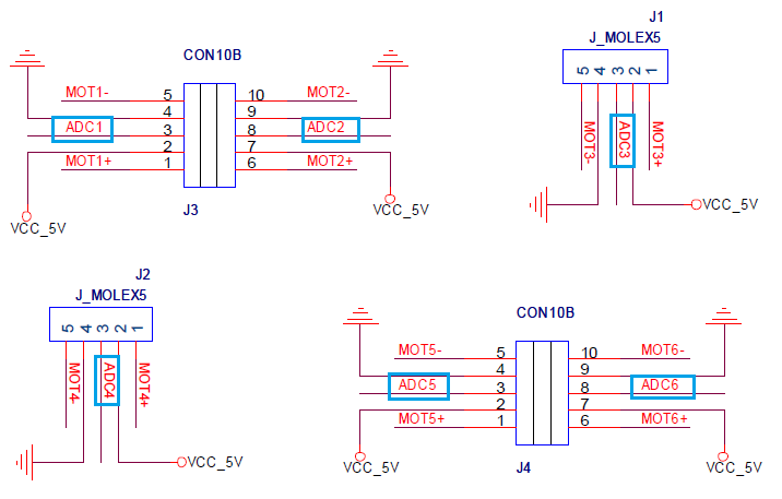

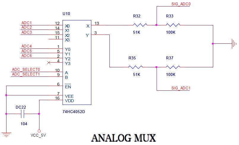
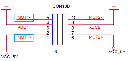
- The ANALOG MUX (74HC4052D) blocks impedance and converts voltage from 5V to 3.3V.
- ADX MUX circuit combines signal from ADC_SELECT0, and ADC_SELECT1; SIG_ADC0 selects a signal from ADC1, ADC2, or ADC3 and feeds it into the microcontroller; SIG_ADC1 selects a signal from ADC4, ADC5, or ADC6 and feeds it into the microcontroller; then this signal gets converted into digital.
- Refer to controller’s port for port and pin number in 07 OLLO MOTOR POSITION\APP\src\main.c
- Source
int main(void)
{
  /* System Clocks Configuration */
  RCC_Configuration();
  /* NVIC configuration */
  NVIC_Configuration();
  /* GPIO configuration */
  GPIO_Configuration();
  SysTick_Configuration();
  /* ADC configuration */
  ADC_Configuration();
  GPIO_ResetBits(PORT_SIG_MOT1P,PIN_SIG_MOT1P);
  GPIO_ResetBits(PORT_SIG_MOT1M,PIN_SIG_MOT1M);
  GPIO_ResetBits(PORT_SIG_MOT2P,PIN_SIG_MOT2P);
  GPIO_ResetBits(PORT_SIG_MOT2M,PIN_SIG_MOT2M);
  GPIO_ResetBits(PORT_SIG_MOT3P,PIN_SIG_MOT3P);
  GPIO_ResetBits(PORT_SIG_MOT3M,PIN_SIG_MOT3M);
  GPIO_ResetBits(PORT_SIG_MOT4P,PIN_SIG_MOT4P);
  GPIO_ResetBits(PORT_SIG_MOT4M,PIN_SIG_MOT4M);
  GPIO_ResetBits(PORT_SIG_MOT5P,PIN_SIG_MOT5P);
  GPIO_ResetBits(PORT_SIG_MOT5M,PIN_SIG_MOT5M);
  GPIO_ResetBits(PORT_SIG_MOT6P,PIN_SIG_MOT6P);
  GPIO_ResetBits(PORT_SIG_MOT6M,PIN_SIG_MOT6M);
  GPIO_ResetBits(PORT_LED_POWER, PIN_LED_POWER);

  while(1)
  {
    GPIO_ResetBits(PORT_ADC_SELECT0,PIN_ADC_SELECT0);
    GPIO_ResetBits(PORT_ADC_SELECT1,PIN_ADC_SELECT1);
    mDelay(10);
    /* Start ADC1,ADC2 Software Conversion */
    ADC_SoftwareStartConvCmd(ADC1, ENABLE);
    ADC_SoftwareStartConvCmd(ADC2, ENABLE);
    mDelay(10);
    POT_1 = (ADC_GetConversionValue(ADC1))>>2;
    POT_4 = (ADC_GetConversionValue(ADC2))>>2;
    GPIO_SetBits(PORT_ADC_SELECT0,PIN_ADC_SELECT0);
    GPIO_ResetBits(PORT_ADC_SELECT1,PIN_ADC_SELECT1);
    mDelay(10);
    /* Start ADC1,ADC2 Software Conversion */
    ADC_SoftwareStartConvCmd(ADC1, ENABLE);
    ADC_SoftwareStartConvCmd(ADC2, ENABLE);
    mDelay(10);
    POT_2 = (ADC_GetConversionValue(ADC1))>>2;
    POT_5 = (ADC_GetConversionValue(ADC2))>>2;
    GPIO_ResetBits(PORT_ADC_SELECT0,PIN_ADC_SELECT0);
    GPIO_SetBits(PORT_ADC_SELECT1,PIN_ADC_SELECT1);
    mDelay(10);
    /* Start ADC1,ADC2 Software Conversion */
    ADC_SoftwareStartConvCmd(ADC1, ENABLE);
    ADC_SoftwareStartConvCmd(ADC2, ENABLE);
    mDelay(10);
    POT_3 = (ADC_GetConversionValue(ADC1))>>2;
    POT_6 = (ADC_GetConversionValue(ADC2))>>2;
    TxDWord16(POT_1);
    TxDByte_PC(' ');
    TxDWord16(POT_2);
    TxDByte_PC(' ');
    TxDWord16(POT_3);
    TxDByte_PC(' ');
    TxDWord16(POT_4);
    TxDByte_PC(' ');
    TxDWord16(POT_5);
    TxDByte_PC(' ');
    TxDWord16(POT_6);
    TxDByte_PC(' ');
    TxDByte_PC('\r');
    TxDByte_PC('\n');
  }
  return 0;
}
- Result
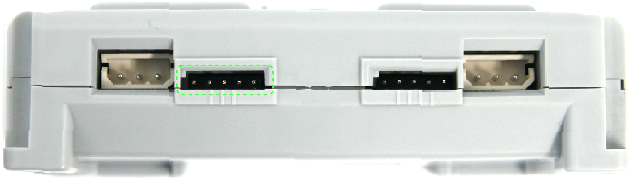
-
From any port the controller can read the position value of the servo motor. The range is from 0 to 0x03FF. The following illustration is with a servo motor in port 3.
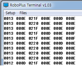
-
IR Sensor
Here you can learn how t o use the ADC of external ports.
- Prepare
- Connect the CM-530 to the PC via USB cable.
- IR Sensor (Connected to the external sensor No.1)
- Theory
-
The controller can change input analog signals into digital form. This example converts the motor’s analog position signal.
- The ANALOG MUX (74HC4052D) blocks impedance and converts voltage from 5V to 3.3V.
- The ADX MUX circuit combines signal from ADC_SELECT0, and ADC_SELECT1; SIG_ADC0 selects a signal from ADC1, ADC2, or ADC3 and feeds it into the microcontroller; SIG_ADC1 selects a signal from ADC4, ADC5, or ADC6 and feeds it into the microcontroller; then this signal gets converted into digital.
- Refer to controller’s port for port and pin number in 08 IR SENSOR\APP\src\main.c
-
- Source
int main(void)
{
  /* System Clocks Configuration */
  RCC_Configuration();
  /* NVIC configuration */
  NVIC_Configuration();
  /* GPIO configuration */
  GPIO_Configuration();
  SysTick_Configuration();
  /* ADC configuration */
  ADC_Configuration();
  GPIO_ResetBits(PORT_SIG_MOT1P,PIN_SIG_MOT1P);
  GPIO_ResetBits(PORT_SIG_MOT1M,PIN_SIG_MOT1M);
  //GPIO_ResetBits(PORT_LED_POWER, PIN_LED_POWER);

  while(1)
  {
    GPIO_SetBits(PORT_SIG_MOT1P, PIN_SIG_MOT1P);
    GPIO_ResetBits(PORT_SIG_MOT1M, PIN_SIG_MOT1M);
    GPIO_ResetBits(PORT_ADC_SELECT0,PIN_ADC_SELECT0);
    GPIO_ResetBits(PORT_ADC_SELECT1,PIN_ADC_SELECT1);
    uDelay(30);
    /* Start ADC1,ADC2 Software Conversion */
    ADC_SoftwareStartConvCmd(ADC1, ENABLE);
    //ADC_SoftwareStartConvCmd(ADC2, ENABLE);
    uDelay(5);
    IR_1 = (ADC_GetConversionValue(ADC1));
    GPIO_ResetBits(PORT_SIG_MOT1P, PIN_SIG_MOT1P);
    GPIO_ResetBits(PORT_SIG_MOT1M, PIN_SIG_MOT1M);
    TxDWord16(IR_1);
    TxDByte_PC('\r');
    TxDByte_PC('\n');
    mDelay(5);
  }
  return 0;
}
- Result
- Connect the IR sensor to port 1 and reading values ar displayed onscreen.
Read/Write Dynamixel
The location of DYNAMIXEL can be set and read. (For more details refer to DYNAMIXEL SDK)
- Prepare
- The controller and DYNAMIXEL are connected.
- This example is operated if DYNAMIXEL ID is 1.
- Theory
- DYNAMIXEL can be controlled by transmitting designated packet. The location of DYNAMIXEL can be controlled using provided library.
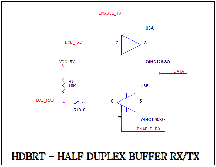
- The microcontroller and DYNAMIXEL comm are in USART channel 1
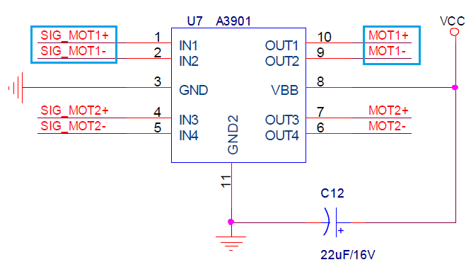
- the diagram below show a circuit for DYNAMIXEL comm for a half-duplex buffer.
-
Refer to controller’s port for port and pin number in 09 DXL READ_WRITE\APP\src\main.c
- Source
int main(void)
{
  /* System Clocks Configuration */
  RCC_Configuration();
  /* NVIC configuration */
  NVIC_Configuration();
  /* GPIO configuration */
  GPIO_Configuration();
  SysTick_Configuration();
  dxl_initialize( 0, 1 );
  USART_Configuration(USART_PC, Baudrate_PC);
  TxDString("\n\nDynamixel Read/Write example for CM-530\n\n");

  while(1)
  {
    bMoving = dxl_read_byte( id, P_MOVING );
    CommStatus = dxl_get_result();
    if( CommStatus == COMM_RXSUCCESS )
    {
      if( bMoving == 0 )
      {
        // Change goal position
        if( INDEX == 0 )
          INDEX = 1;
        else
          INDEX = 0;
        // Write goal position
        dxl_write_word( id, P_GOAL_POSITION_L, GoalPos[INDEX] );
      }
      PrintErrorCode();
      // Read present position
      wPresentPos = dxl_read_word( id, P_PRESENT_POSITION_L );
      TxDWord16(GoalPos[INDEX]);
      TxDString("   ");
      TxDWord16(wPresentPos);
      TxDByte_PC('\r');
      TxDByte_PC('\n');
    }
    else
      PrintCommStatus(CommStatus);
  }
  return 0;
}
- Result
- DYNAMIXEL is moved back and forth in the disgnated location, and the current location is printed through terminal.
Dynamixel Sync Control
Multiple DYNAMIXEL can be controlled by synchronization. (For more details refer to DYNAMIXEL SDK)
- Prepare
- The controller and DYNAMIXEL are connected.
- This example is operated when DYNAMIXEL ID is designated from 1 to 3 in order.
- Theory
- DYNAMIXEL can be controlled by transmitting designated packet. The location of DYNAMIXEL can be controlled using provided library.
- The microcontroller and DYNAMIXEL comm are in USART channel 1
- the diagram below show a circuit for DYNAMIXEL comm for a half-duplex buffer.
-
Refer to controller’s port for port and pin number in 10 DXL SYNC WRITE\APP\src\main.c
- Source
int main(void)
{
  /* System Clocks Configuration */
  RCC_Configuration();
  /* NVIC configuration */
  NVIC_Configuration();
  /* GPIO configuration */
  GPIO_Configuration();
  SysTick_Configuration();
  dxl_initialize( 0, 1 );
  USART_Configuration(USART_PC, Baudrate_PC);
  TxDString("\n\nDynamixel SyncWrite example for CM-530\n\n");
  for( i=0; i<NUM_ACTUATOR; i++ )
  {
    id[i] = i+1;
  }
  // Set goal speed
  dxl_write_word( BROADCAST_ID, P_GOAL_SPEED_L, 0 );
  // Set goal position
  dxl_write_word( BROADCAST_ID, P_GOAL_POSITION_L, AmpPos );
  mDelay(1000);

  while(1)
  {
    // Make syncwrite packet
    dxl_set_txpacket_id(BROADCAST_ID);
    dxl_set_txpacket_instruction(INST_SYNC_WRITE);
    dxl_set_txpacket_parameter(0, P_GOAL_POSITION_L);
    dxl_set_txpacket_parameter(1, 2);
    for( i=0; i<NUM_ACTUATOR; i++ )
    {
      dxl_set_txpacket_parameter(2+3*i, id[i]);
      dxl_set_txpacket_parameter(2+3*i+1, dxl_get_lowbyte(GoalPos));
      dxl_set_txpacket_parameter(2+3*i+2, dxl_get_highbyte(GoalPos));
      TxDByte_PC('\r');
      TxDByte_PC('\n');
      TxDWord16(GoalPos);
    }
    dxl_set_txpacket_length((2+1)*NUM_ACTUATOR+4);
    dxl_txrx_packet();
    CommStatus = dxl_get_result();
    if( CommStatus == COMM_RXSUCCESS )
      PrintErrorCode();
    else
      PrintCommStatus(CommStatus);
    GoalPos += 100;
    if( GoalPos > MAX_POSITION )
      GoalPos -= MAX_POSITION;
    mDelay(CONTROL_PERIOD);
  }
  return 0;
}
- Result
- Multiple DYNAMIXEL are moved back and forth in the designated location, and the current location is printed through terminal.
RC-100/ZIGBEE
The controller can be operated using RC-100.
- Prepare
- CM-530
- One pair of Zig-100/110
- RC-100
- Theory
- The controller can be controlled by RC100 remote controller equipped with Zig 100.
-
The microcontroller and RC-100 comm are in USART channel 5
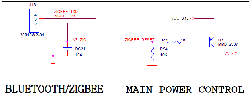
- The diagram above show Zigbee’s connector and power supply circuit.
- Refer to controller’s port for port and pin number in 11 RC100 ZIGBEE\APP\src\main.c
- Source
int main(void)
{
  /* System Clocks Configuration */
  RCC_Configuration();
  /* NVIC configuration */
  NVIC_Configuration();
  /* Configure the GPIO ports */
  GPIO_Configuration();
  SysTick_Configuration();
  zgb_initialize(0);
  USART_Configuration(USART_PC, 57600);
  GPIO_ResetBits(PORT_LED_POWER, PIN_LED_POWER);

  while(1)
  {
    if(zgb_rx_check() == 1)
    {
      RcvData = zgb_rx_data();
      TxDWord16(RcvData);
      TxDByte_PC('\r');
      TxDByte_PC('\n');
      if(RcvData & RC100_BTN_1)
        GPIO_ResetBits(PORT_LED_MANAGE, PIN_LED_MANAGE);
      else
        GPIO_SetBits(PORT_LED_MANAGE, PIN_LED_MANAGE);
      if(RcvData & RC100_BTN_2)
        GPIO_ResetBits(PORT_LED_PROGRAM, PIN_LED_PROGRAM);
      else
        GPIO_SetBits(PORT_LED_PROGRAM, PIN_LED_PROGRAM);
      if(RcvData & RC100_BTN_3)
        GPIO_ResetBits(PORT_LED_PLAY, PIN_LED_PLAY);
      else
        GPIO_SetBits(PORT_LED_PLAY, PIN_LED_PLAY);
    }
  }
  return 0;
}
- Result
- If Zigbee is connected normally, LEDs are turned on and off whenever the buttons of RC-100 is pressed.