Introduction
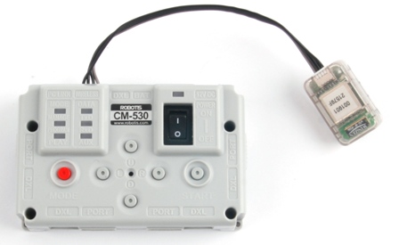
CM-530
Specifications
| Item | Description |
|---|---|
| Weight | 54g |
| CPU | STM32F103RE |
| Voltage Supply | Range : 6V ~ 15V Recommended : 11.1V (3S1P Li-Po) |
| Current Consumption | Standby : 50mA External I/O Max Current : 300mA Total Max Current : 10A(Fuse) |
| Operation Temperature | -5°C ~ 70°C |
| Internal I/O Device | Button x 5(Reset 1, Port 5) MIC for sound detection x 1 Voltage Sensor x 1 |
| External I/O Device | ROBOTIS 5-Pin Port x 6 AX/MX Series DYNAMIXEL Connector x 5 |
![]()
DANGER
(May cause serious injury or death)
- Never place items containing water, flammables, or solvents near the product.
- Never place fingers, arms, toes, and other body parts near product during operation.
- Cut the power off if the product begins to emit strange odors or smoke.
- Keep product out of reach of children.
- Check input polarity before installing wiring or cables.
![]()
CAUTION
(May cause injury or damage to product)
- Always comply with operating environment specifications including voltage, current, and temperature.
- Do not insert blades or other sharp objects during product operation.
![]()
ATTENTION
(May cause injury or damage to product)
- Do not disassemble or modify the product.
- Do not drop or apply strong impacts to the product.
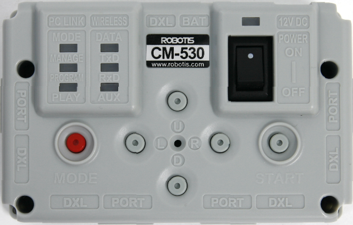
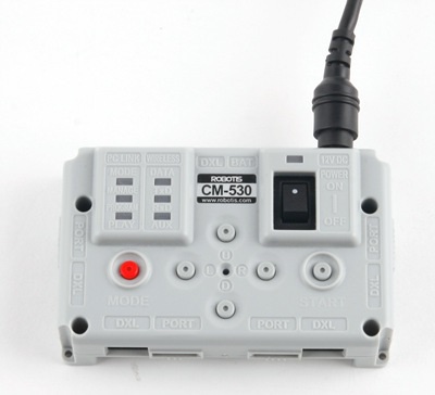
Layout
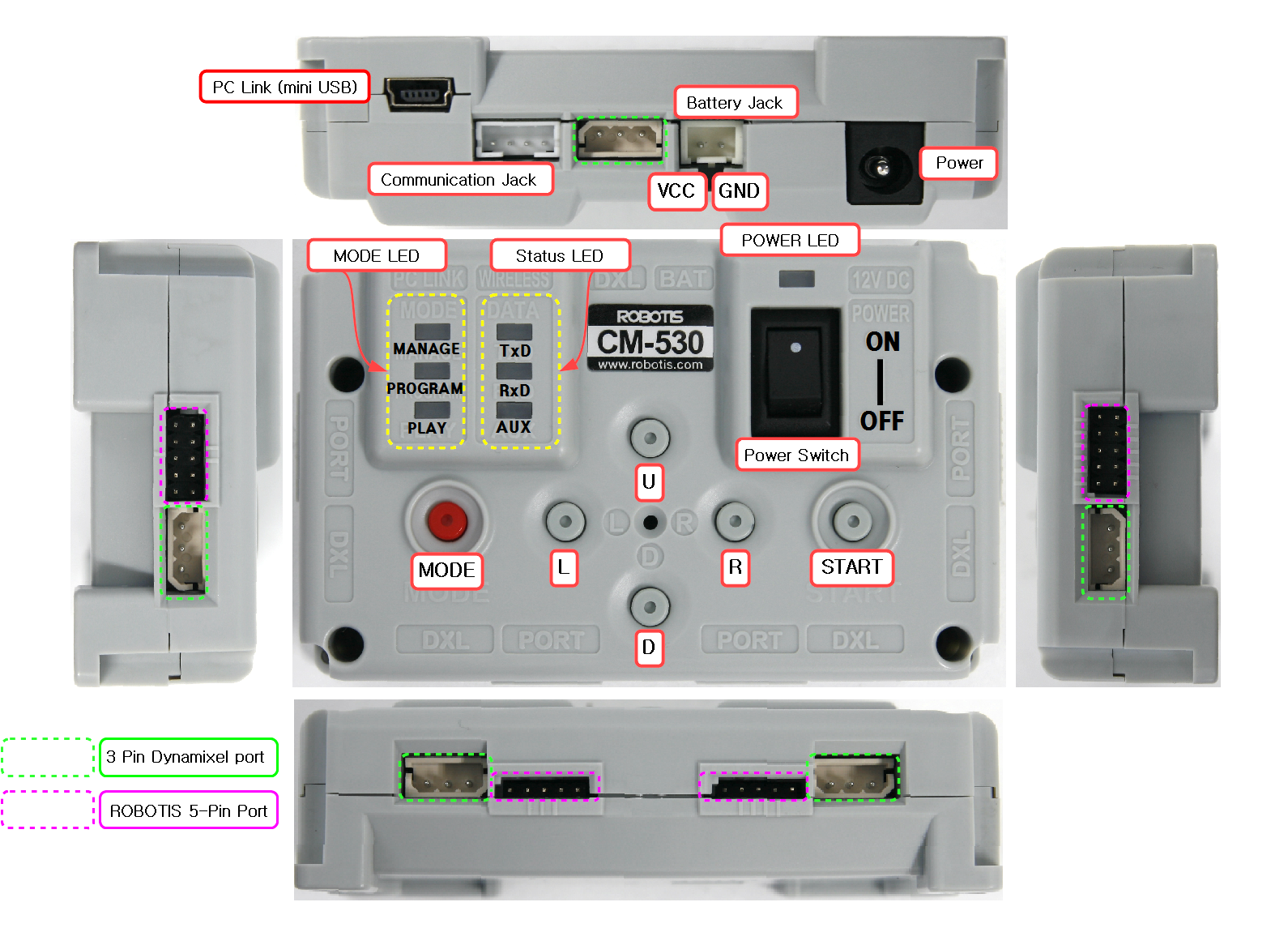
- PC Link (Serial Cable) : Used to connect the serial cable to the CM-530 and PC via USB. Used for communication with other PC or downloading task code.
- Communication Device Connection Jack : Used for wireless communicate with ZIG-110A, BT-110A, IR receiver modules or other boards
- Battery Jack : Used to connect with the battery.
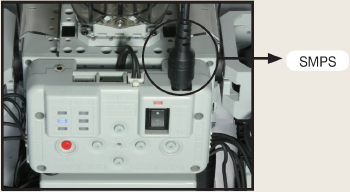
- Power Jack : Used to connect the SMPS power supply
- Power LED : ON and OFF LED status for the power
- Power Switch : Used to turn the robot ON / OFF.
- MODE Button : Used to change the operation mode of CM-530. Please read below for more information.
- START Button : Used to START selected mode. Please read below for more information.
- U / L / D / R Button : Used for input purposes when a program is playing. These buttons can be used to send commands to the robot.
- AX/MX Serise Bus Port : Used to connect the AX/MX DYNAMIXEL in a daisy chain method.
- ROBOTIS 5-Pin Port : Used to connect Distance Measurement Sensor, Touch Sensor, IR Sensor, and peripheral devices. The port numbers for each port are represented in bars such as I , II , III, IIII , IIIII , and IIIIII.
- Mode Display LED : LED to display current operation mode of CM-530; Detailed descriptions are provided as below.
[MANAGE]
- It displays DYNAMIXEL Management Mode is in progress.
- It is used to set or test the operations of CM-530 and AX-12A using RoboPlus Manager.
- It is automatically executed when RoboPlus Manager and CM-530 are connected.
[PROGRAM]
- It displays the motion edit mode is in progress.
- It is used when the motions are editted with RoboPlus Motion.
- It is automatically executed when RoboPlus Motion and CM-530 are connected.
[PLAY]
- It displays the task code mode is in progress.
- It is used after downloading the written code to CM-530 with RoboPlus Task.
-
The Start button must be pressed directly by the user to execute when PLAY LED flickers.
- Status Display LED : The LED represents the current status of CM-530. Detailed discriptions are provided as below.
- TxD : Turned on while CM-530 is transmitting the data to the outside.
- RxD : Turned on while CM-530 is receiving the data from the outside.
- AUX : Assigned LED to be used by the user in the program. It can be turned on or off using task code.
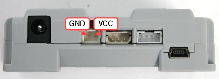
Pinout
Power
The pin composition of CM-530 Power is as below.
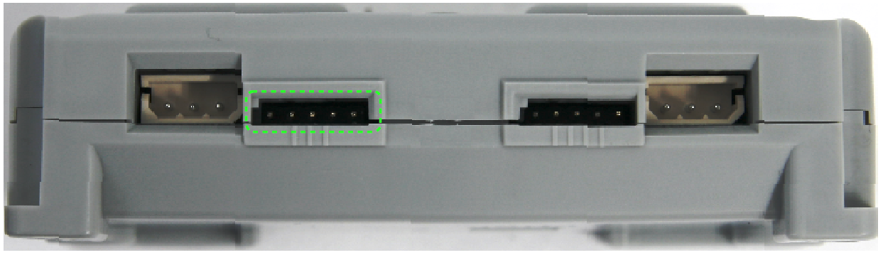
External 5-Pin Port
The pin composition of CM-530 external port is as below.
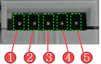
- OUT : 3.3V- Torque Possible (Maximum Allowed Current 0.3A)
- VDD (5V)
- ADC : The analog signals from the sensor made by the user can be read.
- GND
- OUT2 : 3.3V- Torque Possible (Maximum Allowed Current 0.3A)
Communication Device Connection Port
The functions on the pins of communication device connection port are as below.
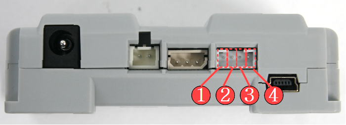
- GND : Ground Level (0v)
- VDD : Supply Voltage ( 2.7~3.6V )
- RXD : Receive Signal Terminal
- TXD : Transmit Signal Terminal
3-Pin Connector Port
The functions of pins on the 3-pin connector port are as follows. Please refer to AX-Series Pin Assignment for more information. Please be careful not to change the direction considering the angular part.

- GND : Ground Level (0v)
- VDD : Supply Voltage (It is equal to the voltage of battery)
- DATA : Data Transmission Pin
WARNING: To enhance user safety and to prevent proprietary risk or damage, be sure to check the pinout installed on DYNAMIXEL and the board. The Pinout of DYNAMIXEL may differ depending on a manufacturer of connector.
Connecting Power
The power is applied if the battery is connected to battery socket of CM-530 or if the power switch is set to ON after connecting SMPS to power jack socket. If the power is impressed, Power LED is turned on and one of the Mode Display LEDs flickers.
How to Operate
- Turning the power on : The power is turned on by moving the switch from OFF to ON. ※ If the power is not turned on in spite of moving the switch to ON, the batteries may have been discharged. Pleaser refer to Charging to recharge, or connect the power using SMPS.
- Start : Move to PLAY using Mode Button to operate robots. Press START Button to execute when the LED on PLAY flickers. ※ If START button is pressed, the LED on PLAY is not supposed to be flickering any more; that is the normal status of the execution.
- End : If you want to stop the executed operations, press MODE Button to get back to waiting mode stauts, or turn OFF the power using Power Switch.
- It is used to control DYNAMIXEL and the peripherals, and it can connect DYNAMIXEL(AX/MX DYNAMIXEL… etc.) and various parts of OLLO(Touch Sensor, LED Module, IR Sensor etc.).
-
Specific motions can be edited and saved through RoboPlus Motion. The saved motion (mtn file) can be always executed by RoboPlus Task, and also the motions of each part can be controlled by writing the task codes for control.
- RoboPlus Motion
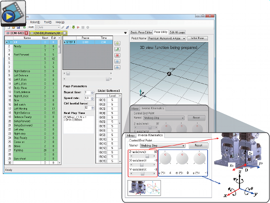
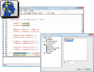
- RoboPlus Task
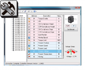
- RoboPlus Manager
- Embedded C The controller of CM-530 can be controlled in C language. Please refer to Embedded C for more information.
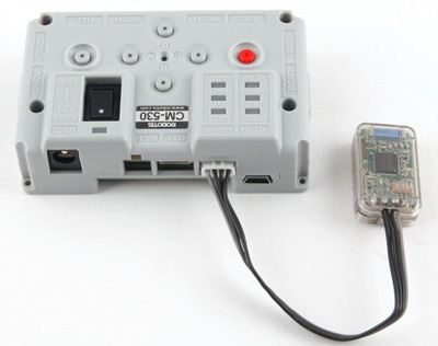
Connect to PC
PC Link(Serial Cable) of CM-530 and Serial Port of PC must be connected using download cable to communication with PC.

Wireless Communication
ZIG-110/BT-110/BT-410 Wireless Communication Module can be connected to CM-530.
Charging
You may obtain Lithium polymer batteries from www.robotis-shop-en.com.
If the robot alarm sounds off during operations then recharge the battery.
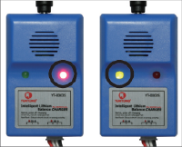
During charging the charger’s red LED turns on. When complete the green LED turns on.
- Take the battery out
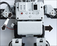
- Connect the charger
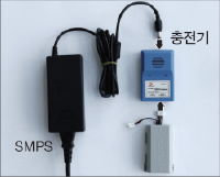
- Charge
Charging(Red LED), Complete(Green LED)
-
You can connect the robot to an external power source through SMPS.
-
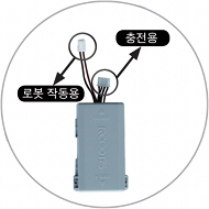
The battery is equipped with a connector to charge the battery and another to move the robot
Charging Time and Battery Life/Operating
Charging Time
- When fully discharged : 1~1.5 hour
- Leaving the battery fully discharged for too long may reduce its lifespan drastically.
- Time to charge the battery depends on the status of the battery(If the charging time or battery life becomes too short, you may need to replace your battery).
Caution
- Do NOT keep the battery connected with a robot or a charger.
- If you will not use the battery for a long time from now on, please keep it HALF-CHARGED.
- Do NOT put the battery with an environment with high temperature or humidity.
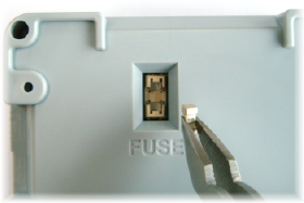
Fuse Replacement
The fuse in the CM-510/CM-530 prevents it from overloading,which can damage the circuit.
If the CM-510/CM-530 does not turn on with the battery but turns on when connected to the SMPS, replace your fuse.
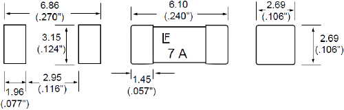
※ The size of the fuse is shown below. Use a 125V/5A~10A fuse.
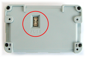
※ How to replace the fuse
-
Find the fuse on the back of the CM-510/CM-530.
-
Use a pincette to replace the fuse with a new one.