Introduction
The ROBOTIS OpenCM is a development Software and download tool for the OpenCM9.04 embedded board.
Sources of the ROBOTIS OpenCM are released under licenses of their respective authors.
Copyright (c) ROBOTIS Co., Ltd. Modified or newly-created codes are released under the GNUGPL or LGPL licenses.
For more information on the OpenCM9.04 refer to the Appendix section of the e-manuals.
WARNING : OpenCM IDE is not updated anymore. It is recommanded to use Arduino IDE as OpenCM IDE isn’t maintanined anymore.
ROBOTIS OpenCM Software Download
OpenCM9.04 uses the ROBOTIS OpenCM Integrated Developmental Environment (IDE) to allow users to program with ease.
The download link for the ROBOTIS OpenCM IDE can be found below:
- [Windows XP, Vista, 7, 8] 32bit/64bit : Download
- [Mac OS X] Tested in OS X 10.12.2 : Download
- [Linux 64bit] Tested in Ubuntu 12.04 : Download
- [Linux 32bit] Tested in Ubuntu 10.10 : Download
Getting Started
Install Software
Windows
Prepare the OpenCM9.04 and USB cable
For the cable you must prepare an Android phone/pad Micro-B type USB cable. (This is included as a component of the package for the B type, and for the A type you must purchase through an accessory kit. Android smartphone cable is supported.)

Micro-B USB cable : same as Android smartphone
Download the Windows release for ROBOTIS OpenCM IDE
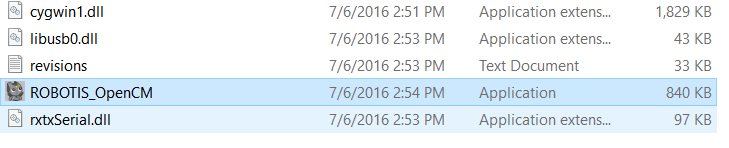
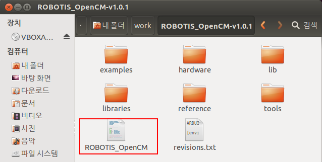
Download the latest version from the ROBOTIS E-manual(support.robotis.com) site and unzip the file in an adequate directory, which will contain the execution file ROBOTIS_OpenCM.exe and the USB driver folder(\drivers) as shown below.
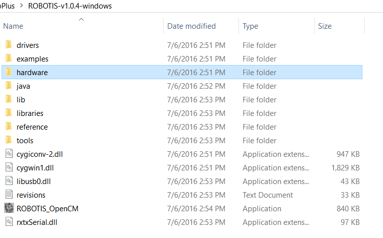
Directory structure after unzipping the file
Note that the ROBOTIS OpenCM is a portable program that only needs to be unzipped and executed without the need for any separate installation process. If you wish to remove the program, you simply need to delete the directly fully.
Connect the OpenCM9.04 to the PC
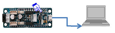
For the installation of the USB driver, simply connect the OpenCM9.04 to the PC using the USB cable as shown below.
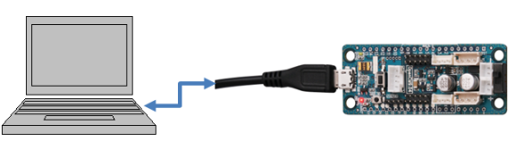
Figure 2.4.1-4 Connecting the OpenCM9.04 to the PC
However we do recommend you avoid connecting to a USB hub that is in use with many other USB devices, and instead you connect to the PC directly. There can be rare cases in which if there is not enough electric current from the USB hub then the download can fail.
Driver Installation
For Window 8 or 10, go to “PC settings -> Update and recovery -> Recovery -> Advanced startup -> Troubleshoot -> Advanced options -> Startup Settings -> Restart -> Select 7) Disable driver signature enforcement, and then restart” and then install using Run as administrator.
In the previous step, connecting the OpenCM board to the PC will make a device called “ROBOTIS Virtual COM Port” appear in the Device Manager.
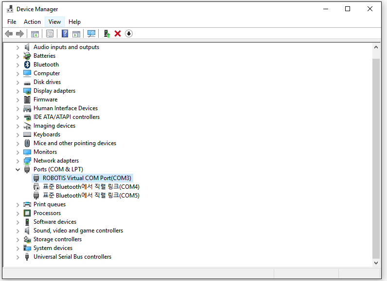
Right-click on that device and select “Update Driver Software”.
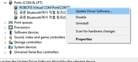
Next select “Browse my computer for driver software”.
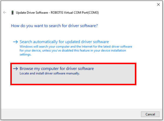
Click on “Browse” and select the directory that you unzipped above(ROBOTIS\drivers).
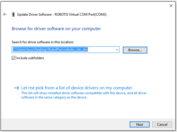
Click Next and the installation proceeds.
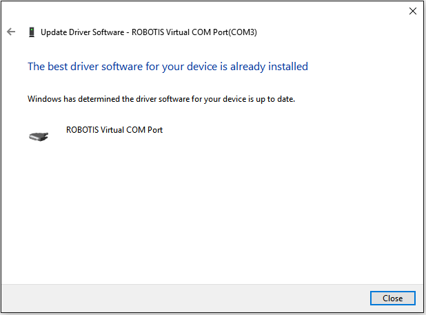
If the USB driver is installed successfully, a message will appear that says “Windows has successfully updated your driver software” as shown below.
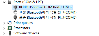
At this stage it is important to check in the Device Manager what COM Port number the ROBOTIS Virtual COM Port has just been installed as.
Connecting to another USB port may change the COM Port number so if you connected to another port then check again and proceed to download.
Run ROBOTIS_OpenCM.exe
In the unzipped directory(\ROBOTIS) double-click on the file ROBOTIS_OpenCM.exe.
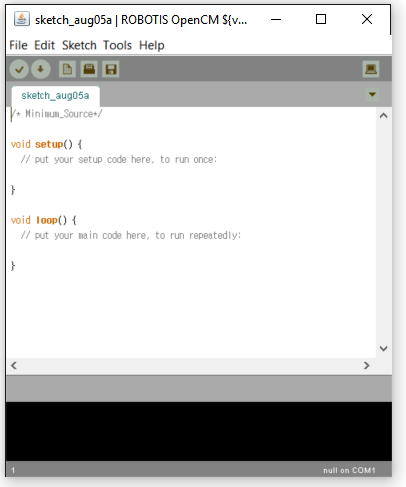
This will execute the ROBOTIS OpenCM tool as shown below.
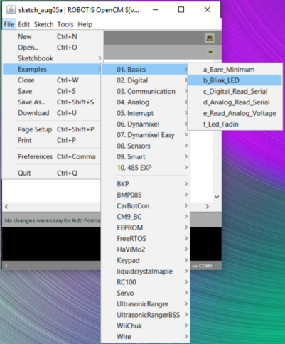
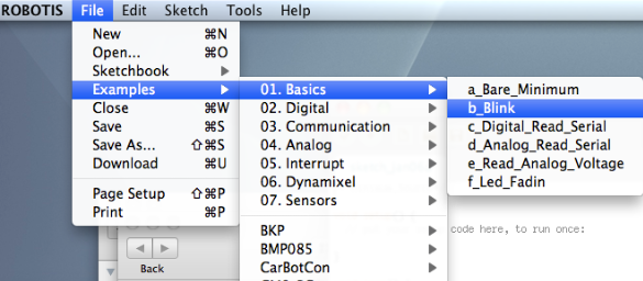
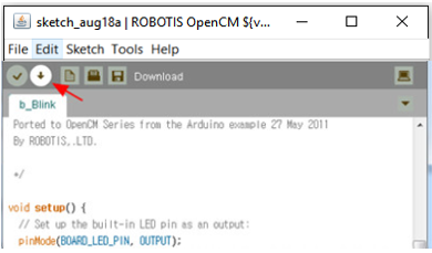
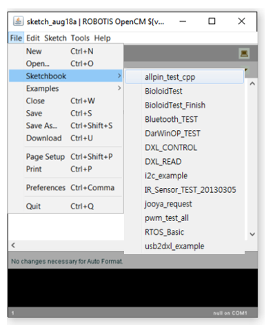
Open the Example Blink
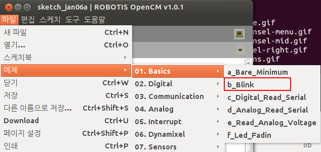
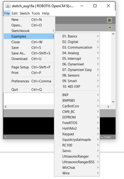
Go to File → Examples → 01.Basics → b_Blink
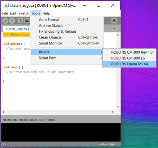
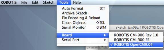
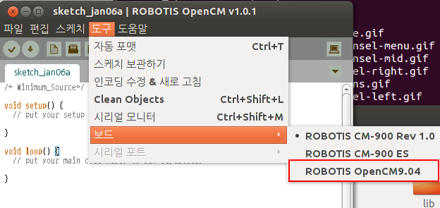
Select the Board
In Tools → Board, select ROBOTIS OpenCM9.04.
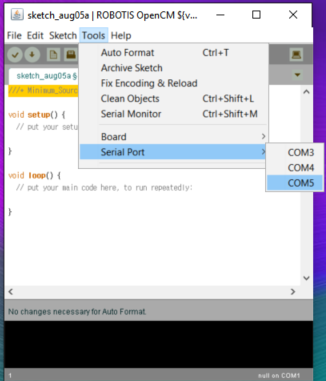
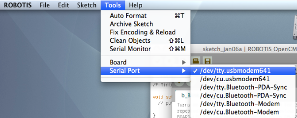
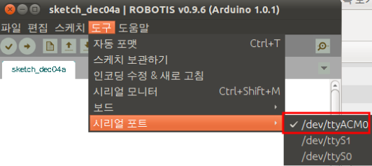
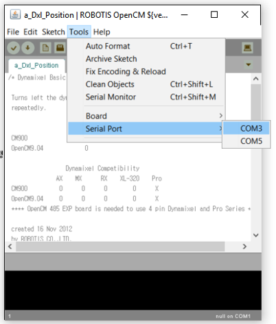
Select the Serial Port
Make sure you select the COM Port number that you checked in the previous step.
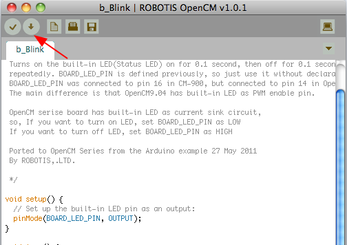
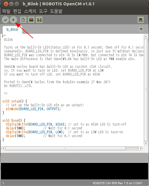
Proceed to Download
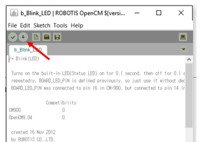
Click on the Download button as shown below. As the download begins the board’s green LED is continuously turned on. Once the download is complete the board resets and the Blink example is executed, and the LED blinks.
NOTE : If the power turns on for the board and the green LED is continuously turned on then restart the Download. Please refer to the Emergency Recovery Mode(Force Download) section.
MAC OS X
Download the Mac OS X release for ROBOTIS OpenCM
Download the installation image file(dmg) for Mac OS X from the E-manual.
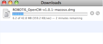
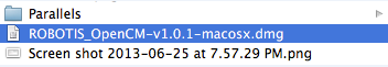
When the download finishes, double-click on the dmg file below and proceed to Mount.
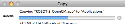
After mounting, when an installation window appears, click on the Robotis icon with the mouse and drag it to Application.
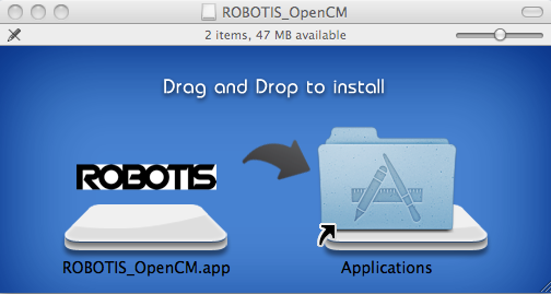
Then the installation will proceed as below.
Run the ROBOTIS OpenCM
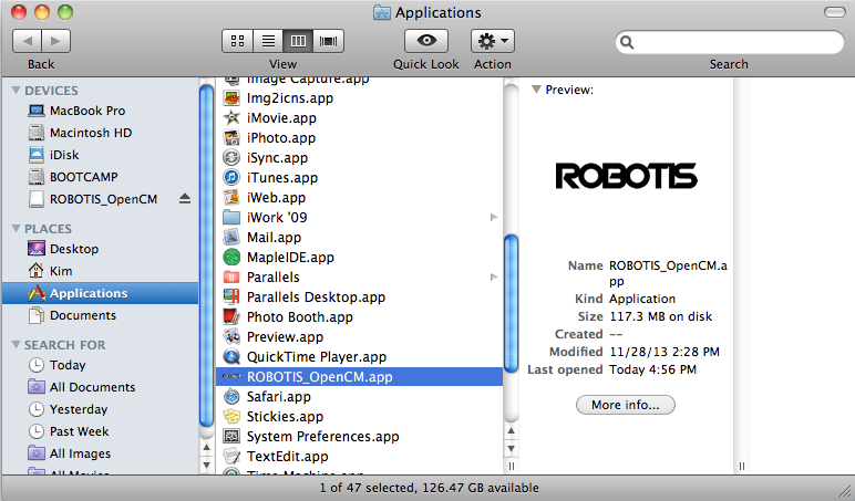
Using Finder, look in the Application folder to find the ROBOTIS.app application package and double-click on it to run the program.
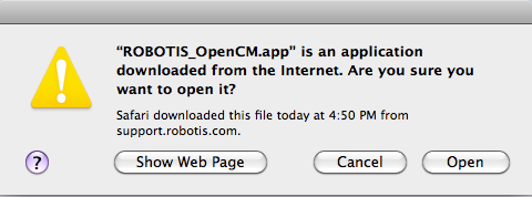
As in the figure below, select the Open button.
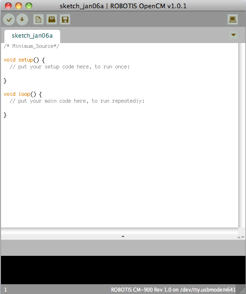
The ROBOTIS OpenCM is executed as shown below.
Open the Example Blink
Go to File → Examples → 01. Basics → b_Blink
Select Board
Select ROBOTIS OpenCM9.04.
Select Serial Port.
Select tty.usbmodemXXX. The number on the end is different for each PC.
Proceed to Download
Click on the Download button as shown below. As the download begins the board’s green LED is continuously turned on. Once the download is complete the board resets and the Blink example is executed, and the LED blinks.
NOTE : If the board’s green Status LED does not turn on even after clicking on the Download button, press on the User button and while keeping the button pressed connect the USB to the PC.
NOTE : If the power turns on for the board and the green LED is continuously turned on then restart the Download. Please refer to the Emergency Recovery Mode(Force Download) section.
Linux
Download the Linux release for ROBOTIS OpenCM
If the Linux you are using is 32bit then download the Linux 32 bit package, and if it is 64bit then download the Linux 64 bit package from the e-Manual.
After downloading, use the following command to unzip the file. The description below is an example for when using 32bit.
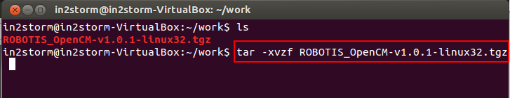
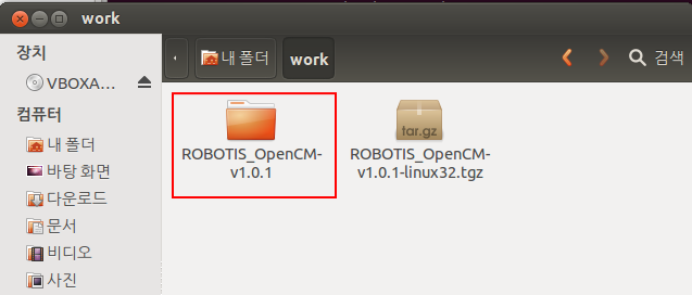
If you unzip the file it will create a ROBOTIS folder as shown below.
Install JRE(Java Runtime Environment)
Same as for Arduino, the ROBOTIS OpenCM tool is a program that has been developed using Java and therefore requires JRE(Java Runtime Environment). The Windows package includes JRE inside but the Linux version does not include it.
If it is installed then proceed to the next step. The way to check if JRE is installed is to use java –version in Terminal as shown below.
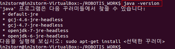
If you get a message as above then you need to install JAVA JRE(Java Runtime Environment) or JDK.
Here is how you install openjdk-7-jre-headless.
$sudo apt-get install openjdk-7-jre
Now that Java JRE has been successfully installed, you can run ROBOTIS OpenCM.
Install i386 Library (Linux 64bit)
In order to use in Linux 64bit OS, you need to install ia32-libs.
$sudo dpkg –add-architecture i386
$sudo apt-get update
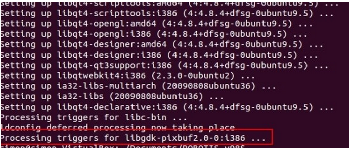
$sudo apt-get install ia32-libs
If the installation completes successfully, the Processing trigger runs properly as shown below.
Run ROBOTIS OpenCM
As shown below, double-clicking ROBOTIS_OpenCM or entering ./ROBOTIS_OpenCM in Terminal and pressing Enter will run the program.
Click on the Execute button.
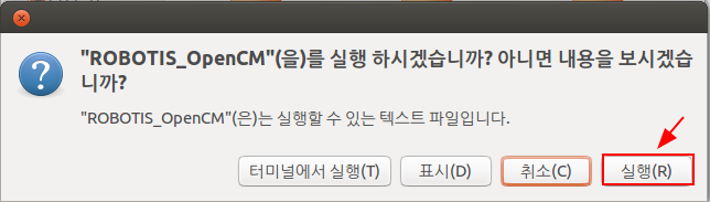
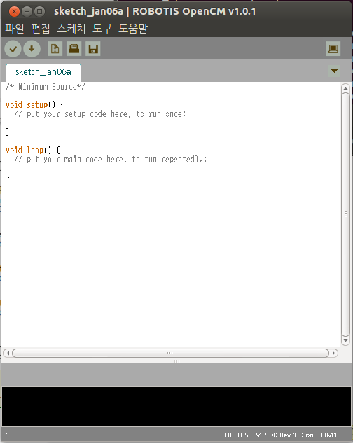
Then the program will run as shown below.
Open the Example Blink
Go to File → Examples → 01. Basics → b_Blink
Select Board
In Tools → Board, select ROBOTIS OpenCM9.04.
Select Serial Port
The serial port is shown as ttyACMX, where X is a different number for each PC.
The Linux/Mac OS X releases have the USB CDC Driver included in the kernel, so unlike the Windows release you can run the program right away without the need to install a driver separately.
Proceed to Download
Click on the Download button as shown below.
As the download begins the board’s green LED is continuously turned on. Once the download is complete the board resets and the Blink example is executed, and the LED blinks.
NOTE : If the board’s green Status LED does not turn on even after clicking on the Download button, press on the User button and while keeping the button pressed connect the USB to the PC.
NOTE : If the power turns on for the board and the green LED is continuously turned on then restart the Download. Please refer to the Emergency Recovery Mode(Force Download) section.
Run Program
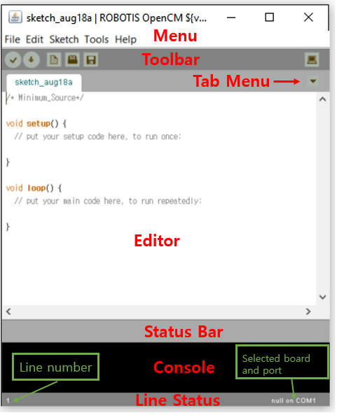
If you run the program the following screen appears.
| Item | Description |
|---|---|
| Menu | You can select from File, Edit, Sketch, Tools, and Help. |
| Toolbar | You can select from a list of shortcut icons of frequently used functions. |
 |
Executes only the compilation and prints a message on the status bar or console stating whether it was fail or success |
 |
Executes compilation and proceeds to download right away. Make sure the board is connected when using this function |
 |
Creates a new file |
 |
Opens a file |
 |
Saves the current file |
 |
Runs the serial monitor |
| Editor | This is the field where you edit the source. |
| Status Bar | This is the field where it shows the progress of the requested function visually. |
| Console | Shows the current cursor location’s line number and the selected board and COM Port. |
| Tab Menu | This is the menu that you select when adding or removing a tab. |
A Look at Some Examples
The ROBOTIS OpenCM IDE provides some simple examples of functions provided by the OpenCM hardware board, and you can check the File (e.g.)Examples menu to see the various examples shown below.
Code Editing Function
Auto Highlight Function
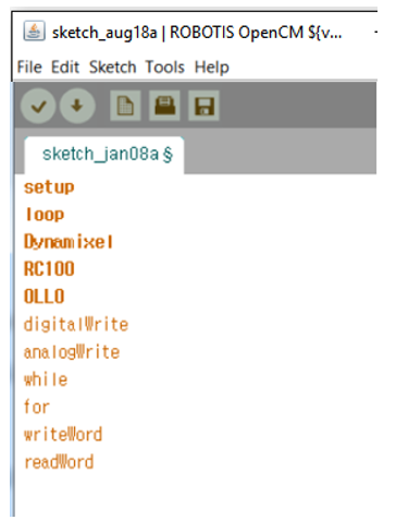
When typing code, registered keywords will be highlighted in yellow or blue automatically (as opposed to the usual black) as shown below.
Registered API will change colors as shown below, so that you can check if the name of the API you are trying to use is typed correctly.
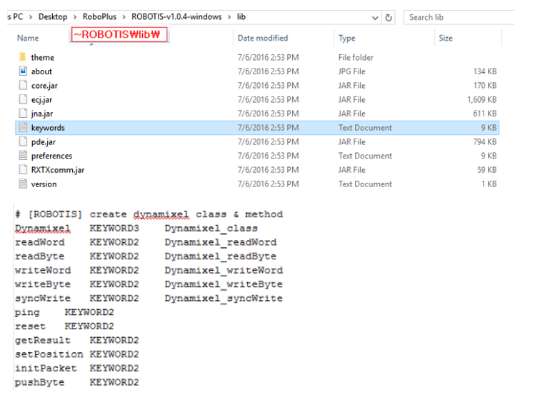
You can also modify or add to the Auto highlight function at any time in the keyword.txt file located in the directory below.
Using the Auto Format Function
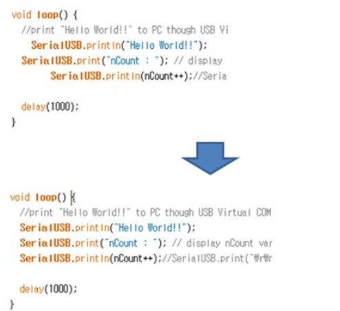
By using the function in Tools → Auto Format, codes that have been typed jumbled or messy are automatically organized neatly.
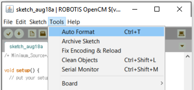
Codes such as below are automatically organized neatly by pressing Ctrl+T.
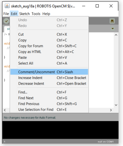
Adding and Removing Comments
Select Edit → Comment/Uncomment as shown below or press the hotkey Ctrl+/ to comment the entire line, and press the hotkey again to uncomment the line.
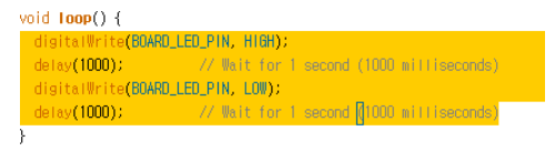
If you select a block as shown above and then press Ctrl+/ it will comment the entire block as shown below.
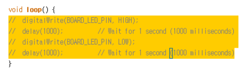
If you press Ctrl+/ again it will uncomment the selected lines.
Increase and Decrease Indent
If you select Edit → Increase Indent/Decrease Indent you can control the indentation level from the current cursor. You can also press the hotkeys Ctrl+} to move one tab to the right, or press Ctrl+} to move one tab to the left.
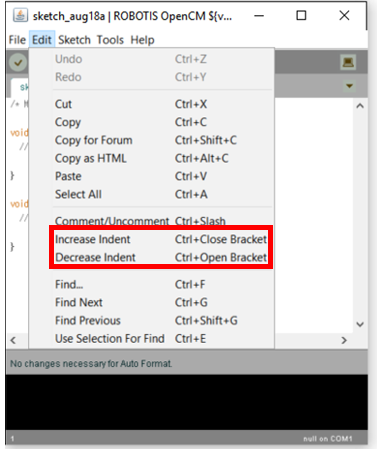
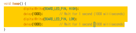
Pressing Ctrl+} repeatedly will move the cursor to the right one tab at a time as shown below.
Compile and Download
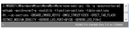
After you write your code it is useful when programming to use the Compile menu in order to check that the code you wrote is grammatically correct and has no errors.
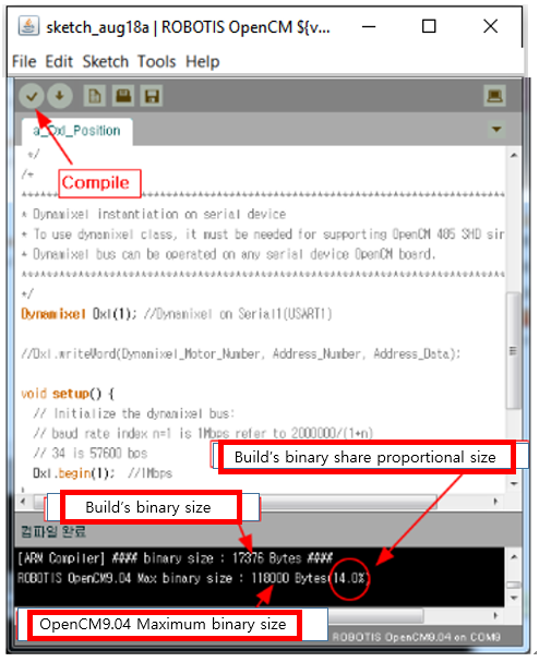
If the build is successful then in the status window below in the build’s binary size section it will show the maximum binary size, and the share proportional to the size as 0%.
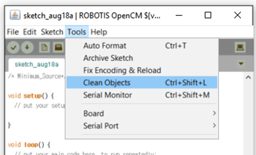
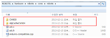
If you have modified the codes in the Core directory shown below, you must delete the Object files that were previously created.
ROBOTIS\hardware\robotis\cores\robotis
Do this by selecting the Tools → Clean Objects menu and then build again. It will take a long time to build the first time, but from the second time on it will be fast again since it will reuse the Object files from the first build.
The Object files are saved in each corresponding board directory inside the Core directory shown below.
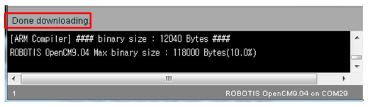
If the whole code is compiled properly with no errors you can now download. Simply click on the down arrow and it will compile and download all at once.
When the download finishes successfully there will be a message that says Done downloading in the status bar and the downloaded code will be executes directly in OpenCM9.04.
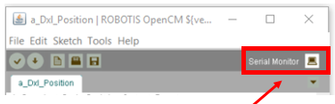
Using the Serial Monitor
ROBOTIS OpenCM provides a terminal program, similar to Windows’s hyper terminal or TeraTerm, by default as an Add-on program.
If you wish to communicate with the selected COM1 port then click on the serial monitor icon located on the upper-right side of the toolbar to open the serial monitor. You can also use the hotkey Ctrl + Shift + M to open the serial monitor.
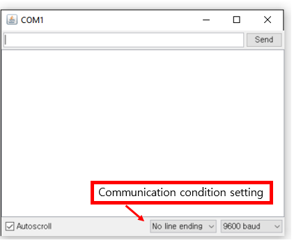
Precautions Regarding the Serial Monitor
When OpenCM9.04 is downloading, USB communication will not be available. Do not open the serial monitor when downloading is in progress. ( If it is a different COM port then it does not matter.)
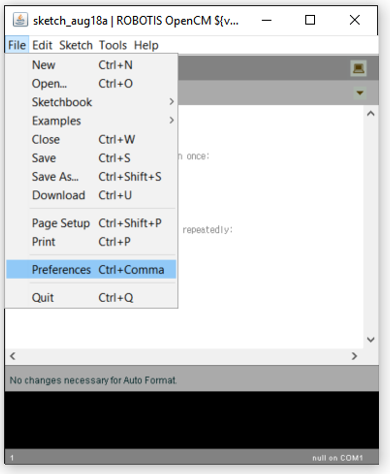
Preferences
Manage your settings preferences in File → Preferences.
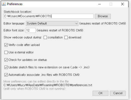
-
Sketchbook location : This is the user’s default work directory. Sketch files will be saved and opened from this directory.
-
Editor language: This changes the font of the program to a different language.
-
Show verbose output during : If you check Compilation then it will show a detailed output during the compilation process.
If you check Download then it will show a detailed output of the download process, after the compile has finished.
Compile and download can become slower when using this option, so we recommend you do not use it unless it is essential to use it.
Libraries
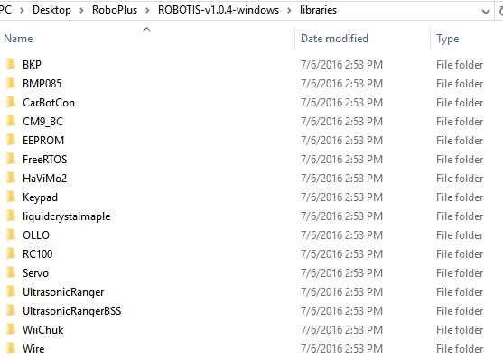
Installing Libraries
The installation method of libraries is the same as for Arduino. The library’s path is inside the IDE folder as libraries. ( ROBOTIS\libraries)
In the case of Mac, access the path below.
Documents/ROBOTIS/libraries
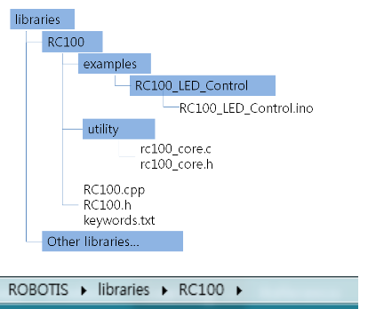
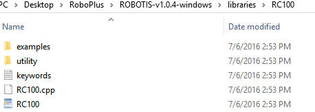
As above, organize the libraries folder so that inside there are files RC100.cpp, RC100.h with the same name as the folder RC100. You can put in code written with C file in the utility folder.
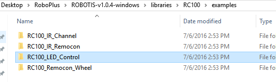
The examples folder is for sketch examples composed of the corresponding library. Examples are also organized as folders, and the folder name and the ino file name must be the same to be recognized.
Recovery Mode
If you are unable to download and the message “Board is not responding” shows up, please try using the recovery mode to force the download.
If you force the download once, the board should be recovered and normal downloads will be possible again.
Hold down the User Button on the OpenCM9.04 and connect the board to a PC using an USB cable.
Please have any other power source disconnected, and just connect to the USB while having the User Button held down.
Hold down the User Button when entering recovery mode.
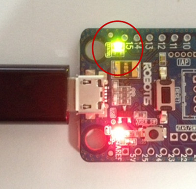
When successful, the green LED should stay on as shown in the image below. When the download is completed the board will reset and the LED will turn off.
If unable to download, you must remove any code that may disturb the USB interrupt in the code you wrote.
Examples
EEPROM(Flash)
In the CPU of EEPROM(Flash) Library OpenCM9.04, which is STM32F103CB, there is a 128kbyte flash memory.
The flash memory is where we save the programming in binary format and also run it. The flash memory is a non-volatile memory so even if the power is turned off the saved data does not disappear.
However flash reads and writes data by unit of a page so it can be relatively inconvenient for saving one or two bytes.
However its speed is fast. Therefore in OpenCM9.04 we have created a separate library called the EEPROM emulator to save user data in the unit of bytes.
Example
#include "EEPROM.h"
int i;
EEPROM CM9_EEPROM;
void setup(){
  CM9_EEPROM.begin();
  Serial2.begin(57600);
  Serial2.println("##### Start OpenCM9.04 EEPROM Memory Test ##############");
}
void loop(){
  delay(1000);
  for(i=0;i < 10;i++){
    Serial2.print("EEPROMExample = ");
    Serial2.println(CM9_EEPROM.read(i), HEX);// read data from virtualaddress 0~9
  }
  if(Serial2.available()){
    Serial2.read();
    Serial2.println("******************EEPROM Writing Start *******************");
    for(i=0; i<10;i++){      CM9_EEPROM.write(i,i*2);//
      write i*2 to virtual address 0~9
    }
  }
}
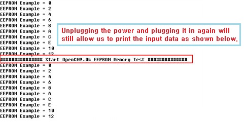
If you compile the code above and download it, it will read the values of the EEPROM virtual addresses from 0~9 through Serial2 as shown below.
Since there are no data all values will be printed as 0xffff.
In contrast with the BKP, the initialization of the flash memory will set all bits to 1.
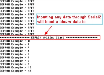
Therefore 0xffff is printed. And pressing any key will input a value between 0~12 to the virtual addresses 0~9.
Now press the Reset button to restart.
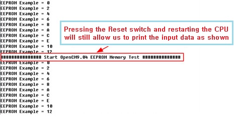
Now we unplug the power and plug in again to check.
Sensor Module
All Robotis sensor modules can be connected to 5-pin ports. Please refer to the OpenCM9.04 Hardware Manual for the connection method.
For the A-type you will need to separately solder the 5-pin connector, but for the B-type and C-type the 5-pin connector will already be embedded.
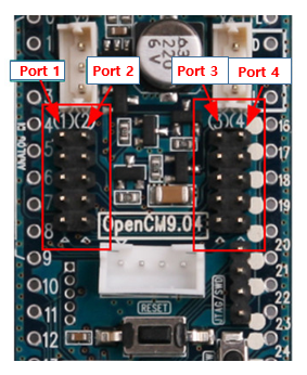
Please note that the pins assigned to the 5-pin are also shared with the 40-pin IO on both sides, so in the header you must not use the IO pins assigned to the ports used below.
For example, if you connect the IR sensor to Port 1, you must not use Pins 2, 6, and 7 in the header.
IR Sensor Module
-
Connectivity
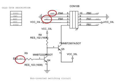
The way it works, as explained in the E-manual, is if High is given to SIG2(MOT+), the transmitter LED is turned on and its infrared is detected by the detector LED and is shown as ADC.
It is recommended that you connect the infrared sensor module to the Ports 1, 4 of SIG2 that have a transistor circuit. Ports 2, 3 will have a low ADC value.
The figure below shows when it is connected to Port 1. The direction for the connector is to connect the gray cord to the USB.
You can read the maximum value of the ADC value if you read it after approximately 10~15us. And the properties of the ADC values that can be detected according to their distance are shown below, so this must be taken into consideration for use.
It is not possible to detect objects that are farther than 15cm and object that are too close will reflect the infrared and the angle entering the detector LED will not be valid and result in a section that the sensor values will fall.(This corresponds to the section between 0~1.5cm) -
Confirming Operation
Open ROBOTIS OpenCM’s Example –> 07. Sensors –> IR_Read.
After downloading, open the serial monitor and place the object(maximum when white) close and you will be able to see the ADC values as shown below.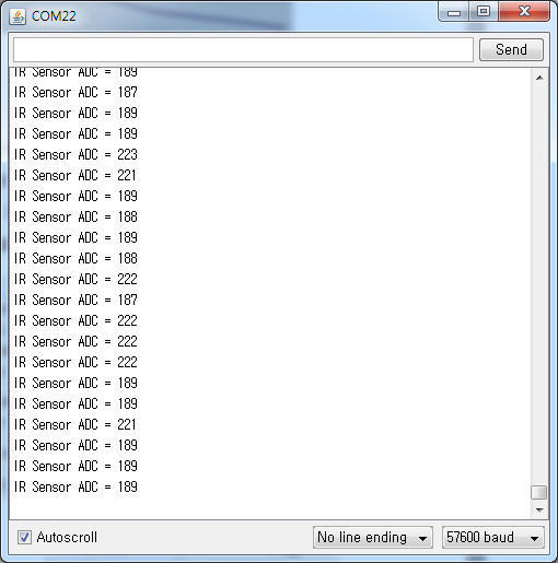
-
Operation Code
The IR sensor can perform IR sensing as long as it controls the pin that corresponds to the SIG2 and the ADC port. The OLLO library is already coded with this principle.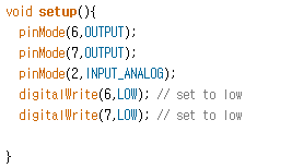
Check that Pins 2, 6, 7 are assigned to Port 1. In setup(), initialize Pins 6, 7 that are assigned to SIG1,2 to LOW and initialize Pin 2 to analog input.
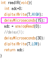
In function readIR, set SIG2(Pin 7) as HIGH to turn the transmitter LED as ON and if you read the analog value after 15us you can read the optimal ADC value.
And if you send SIG2 again as LOW then one cycle will be finished. It does not matter if there is nothing 30us afterwards.
The OLLO library is already coded with this principle so you can easily use it.
DMS Sensor Module
-
Connectivity
By default, you approve voltage using the 3 middle pins of the 5 pins and afterwards read the ADC value to utilize it.
It has the advantage that even if the color and reflectivity change compared to the infrared sensor, there is virtually no change to the output value corresponding to the distance.
There is no difference connecting to any of the 5-pin sensor ports of OpenCM9.04.
The DMS sensor does not use SIG1, 2 so it does not distinguish ports. Below it was connected to Port 2 and the example code is explained based on Port 2. -
Confirming Operation
In File –> Examples –> 07. Sensors, you can download example OLLO_DMS_Read and check using the serial monitor.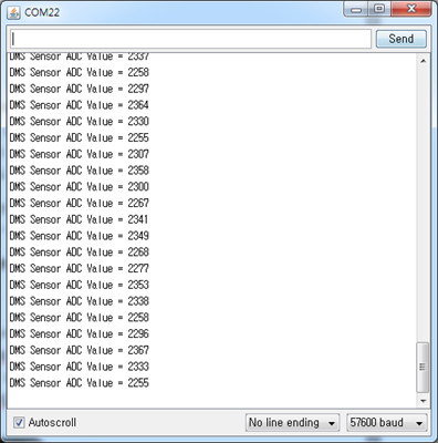
-
Operation Code
Sensors such as the DMS sensor module which are comprised of 3 pins from the 5 pin only need to keep on Reading the analog input. They do not need a separate initial code.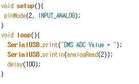
Gyro Sensor
-
Connectivity and Sensor Internal Structure
The Robotis gyro sensor can also be connected to Pin 5 of OpenCM9.04 to measure the angular speeds of X, Y (rotational acceleration).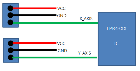
Connect the gyro sensor module of OpenCM9.04 to Pins 1 and 2 of the 5-pin port. Connect the X-axis pint to Port 1 and the Y-axis pin to Port 2 as shown in the connectivity below.
-
Operation Code
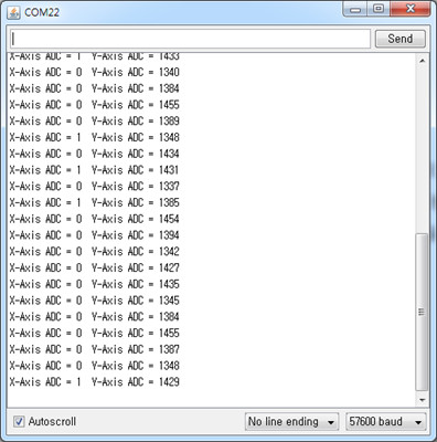
Download from Examples -> 07. Sensors -> OLLO_Gyro_Read and open the serial monitor to check the rotational acceleration of the X- and Y-axis in ADC as shown below.
Initialize Port 1 connected to the X-axis pin and Port 2 connected to the Y-axis pin and in the loop, read the ADC value of the rotational acceleration of the X- and Y-axis in a 60ms cycle.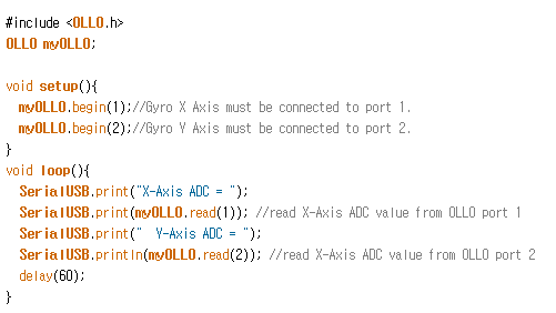
As for the DMS sensor module, you simply need to read the analog pin value from the loop.
LED Module
-
Connectivity and Internal Structure
The LED module is not a sensor module but simple a module to use 2 LED’s as a display format.
By looking at the circuit diagram you can tell that it is being controlled in a Current Sink method where MOT+- will be OFF when HIGH, and ON when LOW.
The SIG2 pins of Ports 1 and 4 of OpenCM9.04 does not turn LOW so there is a restriction in using the LED module, so use Ports 2 and 3 of the 5-pin ports. The figure below shows an example of using Port 3 to connect the LED module. -
Confirming Operation
In File -> Examples -> 07. Sensors, download and run example OLLO_LED_Blink and you will see that both LED’s from each side will blink alternatively.
The LED module does not need the ADC pin so you only need to use pins SIG1 and 2. You can use the LED module by initializing Port 3 in setup() as shown below.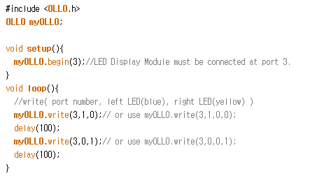
Touch Sensor
-
Connectivity and Internal Structure
The touch sensor works by detecting whether it has been touched, just as a button, when it is simply pressed from the top. You can also use it simply as a button.
The circuit diagram is also nothing more than a frequently used button circuit. When the button is pressed it returns HIGH and when the button is released it returns LOW.
You connect it to Port 2 of OpenCM9.04. -
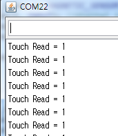
Operation Code
Download OLLO_TOUCH_Read from the OLLO library and open the serial monitor to check the result. 1 means the button is not pressed, and if the button is pressed than the value 0 will be output.
The touch sensor only uses the middle 3 pins of the 5 pins as well. We recommend using the ADC pin by declaring it as a digital input.
Since the touch sensor does not have an internal Pull-down circuit you must define INPUT_PULLDOWN as a Pull-down option. The OLLO library will internally initialize the pins of the 5-pin sensor in this way.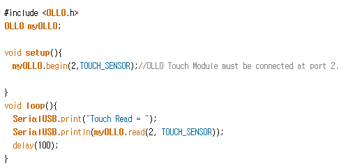
Digital I/O
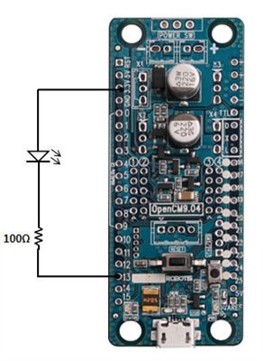
Connect the LED to Pin 13.
Connect the LED and resistor to OpenCM9.04 as shown below. Connect to Port 13.
For digital output you must use pinMode(13, OUTPUT) in setup() to set Pin 13 as OUTPUT. And use the function digitalWrite() to assign HIGH/LOW value.
digitalWrite(13, HIGH); //Outputs HIGH to Pin 13.
digitalWrite(13,LOW); // Outputs LOW to Pin 13.
When Pin 13 is assigned as LOW, it becomes a GND(negative terminal) and an electric current is formed so the LED turns on. On the contrary, if Pin 13 is assigned as HIGH it becomes 3.3V and there is no electric current formed so the LED turns off. This is the principle by which you can write a sketch code that will make the LED blink.
void setup(){
  pinMode(13, OUTPUT);
}
void loop(){
  digitalWrite(13, HIGH);
  delay(100); //delay of 0.1 second
  digitalWrite(13, LOW);
  delay(100); //delay of 0.1 second
}
You will see the LED blink every 0.1 second.
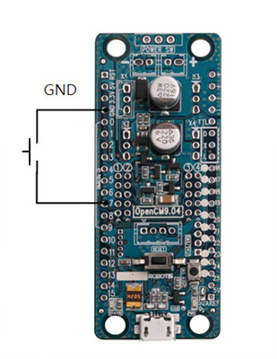
Let us make the Status LED blink.
In OpenCM9.04 you can even test using the green Status LED built-in to the board without having to connect the LED as in the example above.
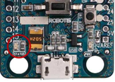
The Status LED is connected to Pin 14 and you can use the predefined function BOARD_LED_PIN to control it. This provides the advantage that if you write a sketch code using BOARD_LED_PIN then even if the board is changed you do not have to modify the code.
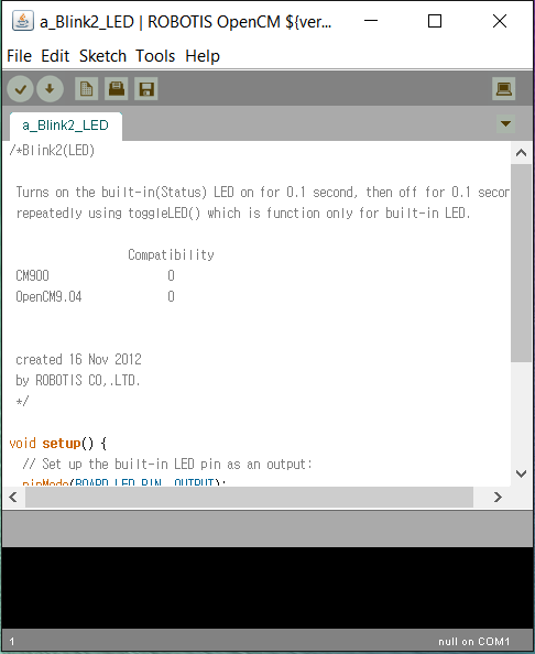
Open an example file by selecting File –> Examples –> 01. Basics –> b_Blink_LED.
If you download it then the green Status LED will blink.
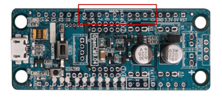
Let us receive a digital input in Pin 7.
Connect the button and pull-down resistor as shown below. Use Port 7 to receive the digital input.
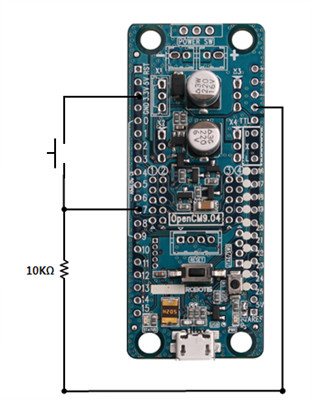
For digital input on the I/O Pin of OpenCM9.04 you must use pinMode(7, INPUT) in setup() to configure Pin 7 as INPUT. Then receive HIGH/LOW values with the function digitalRead() as shown below.
int value = digitalRead(7); // Reads Pin 7 and assigns it to the variable value
Now it checks with the entire code. If the button is pressed then HIGH will be detected, and if the switch is separated then LOW will be detected.
The reason why LOW is detected when the button is separated is because there is a GND connected to the pull-down resistor
void setup(){
  pinMode(7, INPUT);
  SerialUSB.begin();
}
void loop(){
  int value = digitalRead(7);
  if ( value == HIGH)
    SerialUSB.println(“HIGH Detected!”);
  else
    SerialUSB.println(“LOW Detected!”);
  delay(100);
}
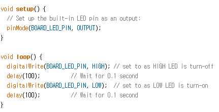
If you change the circuit above to a pull-up circuit as shown below, it will work in the opposite way. If the button is pressed then LOW will be detected, and if it is separated then HIGH will be detected. The reason why HIGH is detected when the button is separated is because there is a 3.3V voltage connected to the pull-up resistor.
Let us receive digital input without either pull-up or pull-down resistors.
In OpenCM9.04 it is possible to configure a switch circuit in digital input without a pull-down or pull-up resistor. The 26 GPIO Pins in OpenCM9.04 have internal input Pull-up/Pull-down resistors that you can configure with the software.
If you need an internal pull-up you can configure as pinMode(7, INPUT_PULLUP) and if you need a pull-down circuit you can configure as pinMode(7, INPUT_PULLDOWN).
If you define as INPUT then it would mean digital input made as floating so there will need to be an exterior pull-up or pull-down circuit. Let us look at an example.
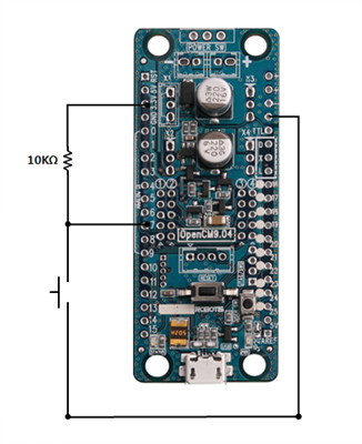
The circuit shown below is a circuit that receives digital input through Pin 7 but the button is directly connected to GND. In this case we can define Pin 7 as INPUT_PULLUP in order for the button to work normally.
In this case if the button in pressed then LOW will be detected, and if the switch is separated then HIGH will be detected due to the internal pull-up.
void setup(){
  pinMode(7, INPUT_PULLUP);
  SerialUSB.begin();
}
void loop(){
  int value = digitalRead(7);
  if ( value == HIGH)
    SerialUSB.println(“HIGH Detected!”);
  else
    SerialUSB.println(“LOW Detected!”);
  delay(100);
}
For the opposite case connect the button directly to the 3.3V as shown in the connectivity below.
In this case if the button is pressed then HIGH will be detected, and if the switch is separated then LOW will be detected due to the internal pull-down.
void setup(){
  pinMode(7, INPUT_PULLDOWN);
  SerialUSB.begin();
}
void loop(){
  int value = digitalRead(7);
  if ( value == HIGH)
    SerialUSB.println(“HIGH Detected!”);
  else
    SerialUSB.println(“LOW Detected!”);
  delay(100);
}
Let us receive an input using the User Button.
Similar to the built-in Status LED, there is a built-in User Button that can be used without the need to make a separate button circuit. If you look at the circuit diagram you can see the built-in pull-down input being used.
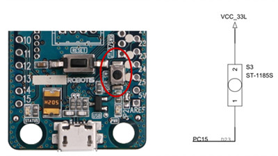
The User Button is connected to Pin 23 so you can designate Pin 23 directly or use BOARD_BUTTON_PIN.
void setup(){
  pinMode(BOARD_BUTTON_PIN, INPUT_PULLDOWN);
  SerialUSB.begin();
}
void loop(){
  int value = digitalRead(BOARD_BUTTON_PIN);
  if ( value == HIGH)
    SerialUSB.println(“HIGH Detected!”);
  else
    SerialUSB.println(“LOW Detected!”);
  delay(100);
}
If you download you will see that when the User Button is pressed then HIGH will be input, and if the switch is separated then LOW will be input due to the internal pull-down circuit.
Let us toggle the Status LED.
If the current output of Pin 1 is HIGH then it will change to LOW, and if it is currently LOW then it will change to HIGH.
digitalWrite(1, HIGH); // Pin 1 which was HIGH will become LOW again.
togglePin(1); // Pin 1 which was HIGH will become LOW again.
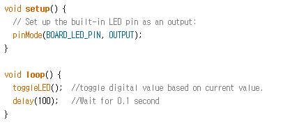
We can now easily write the LED Blink example by using this principle. Let us simply use togglePin() with the Status LED.
void setup(){
  pinMode(BOARD_LED_PIN, OUTPUT); //
}
void loop(){
  togglePin(BOARD_LED_PIN);
  delay(100); //Delay 0.1 second
}
The LED will blink with a 0.1 second interval. Note that using toggleLED() which only toggles BOARD_LED_PIN will achieve the same actions.
Analog I/O
For analog input, it is important to note that only Pins 0~9 located in the OpenCM9.04 silk screen’s ANALOG IN area will support analog input. Analog output is substituted by PWM Output using TIMER.
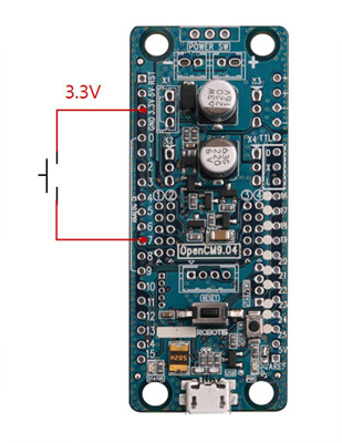
Pin 3 receives analog input by a variable resistor.
Connect a variable resistor to Pin 3 and a voltage of 3.3V as shown below.
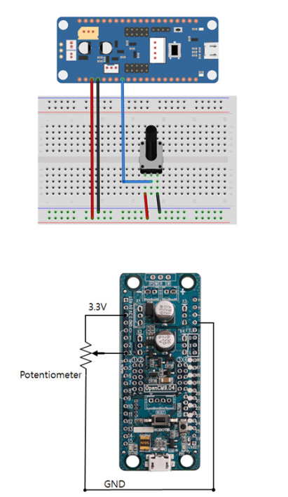
For the analog input in Pin 3, use pinMode(3, INPUT_ANALOG) to configure the Pin Mode as analog input and you are now ready. Use analogRead() to read analog values through Pin 3 as we configured.
int value = analogRead(3); // Reads analog input through Pin 0 and assigns it to the variable value.
Here the value that is assigned to the variable value is a 12bit ADC value between 0 ~ 4,095. Let us output the ADC value that is read through the entire code.
void setup(){
  pinMode(3, INPUT_ANALOG);
}
void loop(){
  int value = analogRead(3);
  SerialUSB.println(value);   // let us output the value.
  delay(100); //delay time for USB transfer
}
Let us perform analog output(PWM) to Pin 6.
We can control the LED using PWM outputted to Pin 6. Connect the LED and resistor using a breadboard and connect to Pin 6 as shown below.
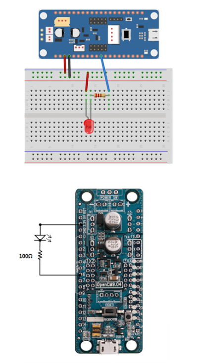
Configure Pin 6 to analog using pinMode(6, PWM). Use analogWrite() to PWM Output to Pin 6 as configured.
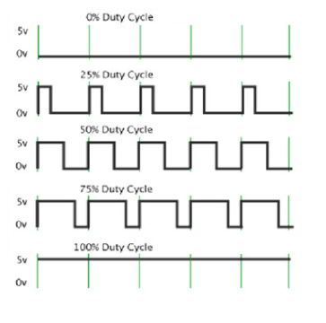
analogWrite(6, 10000);
Analog output is substituted by PWM Output. PWM’s Duty cycle is controlled through the second argument. Here we have used the value 10000 but the duty cycle can be set to a value between 0~ 65535. The value 0 represents a 0% duty cycle and the value 65535 represents a 100% duty cycle.
Now it checks the entire code.
void setup(){
  pinMode(6, PWM);
}
void loop(){
  for(int i=1; i < 7; i++){
    analogWrite(6, i*10000);//generate pwm as 10000 ~ 60000 scale
    delay(100);
  }
}
By controlling the second argument of analogWrite() we can implement PWM with a variety of Duty Cycles as shown below.
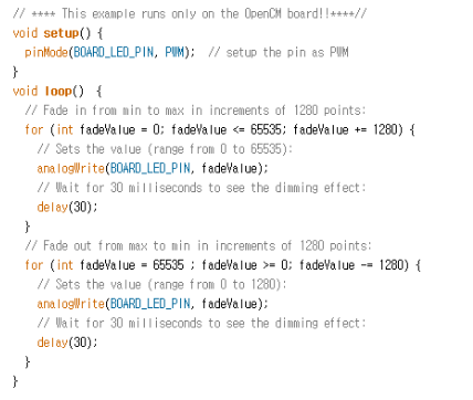
Let us perform Dimming so that the Status LED will turn off slowly.
The Status LED is connected to Pin 14 which is also capable of PWM output. Open an example file by selecting File –> Examples –> 01. Basics –> f_Led_Fadin.
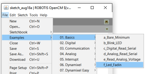
If you download to OpenCM9.04 it will make the Status LED repeatedly turn on and off slowly.
Serial Communication
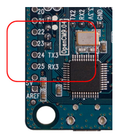
OpenCM9.04 has a total of 4 serial devices. There are Serial1, Serial2, Serial3, and SerialUSB, but Serial1 is assigned exclusively as DYNAMIXEL communication port so there are restrictions for using it. Serial 2 is for using Bluetooth devices with 4 pin ports such as BT-210 and BT-110A. Serial3 is shown at the back-side of the PCB as TX3(24), RX3(25).
The SerialUSB is very important in OpenCM9.04. It performs the firmware download for ROBOTIS OpenCM and also performs data communication as do Serials 1,2,3. The instructions to use it is almost the same as for Serials 1,2,3.
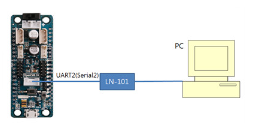
Let us send data using a serial device.
Using LN-101 connect the 4 pin communication port to the PC as shown below. Use RoboPlus Terminal or a serial monitor in the PC to open the COM port.
You must perform an initialization for the Serial 2 device as shown below and then perform the following examples in loop().
void setup(){
  Serial2.begin(57600);
}
void loop(){
  //Test example code
}
Sending data can be done using print() and println() methods, where the print() method will print without changing lines and the println() method will print as well as change lines.
Serial2.print(“Hello World This is OpenCM9.04”);
Let us print the “Hello World” string through the Serial2(TX2, RX2) device.
Serial2.print(“OpenCM9.04 is the first product of OpenCM Series”);
Serial2.println(“ println() ends this line”);
Seirla2.println(“This is new line”);
println() will change lines and print as a new line. You can check the printing as shown below.

Serial2.print(12);
This will print 12 as a decimal number.
int abc = 128;
Seial2.print(abc);
This will print the value 128 of variable abc.
Serial2.print(abc, 16);
This will print the value 128 of variable abc as a hexadecimal value. 0x80 will be printed.
Serial2.print(abc, 2);
This will print the value 128 of variable abc as a binary value. In the same way, if you set the second argument as 8 then it will print as an octal value, and if there is no second argument then by default it will print as a decimal value.
Serial2.println(3.14);
This will print 3.14 as a Double type and then change lines. It will print to 2 decimal places. You can also define a variable Double and then print it.
double  var = 1.234;
Serial2.println(var);
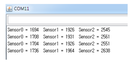
This will print the analog values read from Pin 0, 1, and 2 through Serial 2 in their respective order. If you use many print() and println() methods then you can print neatly as shown below.
int sensorValue0=0;
int sensorValue1=0;
int sensorValue2=0;
sensorValue0 = analogRead(0);
sensorValue1 = analogRead(1);
sensorValue2 = analogRead(2);
Serial2.print(“Sensor0 = “); Serial2.print(sensorValue0);
Serial2.print(“ Sensor1 = “); Serial2.print(sensorValue1);
Serial2.print(“ Sensor2 = “); Serial2.println(sensorValue2);
At last If you change lines by using the println() method only for printing sensorValue2 then you can achieve a neat printing of the 3 analog inputs.
Let us receive data using a serial device.
We will implement an Echo function using a serial device. When data comes to the Serial 2 device through a char-type variable temp then we will save the data using the read() method and print right away using the print() method to implement the Echo function.
char temp = 0;
loop(){
  if ( Serial2.available() ){
    temp = Serial2.read();
    Serial2.print(temp);
  }
}
The entire code is shown below.
void setup(){
  Serial2.begin(57600);
}
byte temp = 0;
void loop(){
  if ( Serial2.available() ){
    temp = Serial2.read();
    Serial2.print(temp);
  }
}
Let us implement it in an interrupt driven method as shown below. The interrupt of a Serial device is configured as a function that does not have a return type and contains one byte-type argument. And here if we print the data given by the print() method right away then we have implemented the Echo function. You can implement and use in any location without separately defining a prototype.
void serialInterrupt(byte buffer){
  Serial2.print(buffer);
}
Inside setup() we can configure the implemented serialInterrupt() as a function pointer format using attachInterrupt().
Serial2.attachInterrupt(serialInterrupt);
The entire code for inputting data of Serial 2 using the interrupt is shown below.
void setup(){
  Serial2.begin(57600);
  Serial2.attachInterrupt(serialInterrupt);
}
void serialInterrupt(byte buffer){
  Serial2.print(buffer);
}
void loop(){
  //Code is not necessary.
}
Let us print data using the SerialUSB device.
Use the Micro-B USB connector of OpenCM9.04 to connect directly to the PC as shown below. In this example we communicate with the PC only using OpenCM9.04 without any device such as LN-101.

You must perform an initialization for the SerialUSB device as shown below and then perform the following examples in loop(). There is no designation of Baud rate.
void setup(){
  SerialUSB.begin();
}
void loop(){
  //Test example code
}
The instructions to use it is almost the same as for the Serial devices. You can control it in the same way by using print() and println() methods.
SerialUSB.print(“CM-900 is the first product of CM-9 Series”);
SerialUSB.println(“ println() ends this line”);
SeirlaUSB.println(“This is new line”);
``

This will print 12 as a decimal number.

```c
SerialUSB.print(12);
This will print through an int-type variable.
int abc = 128;
SerialUSB.print(abc);
This time we will print the value of variable abc as a hexadecimal value.
SerialUSB.print(abc, 16);
This will print the value 128 of variable abc as a hexadecimal value, which is 0x80.
SerialUSB.print(abc, 2);
This will print the value 128 of variable abc as a binary value. In the same way, if you set the second argument as 8 then it will print as an octal value, and if there is no second argument then by default it will print as a decimal value.
SerialUSB.println(3.14);
This will print 3.14 as a Double type and then change lines. It will print to 2 decimal places. You can also define a variable Double and then print it.
double  var = 1.234;
SerialUSB.println(var);
Let us receive data using the Serial USB device.
We will implement an Echo function using the Serial USB device. When data comes to the Serial USB device through a char-type variable temp then we will save the data using the read() method and print right away using the print() method to implement the Echo function.
char temp = 0;
loop(){
  if ( SerialUSB.available() ){
    temp = SerialUSB.read();
    SerialUSB.print(temp);
  }
}
The entire code is shown below.
void setup(){
  SerialUSB.begin();
}
byte temp = 0;
void loop(){
  if ( SerialUSB.available() ){
    temp = SerialUSB.read();
    SerialUSB.print(temp);
  }
}
Let us implement it in an interrupt driven method as shown below. The interrupt of the Serial USB device is configured as a function that does not have a return type and contains a byte-type argument and a byte* argument. And here if we print the data given by the print() method right away then we have implemented the Echo function. If you write data to the USB COM Port through the PC’s terminal it will send 1 byte at a time so it is sufficient to set nCount =1 and Echo only the Index 0 data of the buffer.
void usbInterrupt(byte nCount, byte* buffer){
  SerialUSB.print(buffer[0]);
}
Inside setup() we can configure the implemented usbInterrupt() as a function pointer format using attachInterrupt()
SerialUSB.attachInterrupt(usbInterrupt);
We can leave the loop() function as an empty function as shown below.
void loop(){
}
The entire code for using the Interrupt of the SerialUSB device is shown below.
void setup(){
  SerialUSB.begin();
  SerialUSB.attachInterrupt(usbInterrupt);
}
void usbInterrupt (byte nCount, byte* buffer){
  SerialUSB.print(buffer[0]);
}
void loop(){
  //Code is not necessary.
}
External Interrupt
Let us write a code that turns the LED off and on when the signal input to Pin 7 changes. Connect the switch connected to the 3.3V to Pin 7 as shown below. We will use the internal input pull-down option without using the external pull-down circuit. In the same way connect the LED and resistor to the 3.3V and then connect it to Pin 13. Be cautious of the direction of the LED.
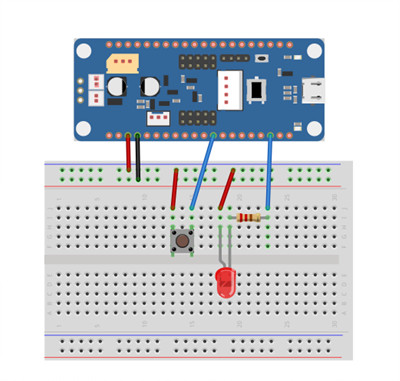
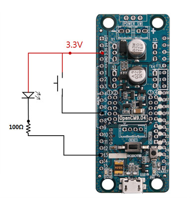
Let us use a global variable to make a flag and apply the method of toggling the flag in the interrupt routine whenever the signal from Pin 7 changes.
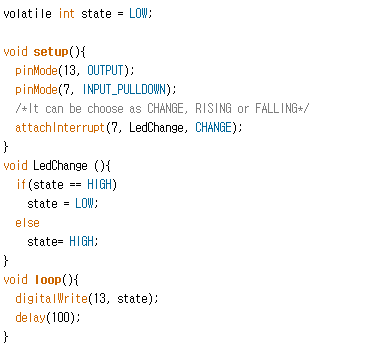
volatile int state = LOW;
In setup() we will configure the external interrupt with the attachInterrupt() function and define the related Pin 7 as INPUT_PULLDOWN in pinMode.
pinMode(7, INPUT_PULLDOWN);
attachInterrupt(7, LedChange, CHANGE);
We will implement LedChange () as a void LedChange (void) type.
void LedChange (){
  if(state == HIGH)
  state = LOW;
  else
  state= HIGH;
}
loop(){
  digitalWrite(BOARD_LED_PIN, state);
}
The entire code is shown below.
DYNAMIXEL Instructions
DYNAMIXEL used in the example below will be under the premise that ID=1 and the communication speed have all been initialized to 1Mbps. Even though DYNAMIXEL class has not been defined explicitly, we will assume that is has been predefined as shown below.
Dynamixel Dxl(1); // Dynamixel Bus on Serial1(USART1)
Let us read the model number and firmware version of AX-12A.
In the E-manual the address value of the model number and firmware version in the Control Table is shown below.
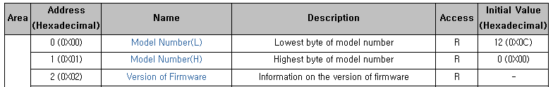
In AX-12A, for which the ID number is 1, we will read from address number 0 which corresponds to the model number’s low-order byte and from address number 2 which corresponds to the firmware version information. They are all 1 byte so we can use a byte-type variable.
byte nModel = Dxl.readByte(1, 0); // First we read the model number
byte vFirmware = Dxl.readByte(1, 2); // Then we read the firmware version.
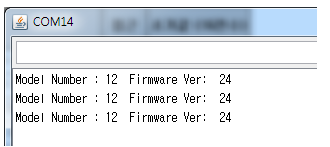
We will print as below.
SerialUSB.print(“Model Number : “);SerialUSB.print(nModel);
SerialUSB.print(“ Firmware Ver : “);SerialUSB.println(vFirmware);
We will read the internal temperature of AX-12A, for which the ID number is 1.
The address value that corresponds to the internal temperature of AX-12A in the Control Table is shown below.

Using the same method we will read one byte using readByte().
byte temp = Dxl.readByte(1, 43);
SerialUSB.print(“Current Temperature : “);
SerialUSB.println(temp);
Let us configure the ID as 2 for AX-12.
We will record 1 byte in the address number 3, which corresponds to DYNAMIXEL ID, using the method writeByte().

void setup(){
  Dxl.begin(1);
  delay(1000);  // It is good to give about 1 second of delay.
  Dxl.writeByte(1, 3, 2); //Changes the ID number 1 of DYNAMIXEL to ID number 2
}
void loop(){
  Dxl.writeByte(2, 25, 1);  //LED Blinking using the changed ID number
  delay(100);
  Dxl.writeByte(2, 25, 0);
  delay(100);
}
If the change in ID number successfully finishes DYNAMIXEL’s LED will blink.
Let us change the Baud Rate to 57600 bps.
The communication speed of DYNAMIXEL can be changed by using the Baud rate in address number 4. Similar to change the ID number we will use the writByte() method. If we utilize DYNAMIXEL speed computation of 57,600bps then the index value comes out as 34. For DYNAMIXEL 2.0 protocol please refer to the new Baud rate table - for 57600bps the index value will be 1.

void setup(){
  Dxl.begin(1);
  delay(1000);  // It is good to give about 1 second of delay.
  Dxl.writeByte(1, 4, 34); // 34 = 57600 bps
  Dxl.begin(34); // Initializes to the changed Baud rate
  delay(1000);
}
void loop(){
  Dxl.writeByte(1, 25, 1);
  delay(100);
  Dxl.writeByte(1, 25, 0);
  delay(100);
}
Since the Baud rate has been modified we need to initialize the Bus again to Dxl.begin(34).
Let us check whether DYNAMIXEL for which ID number is 1 has moved or not.
We can check the current movement status of AX-12A by using the value 46(0x2E) in the Control Table.

byte bMoving = Dxl.readByte(1, 46);
If DYNAMIXEL with ID number 1 is currently moving then the value 1 will be returned for the variable bMoving, and if it is not moving then the value 0 will be returned.
Let us move the AX-12A DYNAMIXEL to a location of 150 degrees.
To move DYNAMIXEL to the desired location (150 degrees) we need to input the desired location to the address that corresponds to the Goal Position. It is composed of 2 bytes (a low-order byte and a high-order byte) as shown below, and instead of accesses them individually we recommend recording 2 bytes (1 word) to the low-order byte 30(0x1E) using writeWord().

In the E-manual we can check that the location that corresponds to 150 degrees it matched to 512 as shown below.

Dxl.writeWord(1, 30, 512);
Now check if the communication was successful using the function Dxl.getResult().
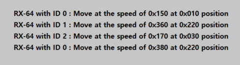
For each RX-64 let us move them each to the following locations and speeds.
After we finish moving them we will return them all to their original location of 0. This action will be repeated continuously.
Let us create a Sync Write packet data that we will send to each DYNAMIXEL. We will create a Sync Write packet data for the 0 location and another packet data to save the goal position and speed.
#define PACKET_LEN 12
#define NUM_OF_DATA 2
int SyncPage1[PACKET_LEN]=
{  1, 010, 150,
  2, 220, 360,
  3, 020, 170
  4, 220, 380};
int SyncPage2[PACKET_LEN]=
{  1, 0, 0,
  2, 0, 0,
  3, 0, 0
  4, 0, 0};
void loop(){
  Dxl.syncWrite(30, NUM_OF_DATA, SyncPage1, PACKET_LEN);
  delay(1000);
  Dxl.syncWrite(30, NUM_OF_DATA, SyncPage2, PACKET_LEN);
  delay(1000);
}
Let us restrict the movement angle to 0~150 degrees.
If the CCW Angle Limit is 0x3FF then it is 300 degrees, so we will send 0x200 which corresponds to 150 degrees using the writeByte() method.
CAUTION : If you set the CCW Angle Limit in number 8 to 0 then it will change to wheel mode and you will not be able to control the Goal position.

Dxl.writeWord(1, 8, 0x200);
if( Dxl.getResult() == COMM_RXSUCCESS ){ // Check if the communication was successful...}
Let us configure the movement voltage to 10V ~ 17V.
The data for 10V is 100(0x64), and the data for 17V is 170(0xAA), so we use the writeByte() method for each of them to record the lower and upper limits. The Control Table addresses for them are lower-range voltage= 12(0x0C) and upper-range voltage = 13(0x0D) respectively.

Dxl.writeByte(1, 12, 100);
Dxl.writeByte(1, 13, 170);
if( Dxl.getResult() == COMM_RXSUCCESS ){ // Check if the communication was successful...}
Let us limit the torque to only 50% of its maximum value.
We will configure the MAX Torque value from its maximum value 0x3FF to 50% which is 0x1FF. We will write the data to the Max Torque’s lower-order byte address 14(0x0E) using writeByte().

Dxl.writeByte(1, 14, 0x1FF);
if( Dxl.getResult() == COMM_RXSUCCESS ){ // Check if the communication was successful...}
You need to turn the power off and then restart the power for the Max Torque to change.
Let us move to the Position of 180 degrees with speed 57RPM.
Moving Speed( Address 32(0x20) ) = 512(0x200)
Goal Position( Address 30(0x1E) ) = 512 (0x200). We will access data by units of words as shown below.
Dxl.writeWord(1, 32, 512);  // Configure the speed as 57 RPM
Dxl.writeWord(1, 30, 512);   // Move to location 180 degrees
if( Dxl.getResult() == COMM_RXSUCCESS ){ // Check if the communication was successful...}
Move ID #0 AX-12 to 0°, and move ID #1 AX-12 to 300°
We will start with both AX-12 in the same position. Similar to Syncwrite, we will create a Packets directly using the setTxPacketXXX() method. In this case we will make a Packet using INST_REG_WRITE and INST_ACTION. Note that the location of 1 degrees corresponds to 0, and the location of 300 degrees corresponds to 1023(0x3FF).
ID=0, Instruction = INST_REG_WRITE, Address = 30(0x1E), Data = 0
ID=1, Instruction = INST_REG_WRITE, Address = 30(0x1E), Data = 1023
Dxl.setTxPacketId(0); // We specify the control of ID number 0.
Dxl.setTxPacketInstruction(INST_REG_WRITE);
Dxl.setTxPacketParameter(0, 30); // Goal Position Address
Dxl.setTxPacketParameter(1, Dxl.getLowByte(0)); // Low Byte
Dxl.setTxPacketParameter(2, Dxl.getHighByte(0)); // High Byte
Dxl.setTxPacketLength(5);  //Total data length = Data length + 3
Dxl.txrxPacket();
if( Dxl.getResult() == COMM_RXSUCCESS ){ // Check if the communication was successful...}

Sending packet for the second DYNAMIXEL
Dxl.setTxPacketId(1);
Dxl.setTxPacketInstruction(INST_REG_WRITE);
Dxl.setTxPacketParameter(0, 30); // Goal Position Address
Dxl.setTxPacketParameter(1,Dxl.getLowByte(1023)); //Low Byte
Dxl.setTxPacketParameter(2, Dxl.getHighByte(1023)); //High Byte
Dxl.setPacketLength(5);
Dxl.txrxPacket();
if( Dxl.getResult() == COMM_RXSUCCESS ){ // Check if the communication was successful...}

To execute the Instruction that was on standby in the registers of DYNAMIXEL number 0 and 1, send the Packet INST_ACTION.
Dxl.setTxPacketId(BROADCAST_ID);
Dxl.setTxPacketInstruction(INST_ACTION);
Dxl.setTxPacketLength(2);
Dxl.txrxPacket();
if( Dxl.getResult() == COMM_RXSUCCESS ){ // Check if the communication was successful...}

We recommend checking if the communications was successful after creating and sending each Packet.
RC-100
How to connect OpenCM9.04 using RC100 by using OpenCM’s RC100 library we can control OpenCM9.04 remotely. Below you can see the various wireless connections that you can make between OpenCM9.04 and RC100. The RC100 library will only work normally if a communication model is connected to the 4 pin communication port of OpenCM9.04. Please refer to the RC-100 for information on the RC-100 communication packet.
Bluetooth connection using RC-100B + BT-100 or BT-210
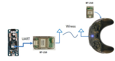
Connecting to the RC100 controller using Bluetooth
ZigBee connection using RC-100B + ZIG-100/ZIG-110A
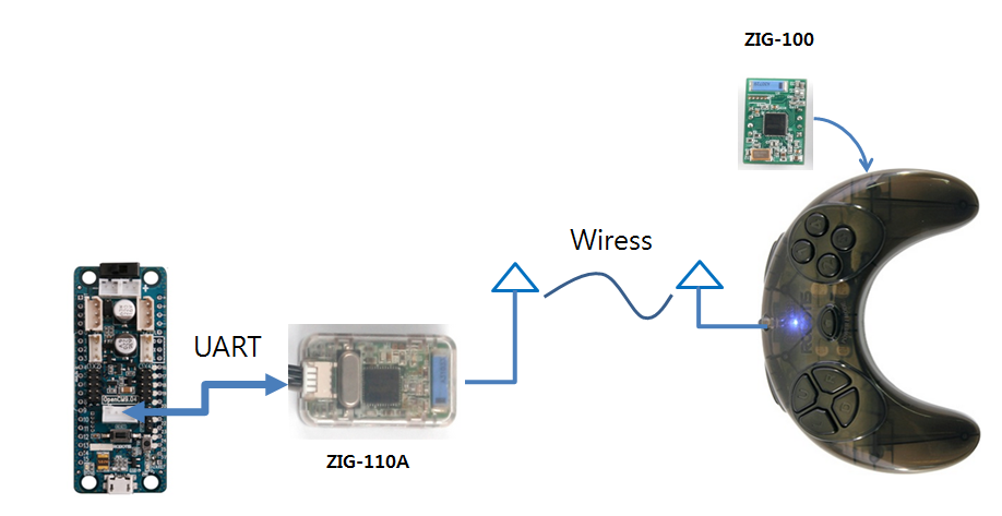
Connecting OpenCM9.04 and the RC100 controller using ZigBee
Infrared connection using RC-100B + IR Receiver OIR-10
Please refer to IR-10 for information on infrared communication methods for RC-100A or RC-100B.
Bluetooth connection using an Android smartphone + BT-210
For Android smartphones you can use the R+ m.Task application’s RC100 simulation to send RC-100 packets. You can download R+m.Task through Google Play.
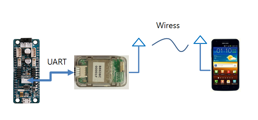
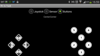
Connecting OpenCM9.04 and your smartphone using Bluetooth – using the RC100 feature of R+m.Task
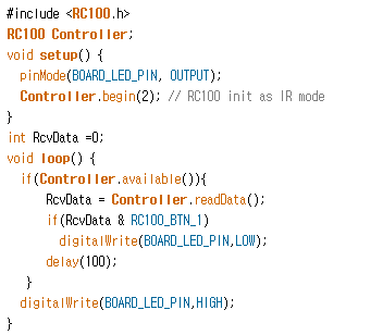
Let us make the Status LED of OpenCM9.04 blink when Button 1 of RC100 is pressed.
The RC100 library is used to process the RC100 packets in OpenCM9.04.
The RC100 library can be started in 2 modes, the wireless communication mode and the infrared communication mode.
- Wireless communication mode(1) : Bluetooth module(BT-210/BT-110A), ZigBee module(ZIG-110A)
- Infrared communication mode(2) : Infrared receiver(OIR-10)
We will initialize to the RC100 library using the wireless communication mode.
#include <RC100.h>
RC100 Controller;
Controller.begin(1);  //RC100 init as remote mode
Please refer below for defining each button of RC100.
#define RC100_BTN_U (1)
#define RC100_BTN_D (2)
#define RC100_BTN_L (4)
#define RC100_BTN_R (8)
#define RC100_BTN_1 (16)
#define RC100_BTN_2 (32)
#define RC100_BTN_3 (64)
#define RC100_BTN_4 (128)
#define RC100_BTN_5 (256)
#define RC100_BTN_6 (512)
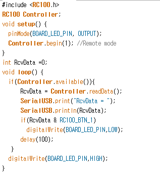
If the packet data read using the RC100 library is Button 1 then output the Status LED to LOW.
if(Controller.available()){
  RcvData = Controller.readData()
  if(RcvData & RC100_BTN_1)
    digitalWrite(BOARD_LED_PIN, LOW);
}
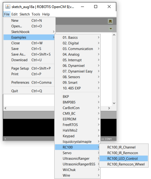
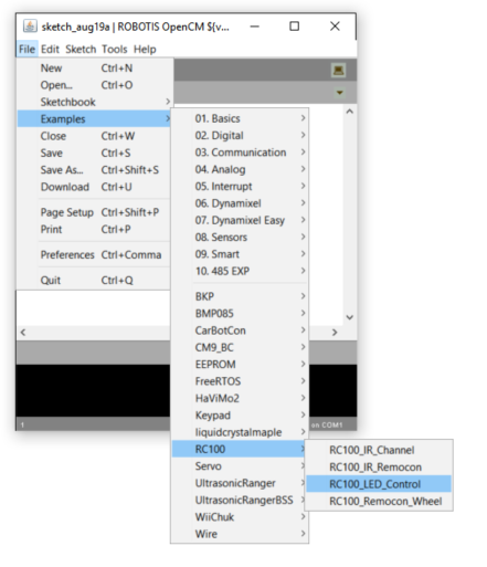
The entire code is shown below, and you can open the same code by selecting File -> Examples -> RC100 -> RC100_LED_Control.
In the same way, we will make the Status LED blink using the OIR-10 Infrared receiver.
We will initialize the Infrared communication mode to the number 2 as shown below.
#include <RC100.h>
RC100 Controller;
Controller.begin(2);  //RC100 init as IR mode
The remaining actions are the same as the previous example.
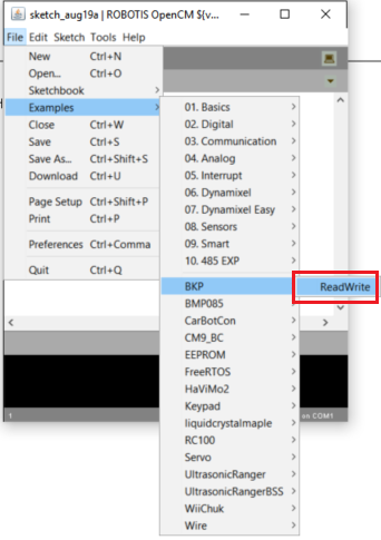
BKP Library
The BKP Memory always preserves the data as long as the power is kept on so it is useful for temporarily saving user data or important data and then, after returning from reset, accessing the data again. The OpenCM board provides API for the BKP Memory as an external library. Select File -> Examples -> BKP -> ReadWrite as shown below.
Once you select the examples the following codes appear.
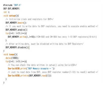
Example Explanation
In setup() we initialize the BKP Memory and initialize the Serial2 device to 57,600bps. Then print “Start OpenCM9.04 BKP Memory Test” through Serial2 and start loop().
STM32F103CB of OpenCM is composed of a BKP Memory with a total of ten 16bit registers.
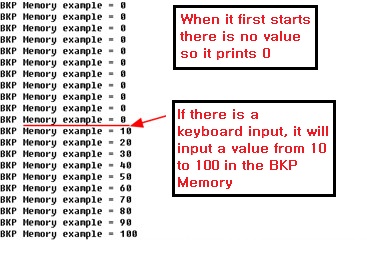
In loop() we will output data from addresses 1 to 10 with a 1 second interval, and when
#include "BKP.h"
BKP BKP_MEMORY;
int i;
void setup(){
  /* Initialize clock and registers for BKP*/
  BKP_MEMORY.begin();
  Serial2.begin(57600);
  Serial2.println("Start OpenCM9.04 BKP Memory Test");
}
void loop(){
 delay(1000);
 for(i=1; i<11;i++){
   Serial2.print("BKP Memory Read = ");
   Serial2.println(BKP_MEMORY.read(i));
 }
 if(Serial2.available()){
   BKP_MEMORY.enable();
   for(i=1; i<11;i++){
     BKP_MEMORY.write(i,i*10);
   }
   BKP_MEMORY.disable();
 }
}
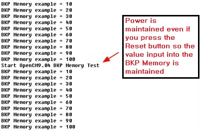
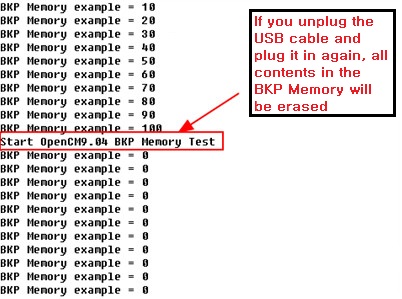
An important property of the BKP Memory is that even if you press Reset and the CPU restarts, the BKP Memory values will remain the same. However if you unplug the power and then plug in the power again the data will disappear. Below you can check the property of the BKP Memory using the output value.