Introduction
RoboPlus Manager 2.0
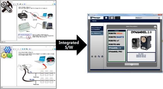
The RoboPlus Manager 2.0 manages the Controller and DYNAMIXEL devices that comprise the robot. By connecting the product, the user can update the product to the latest version and test the Control Table. The functions that were previously provided in RoboPlus Manager 1.0 and Wizard 1.0 have been combined in RoboPlus Manager 2.0.
Precautions
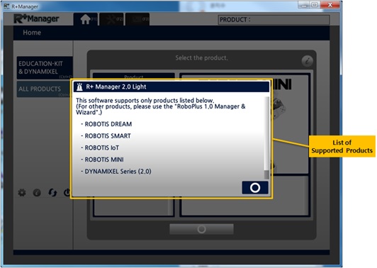
Supported products are limited starting from V2.0.0. For products that are not included in the list of supported products, please use RoboPlus Manager 1.0 and Wizard 1.0.
List of Supported Products
- Robotis Dream
- Robotis MINI
- DYNAMIXEL 2.0 Series (MX-28, MX-64, MX-106, XL-320, XM Series, XH Series, Pro Series)
Definition of Firmware
Firmware is basic software that is installed on a device to operate the hardware. Firmware contains communication protocols with PC, smartphone, and other devices so it is recommended to keep the firmware to the latest version.
All devices (Controller, DYNAMIXEL etc) have firmware installed when first purchased, but new versions can be released if there are additional functions / bug fixes.
Role of Controller Firmware
- Operates the control program written using RoboPlus Task
- Interprets the motion data written using RoboPlus Motion
- Performs packet communication function with PC, smartphone, and DYNAMIXEL
Role of DYNAMIXEL Firmware
- Performs packet communication function with Controller when operating control program or motion on the Controller
- Performs packet communication function with PC, smartphone, and DYNAMIXEL
Importance of Firmware Update
- A new firmware can be released if there are additional functions or modifications to previous functions.
- A new firmware can be released to improve compatibility if supporting a new S/W is necessary.
- A new firmware can be released if there is a bug fix.
- If the product does not function properly or communication is unstable, updating to the latest firmware may fix the problem.
Menu Description
Editing Tab for Each Stage
The workspace is divided into Home Tab, Managing Tab, and Terminal Tab. (The Self-Checklist / Calibration functions in the Managing Tab and the Terminal Tab are not available as of yet in V2.0.0.)
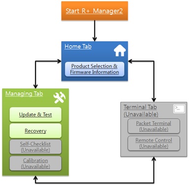
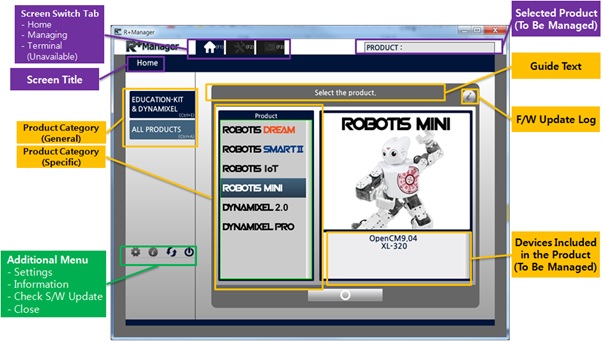
Home Tab
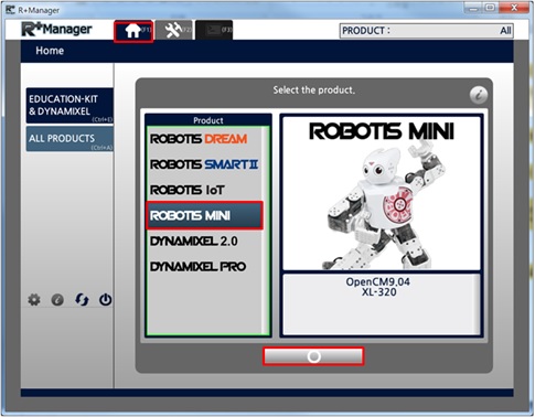
This is the first screen right after starting the program, which provides functions such as Product Selection menu and Firmware Update history function, etc
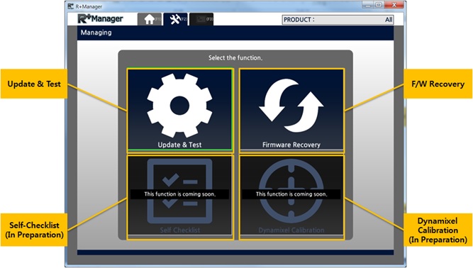
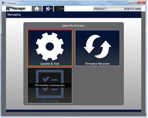
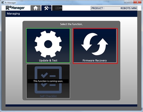
Management Tab
This tab provides Firmware Update / Test / Recovery functions for the previously selected product. Depending on the selected product, the functions that can be used are filtered and showed.
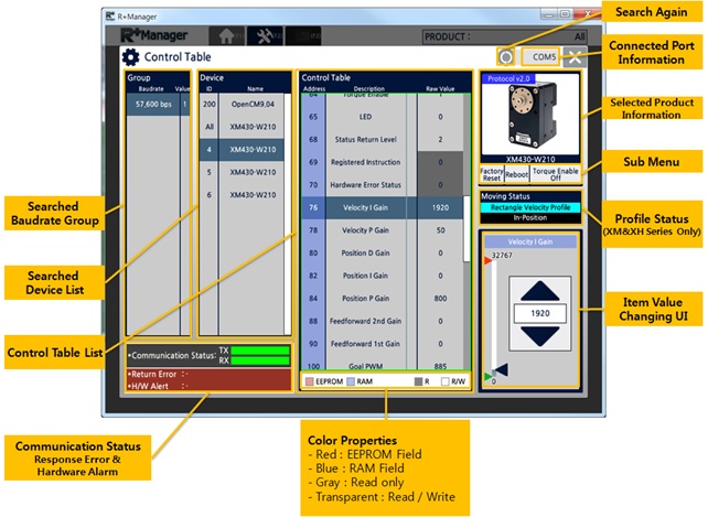
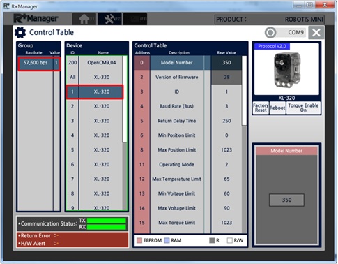
The figure below is a screen of testing the Control Table. It shows all searched products according to their communication speed and device model, and you can test by modifying the values in the Control Table.
Terminal Tab
This feature is currently being prepared and will be supported in upcoming updates.
Basic Features
Firmware Update
-
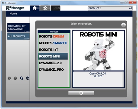
In the Home Tab,select the product that you wish to update or test. (ROBOTIS MINI was selected in the example below)
-
Select the “Update & Test” menu.
-
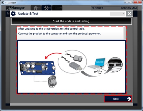
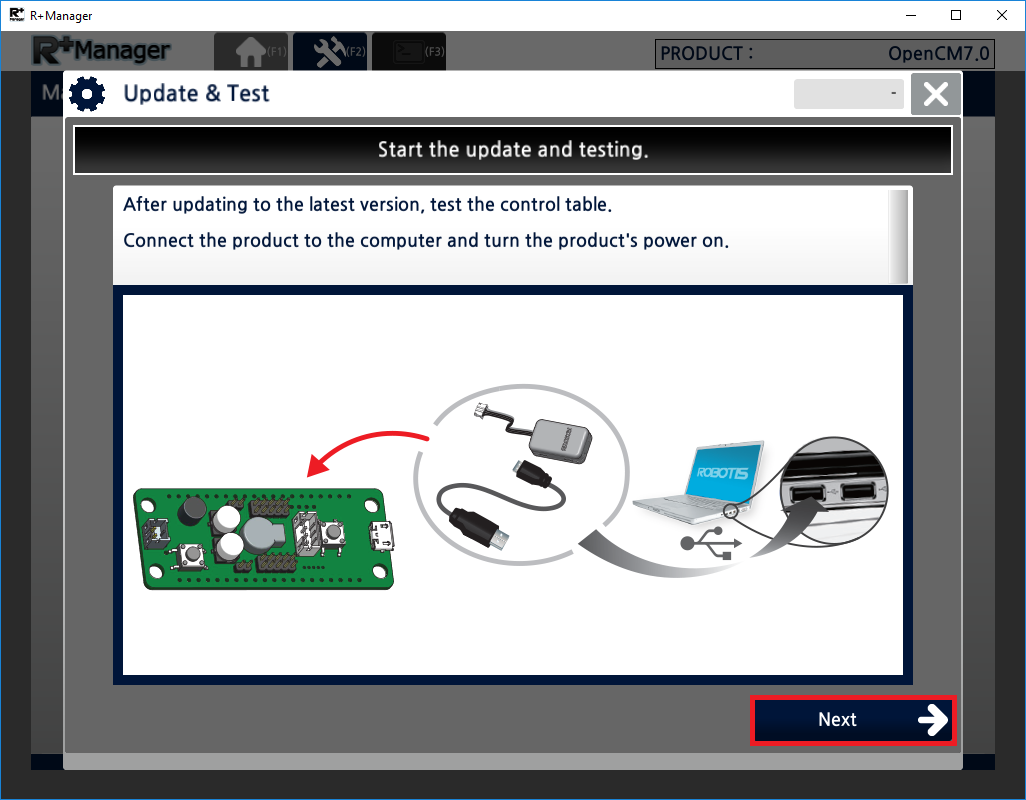
Connect the product with the PC as guided on screen and then turn on the product.
-
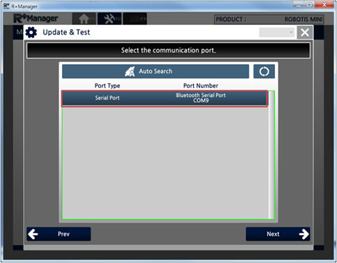
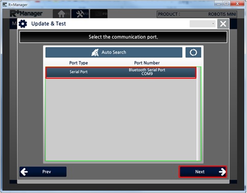
Select the connection port and click the “Next” button. (Bluetooth serial port was used in the example below)
-
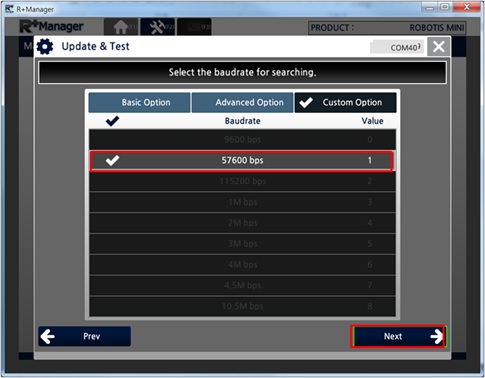
Select the communication speed to search and click the “Next” button. (When using Bluetooth serial port, only 57,600bps can be used)
-
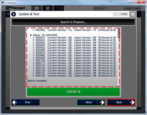
Check if the device to be managed has been properly searched and click the “Next” button. (If the product is not searched properly, then click the “Try Again” button.)
-
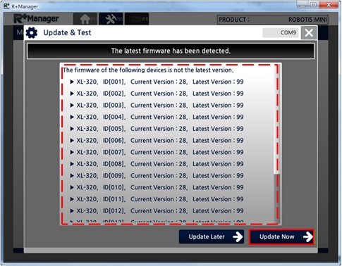
If the content to be updated is detected, then the “Update Now” button below will be activated. Check the update content and click the “Update Now” button.
-
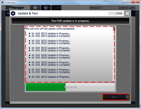
Wait until the update has been properly completed and click the “Next” button.
-
If the update has been completed, then the “Control Table test” function will be executed. (Some controllers will turn off after the update is complete, and the window will be closed.)
Firmware Recovery
-
In the Home Tab, select the product that you wish to recover. (ROBOTIS MINI was selected in the example below)
-
Select the “Firmware Recovery” menu.
-
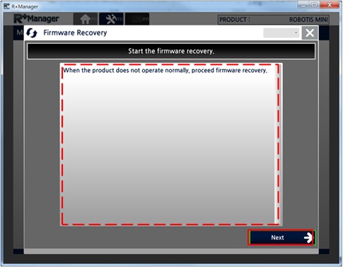
Check the notification message and click the “Next” button.
-
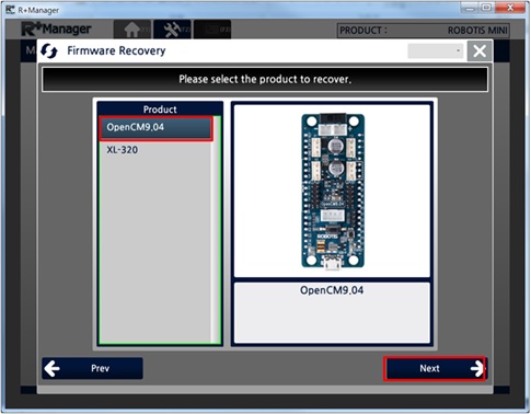
Select the product you wish to recover and click the “Next” button. (OpenCM9.04 was selected in the example below)
-
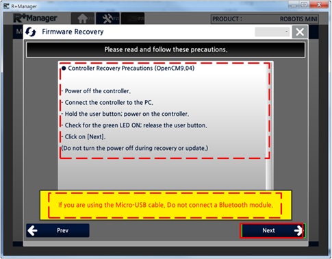
Follow the instructions that appear in order. Be sure to the check the yellow warning message below.
-
After all preparations are finished click the “Next” button.
-
Select the connection port and click the “Next” button. (Bluetooth serial port was used in the example below)
-
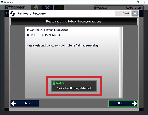
Once the device is connected, bootloader is detected for firmware installation. Click the “Next” button when it is activated.
-
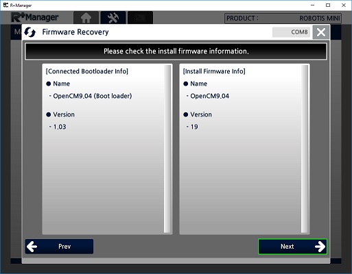
Check the information of the firmware to the installed and click the “Next” button.
-
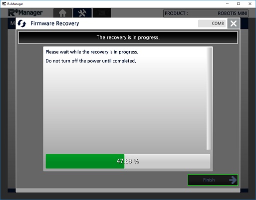
When the recovery is complete, click the “Finish” button.
DYNAMIXEL Control Table
-
To begin we will assume the Control Table window is open. (Please refer to the Firmware Update section for the connection process.)
-
The Control Table window categorizes the control tables according to their communication speed and device model. Select the communication speed and device model that you wish to test. (XL-320 was selected in the example below.)
-
From the menu on the right, clicking the “Factory Reset” button will restore all settings of the product to their factory default configuration.
(The ID and Baud Rate value will not be changed.)
From the menu on the right, clicking the “Rebooting” button will restart the corresponding DYNAMIXEL.
From the menu on the right, click the “Turn On/Off Torque” button will turn the corresponding DYNAMIXEL torque on or off.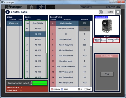
-
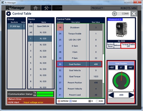
From the menu on the right, click the “Turn On Torque” button to turn DYNAMIXEL torque on.
-
In the Control Table list, search and select the “Goal Position” item.
-
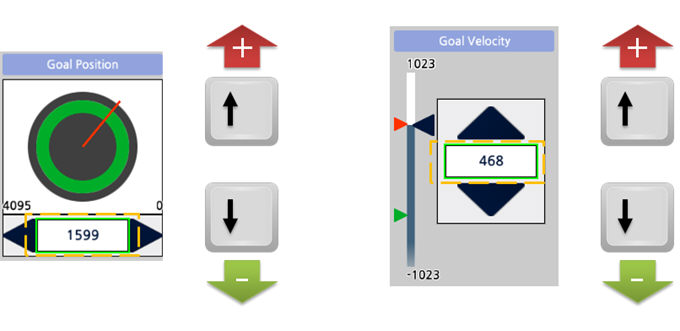
Use the Goal Position control on the lower right corner to move the motor.
WARNING : Take caution since the motor can suddenly move in the process of changing the value.
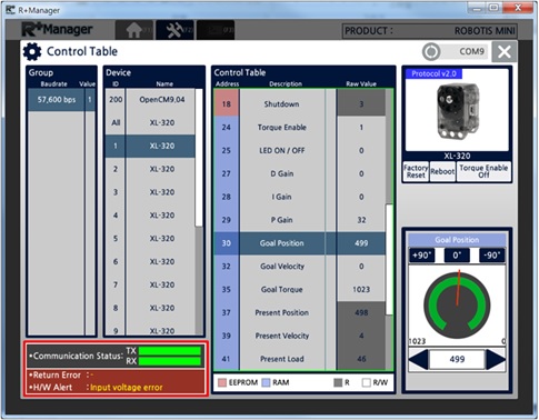
- You can check if the current communication between the PC and the product is normal through the “Communication Status” LED on the lower left corner. (Green : Normal, Yellow : Time-Out, Red : Data Loss)
- You can check DYNAMIXEL response status through the “Response Error” message on the lower left corner.
-
You can check the hardware’s error status through the “Hardware Alarm” message on the lower left corner.
-
Some DYNAMIXEL’s provide the function to view the Profile Type status.
In a given Operating Mode, the Profile Type is decided by the Profile Acceleration value and the Profile Velocity value. Please refer to the corresponding DYNAMIXEL E-Manual for details. (Supported products : XM Series and XH Series)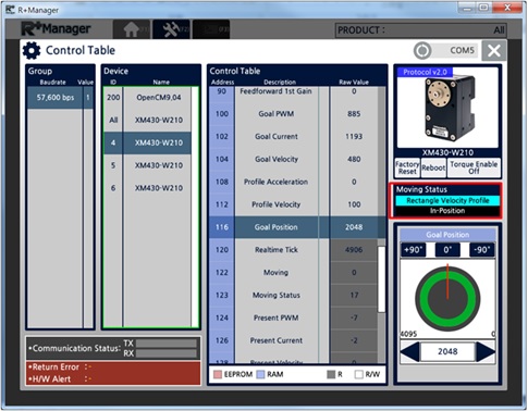
NOTE : For further information about the Control Table, please refer to each DYNAMIXEL.
Controller Control Table
-
Select the controller to connect in the
Hometab. (OpenCM7.0 is selected in the example)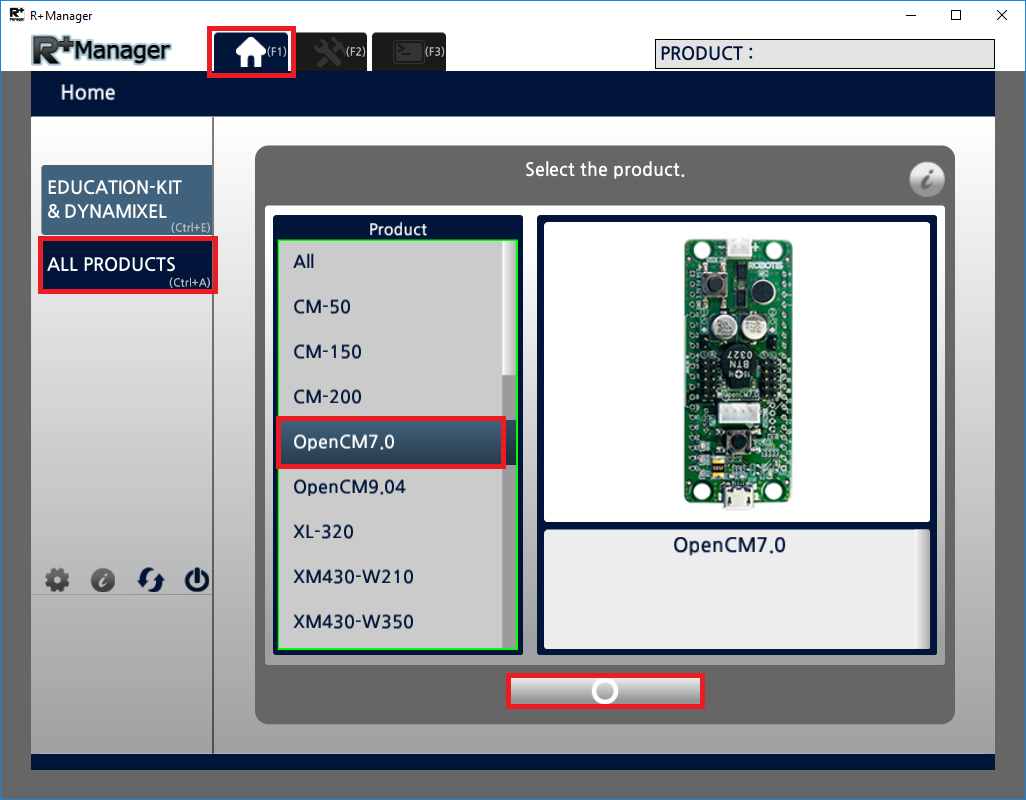
-
Click
Update & Testicon.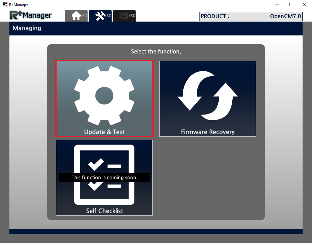
-
Connect the controller to PC according to the described image.
-
Select COM port to establish connection between PC and controller.(USB port is selected in the example)
ClickNextbutton.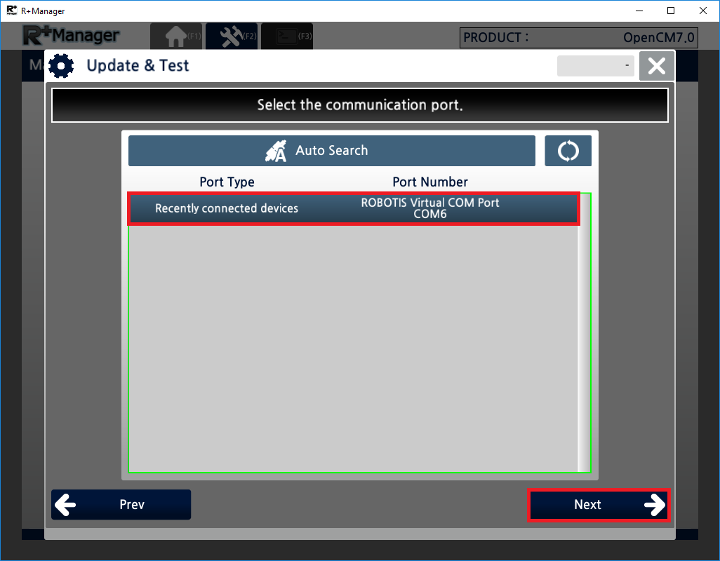
-
Select Baud Rate to establish connection between PC and controller. Click
Nextbutton.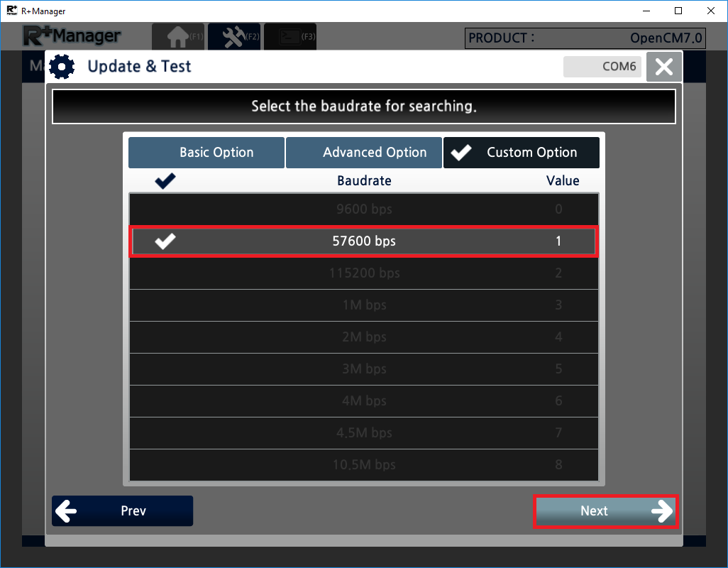
-
Confirm detected device with selected port and baudrate then click
Nextbutton. If the device is not detected, clickRetrybutton and try again.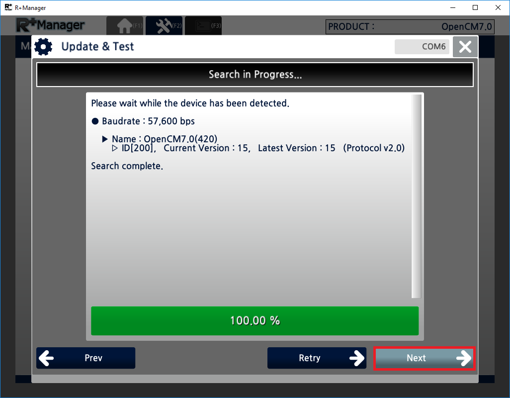
-
If there is any available firmware updates for the device, update menu will be available. Click
Update Nowbutton to update the device.
If connected device already has the latest firmware, you will see below screen.
ClickNextbutton to proceed.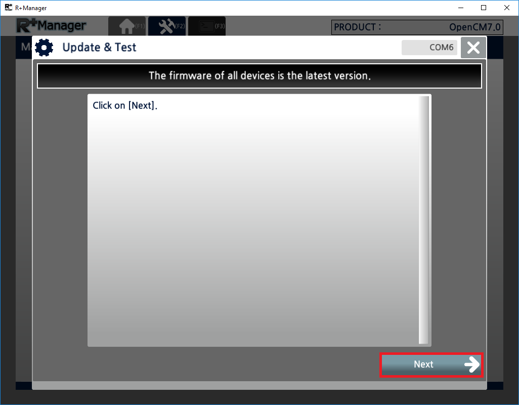
-
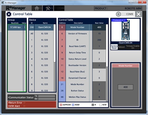
When the connection is established between PC and controller, below screen will be appeared. Control Table window arranges device with Baudrate and Device. If you have connected multiple devices, select baudrate and device of the controller to test.
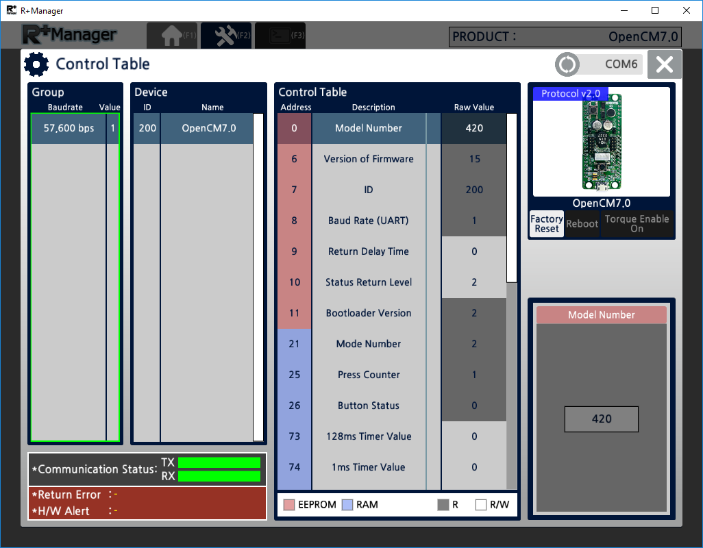
-
On the right column of the window,
Factory Resetbutton will reset all configuration except ID and Baudrate.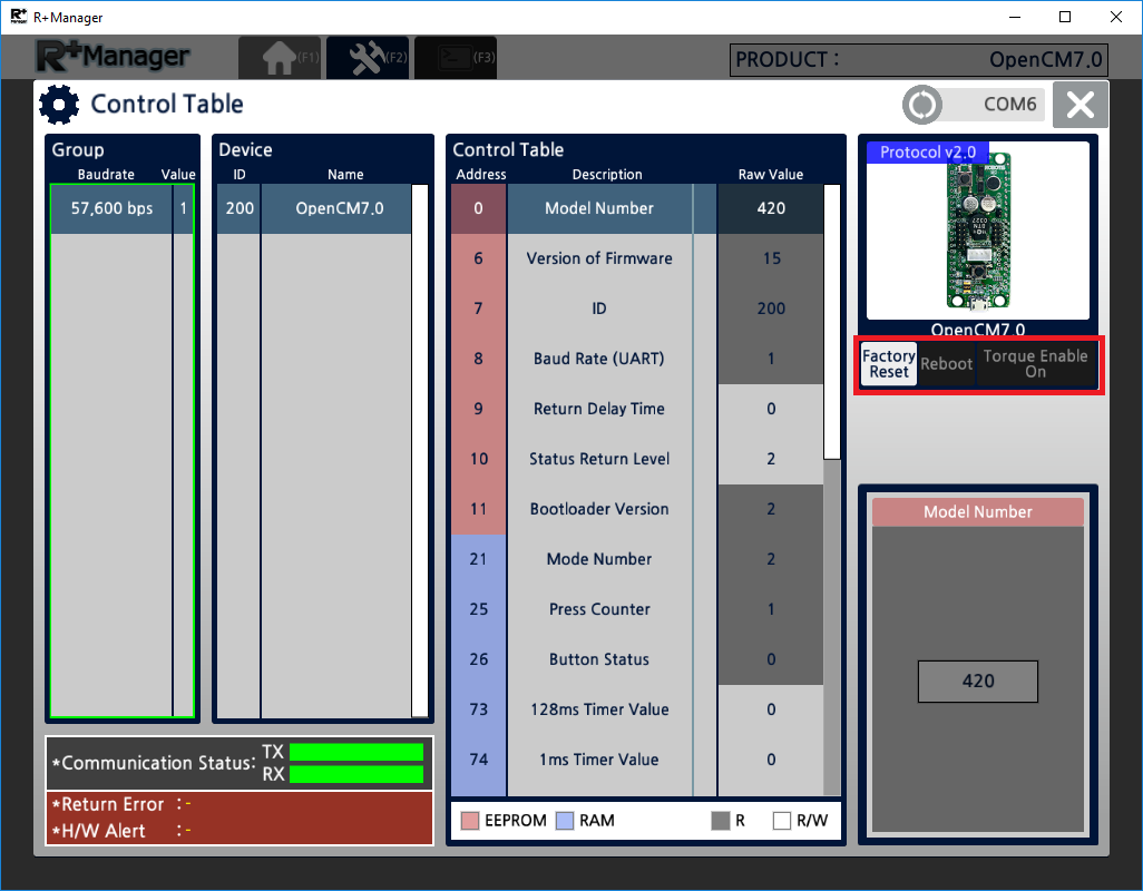
-
On the left bottom corner of the window, TX and RX communication status is visualized with colred bar (Green : normal, Yellow : timeout, Red : data loss)
Return Error will notify response status of the device and H/W Alert will notify error status of the hardware.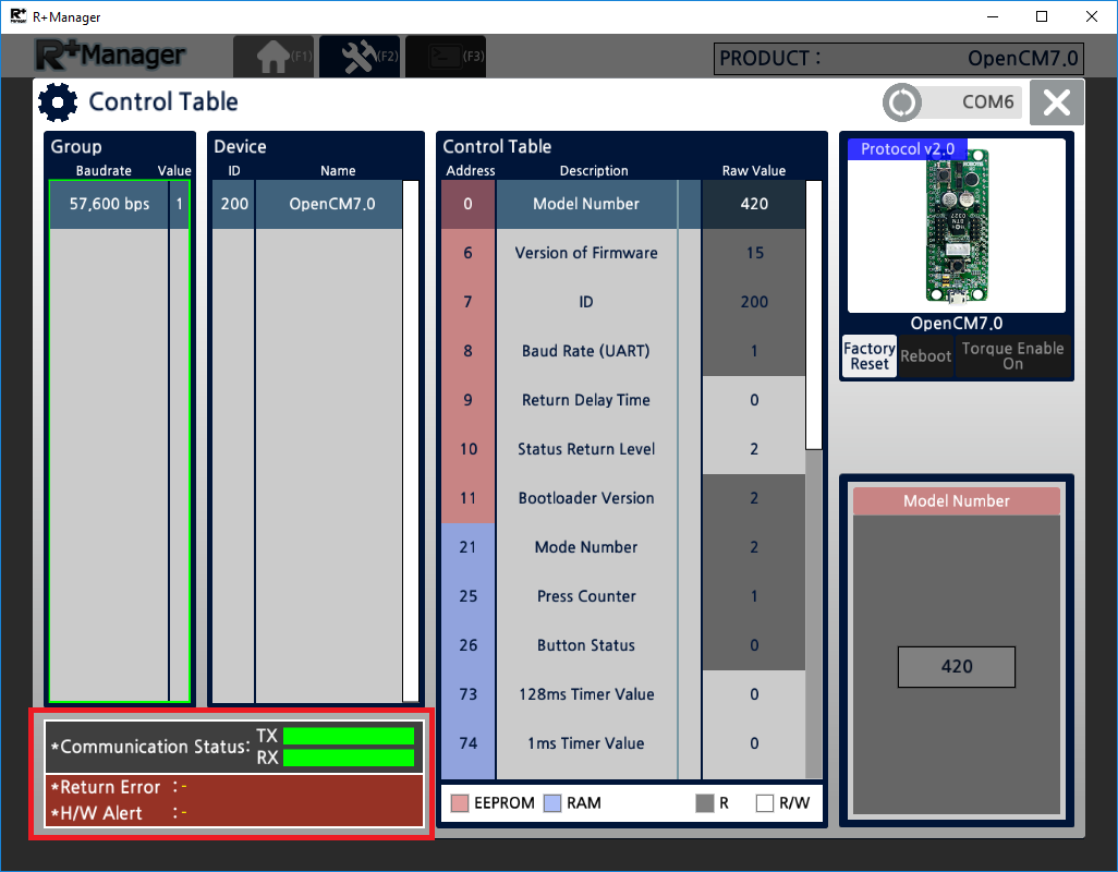
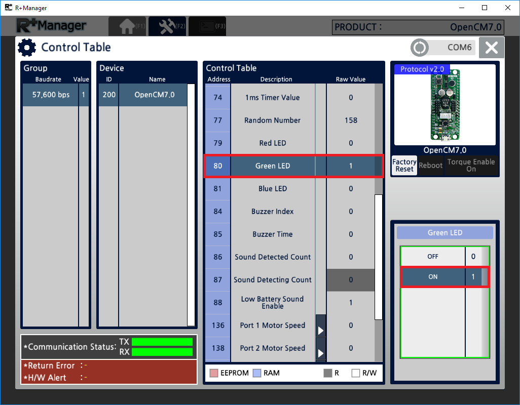
-
Select an item with RW access property and change its value to test controller. For below example, select Green LED and change its value from the right table will control green LED on the controller.
-
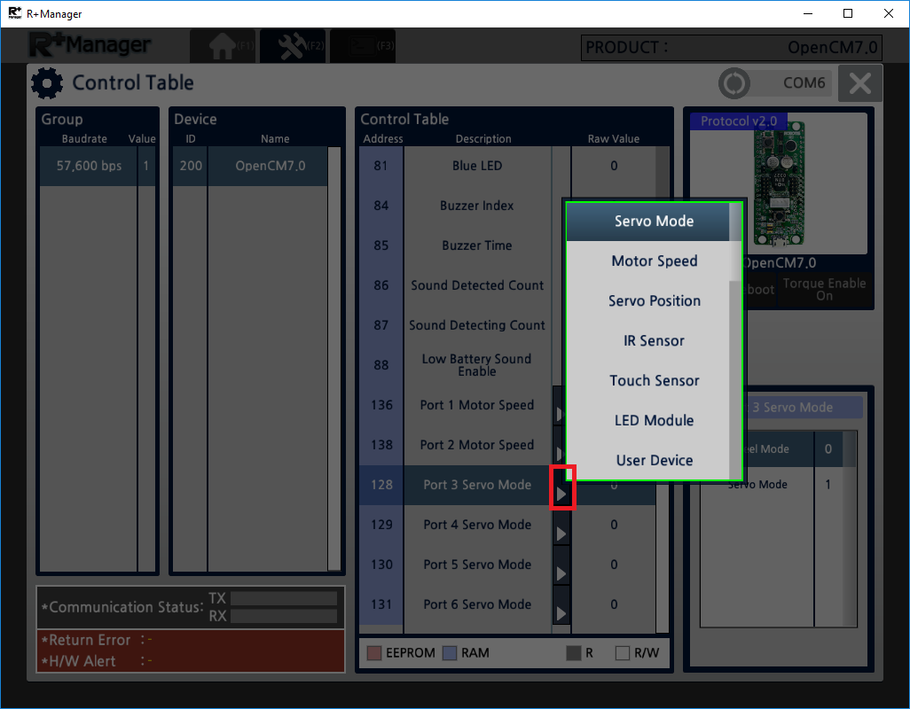
Various peripheral devices can be attached and tested. Click the extention triangle button to display sensor selection pop up window.
-
Changing peripheral device will also change the address for the device. In the below example, selecting Ultrasonic sensor for port 3 will update its address to 244.
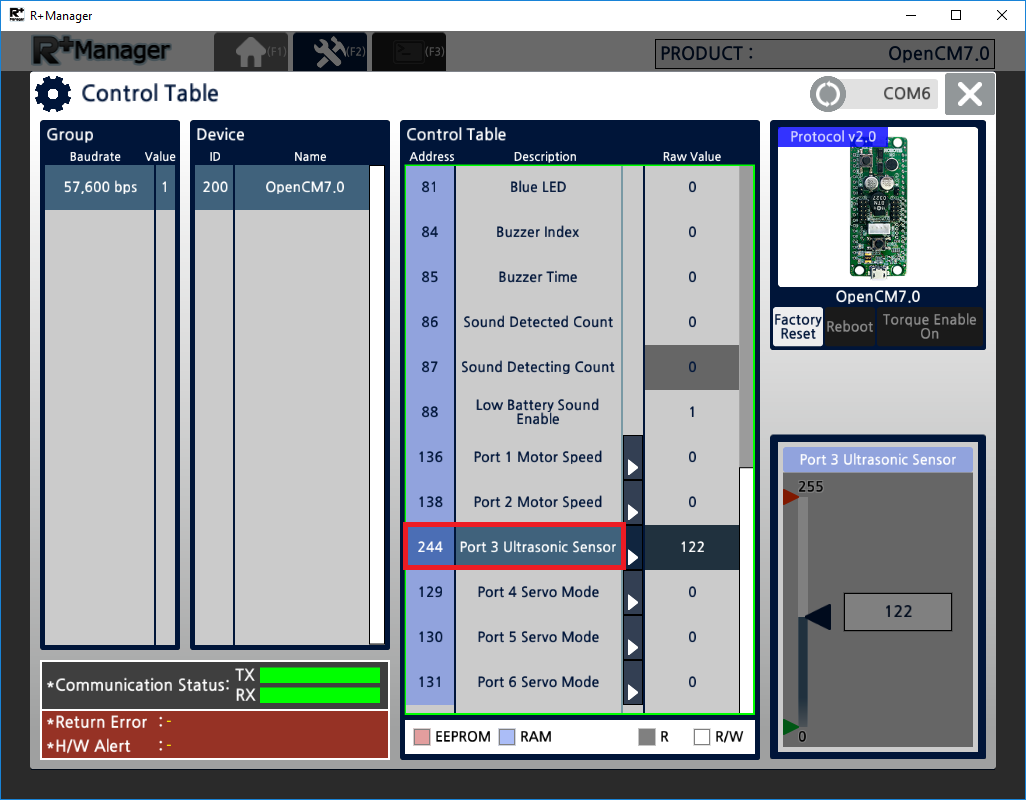
NOTE : For more details on peripheral devices, please refer to R+ Task 2.0.
Reference
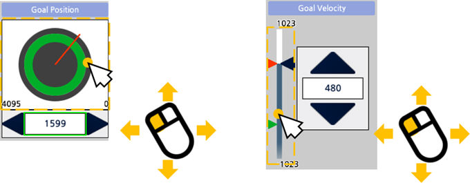
Changing Control Value
Use the left mouse-button to drag and change the value(used when changing the value in large amounts.)
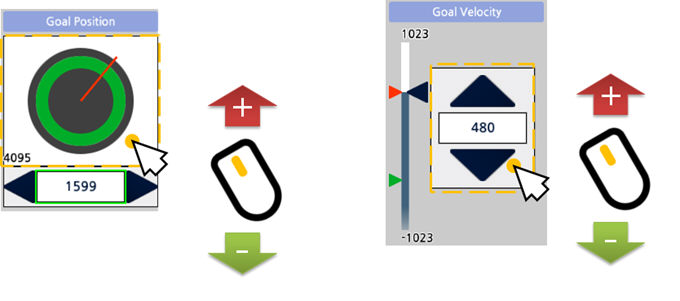
Use the mouse wheel to change the value (used when changing the value in small amounts.)
Use the arrow keys in the keyboard to change the value (used when changing the value minutely.)
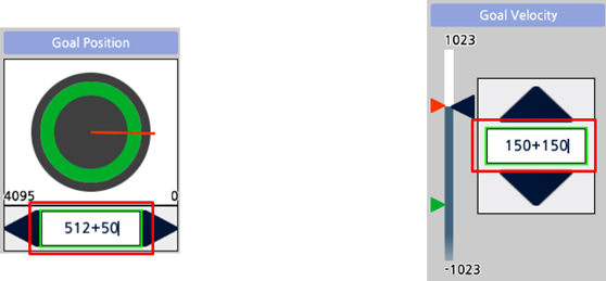
Inputting the value directly. You can also use basic arithmetic operations (addition, subtraction) to set the value.
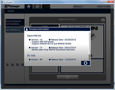
Firmware Information
This is the function to check the Firmware version, release date, and update note.
- In the Home Tab, select the product for which you wish to check the Firmware version.
-
Click on the “Firmware Information” button on the upper right corner.

-
You can check the Firmware version, release date, and update note of the selected product.
Firmware Management(Bluetooth)
By using the BT-210 or BT-110 you can manage the Firmware wirelessly (The BT-410 does not provide a wireless Firmware management function)
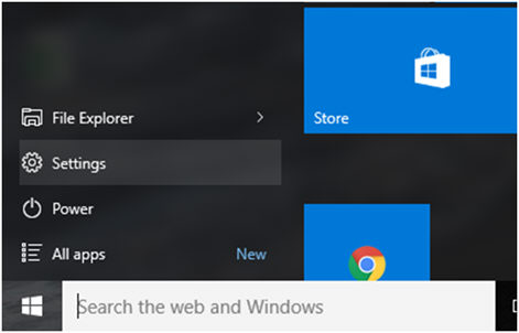
Add a Bluetooth serial port by following the instructions below (Example below shown for Windows10).
- Connect the BT-210(or BT-110) to the Controller and turn on the Controller.
-
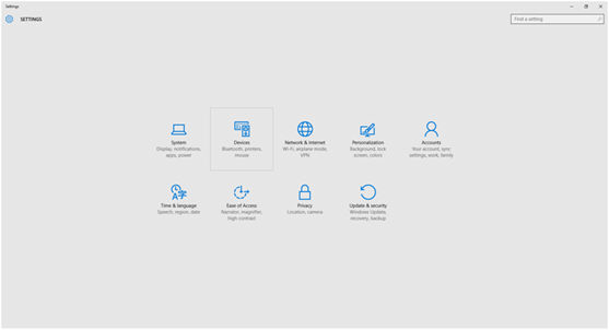
Click on the Windows start button, and select the Settings menu.
-
Click on the Devices menu.
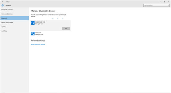
- Select the Bluetooth category on the left, and turn on the Bluetooth option on the right.
-
Select the searched Bluetooth module, and chick the Pair button.
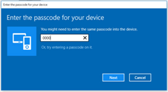
-
In the device password field, enter 0000 and click on the Next button.
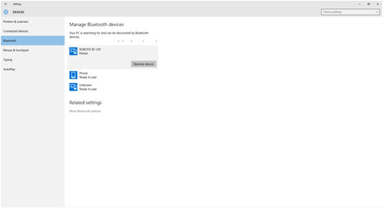
-
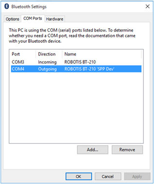
When the pairing is complete, select the paired device and click on “More Bluetooth options” found below.
-
Click on the COM Port tab and check the port number of the transmission port. (In the example below it was COM7)
-
In R+ Manager 2.0, select the installed Bluetooth port number and you can now manage the Firmware wirelessly.