Introduction
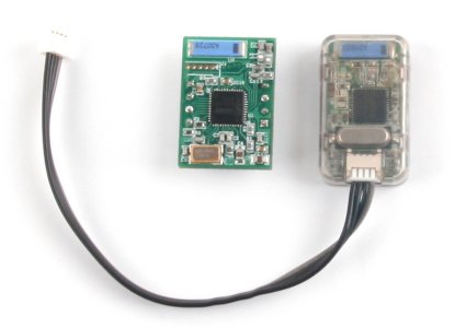
ZIG-100/110A
CAUTION : ZIG-100/110A is DISCONTINUED.
ZIG-100/110A, using Zigbee communication, makes serial communication (UART) possible. ZIG-100 and ZIG-110A provide equal functions; the only difference is the interface with the parts to be installed. The connectable parts are as follows:
(Please refer to the explanation pages on each part on how to install.)
- ZIG-100 : CM-5, ZIG2Serial, RC-100
- ZIG-110A : CM-100, CM-510, CM-530, CM-700
One set is composed of two units of ZIG-100/110A for sale, and it can be used immediately without setting separate ID since the ID of other module has been already set from the beginning of purchase. (Please be careful not to lose one of the set.)
Example
- Controlling OLLO Bug using Zigbee Communication ( ZIG-110A set is used. )
- Installing ZIG-110A to OLLO Bug Controller(CM-100)
- Installing ZIG-100 to Wireless Controller(RC-100)
- Controlling Bioloid Premium Kit in PC using Zigbee Communication ( ZIG-110A set is used. )
- Connecting to the serial port of PC after installing ZIG-100 to ZIG2Serial
- Installing ZIG-110A to Bioloid Premium Kit Controller(CM-510 / CM530)
CAUTION : Connect the modules while power is off. Connecting while power is on could result in malfunction.
Specifications
| Item | Description |
|---|---|
| Weight | ZIG-100 : 3.1g, ZIG-110A : 5.7g |
| Dimension | ZIG-100 : 19mm * 27mm * 9mm (6mm, the height excluding connector) ZIG-110A : 18.1mm * 30mm * 9.1mm |
| Frequency | 2.4GHz |
| Bandwidth | MAX 250kbps |
| Operation Voltage | 2.7V ~ 3.6V (3.3V Recommended) |
| Current Consumption | 30mA (at 3.3V) |
| Default baud rate | ZIG-100 : 57,600bps, ZIG-110A : 57,600bps |
How to Use
RoboPlus
Chaning wireless ID of others and setting to broadcasting mode can be done with the two methods as below. The appropriate method can be chosen depending on the users’ hardware composition.
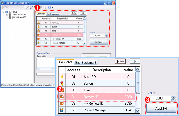
Connected to the Controller
- RoboPlus Manager can be executed after connecting ZIG-100 or ZIG-110A.
- If the appropriate port is selected and it is connected to the controller, the following widow can be seen.
- In the controller management window, if others’ wireless ID is selected, the value can be set in the subsidiary control window on the right.
-
If the “Apply” button is pressed after setting the desired value, the value is set.
Connected to ZIG2Serial
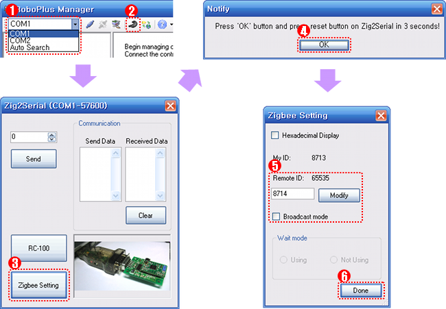
- RoboPlus Manager is executed after connecting ZIG-100 to ZIG2Serial.
- ZIG2Serial-connected port is selected, and the ZIG2Serial setting icon is clicked.
- ZigBee setting button is clicked, and the direction indicated in the window is proceeded.
-
If the setting window is popped up to set the desired value, and then the value is set by clicking change button.
Terminal
Use the terminal program for the Zig2Serial and Serial Communication to set the ZIG-100(The directions here are based on the RoboPlus Terminal)
- Connect the ZIG-100 on the Zig2Serial, then open the terminal program
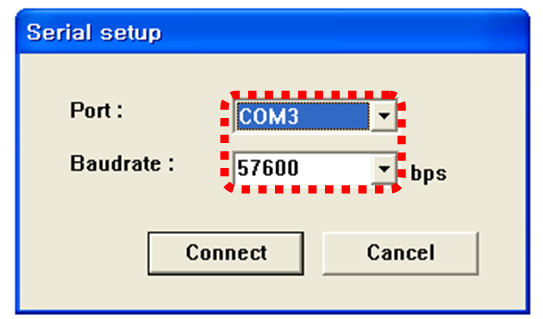
-
Open the port using the serial number of the PC which the Zig2Serial is connected
- While pressing on “1” (Shift+1) on your keyboard also press the reset switch on the Zig2Serial. When “!” is input during the ZIG-100’s booting, the setting mode is set to run. This screen will appear when you succeed.
- Baudrate : The baud rate set on the ZIG-100
- My-ID : ZIG-100’s exclusive unchangeable ID
-
Dest Addr : ID of the opposite party’s zigbee
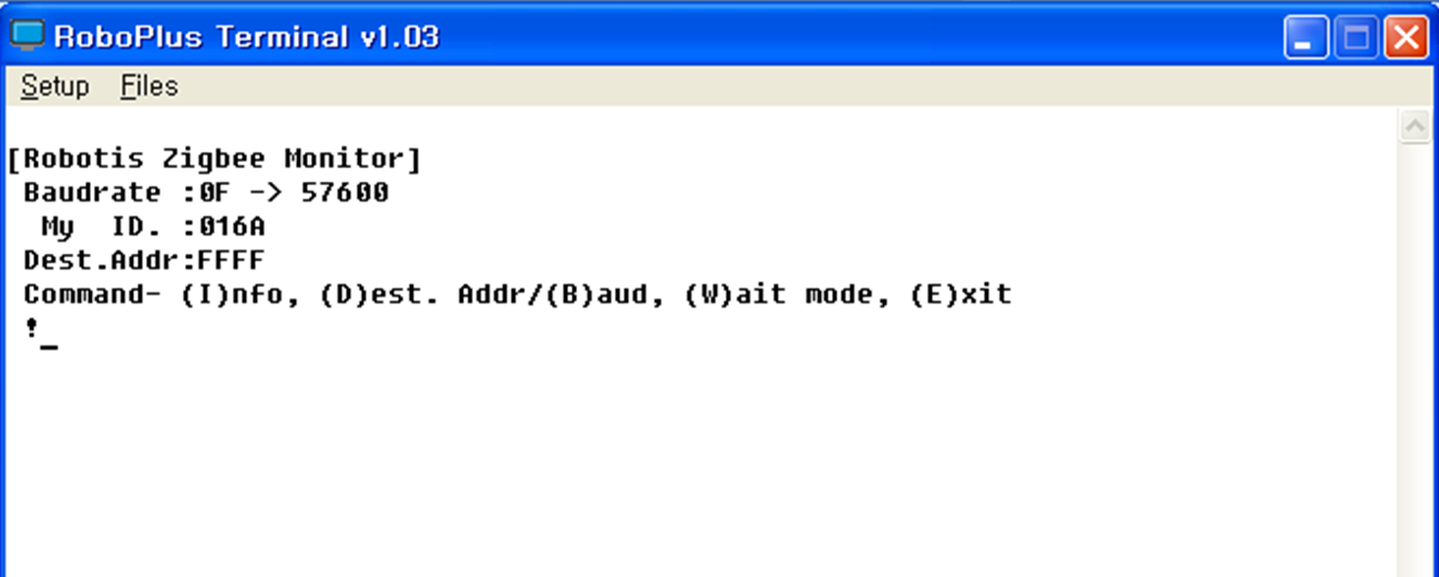
- Set the ZIG-100 using commands. Applicable commands as follows :
Ikey : Check the ZIG-100 current set valueDkey : Designate the opposite party’s ZIG-100 ID. Must input a hexadecimal. You can access Broadcat Communication Mode by inputting FFFF.-
Bkey : Change the ZIG-100’s baud rate. Must input a hexadecimal.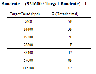
Wkey : Designate Waiting Mode. This can only be done when not in Broadcast Mode.Ekey : End Setting Mode. End by pressing the reset switch on the Zig2Serial
Communication Mode
Depending on the settings of ZIG-100 and ZIG-110A, 1:1 communication, 1:N, or N:N communcation can be performed.
1:1 Communication
- From a pair of ZIG-100 or the set value of ZIG-110A module, If one and the other’s wireless ID is pointing each other, it becomes 1:1 communication.
- If the power is impressed at the beginning, red LED flickers, and shortly it is recognized, the red LED is turned on continuously.
1:N Communication
- ZIG-100 module can be set to Waiting Mode.
- The module of Waiting Mode ignores others’ ID.
- The Waiting module of other ZIG-100 and ZIG-110A module must be set to others’ ID.
- Multiple ZIG-100 and ZIG-110A module can set Waiting module using others’ ID.
- If the power is impressed at the beginning, red LED filickers, and then if the module of Waiting mode and the module indicating the Waiting mode module recognize each other, the red LED is turned on continuously.
- At this moment, once it is connected, the connection is continued unless the power is turned off.
- If multiple modules try to connect to the module of Waiting mode at the same time, it continues the comunication with the first connected module.
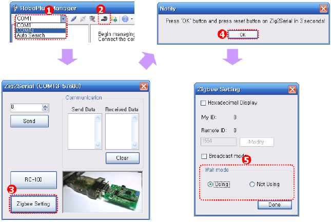
- How to set to Waiting mode is as below.
-
Communicates with the initial connected module; other modules’ signal maintain the standby status.
N:N Communication
- ZIG-100 or ZIG-110A module can be set to Broadcasting mode.
- If it is se to Broadcasting mode, all modules set to Broadcasting mode transmits and receives their data.
- Generally it is used to transmit a command from a module to all other modules.
- ZIG-110A : Broadcast channel is unchangeable (Default Value : 4)
- ZIG-100 : The broadcast channel can be changed based on the zigbee’s pin status
- ZIG-110A can be entered by setting the ID of the other party to hexadecimal FFFF.
Pinout
ZIG-100
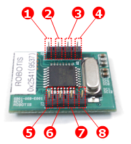
- GND : Ground Level of Zigbee Module (0v)
- VCC : Supply Voltage of Zigbee Module ( 2.7~3.6V )
- LED : LED to inform the connection stautus of Zigbee Module
- /RESET : Used to reset Zigbee Module (Also, used when it is entered Zigbee setting mode)
- RXD : Receive Signal Terminal of Zigbee Module
- TXD : Transmit Signal Terminal of Zigbee Module
- CHANNEL_SEL1 : Used in Broadcasting Mode
- CHANNEL_SEL2 : Used in Broadcasting Mode
| Channel | Pin Status |
|---|---|
| 1 | CHANNEL_SEL1 => Low CHANNEL_SEL2 => Low |
| 2 | CHANNEL_SEL1 => High CHANNEL_SEL2 => Low |
| 3 | CHANNEL_SEL1 => Low CHANNEL_SEL2 => High |
| 4 | CHANNEL_SEL1 => High CHANNEL_SEL2 => High |
ZIG-100 pin status according to the Broadcasting Channel information
ZIG-110A
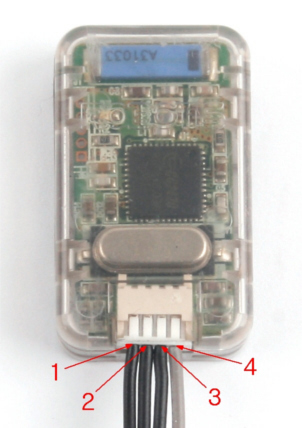
- RXD : Receive Signal Terminal of Zigbee Module
- TXD : Transmit Signal Terminal of Zigbee Module
- VCC : Supply Voltage of Zigbee Module ( 2.7~3.6V )
- GND : Ground Level of Zigbee Module (0v)
WARNING : Make connections to the controlled while unpowered. Making connections while the controller is powered may cause it to malfunction or/and damage.
Tutorials
- Zigbee SDK
Control ZIGBee via Zigbee SDK (C language)


