Introduction
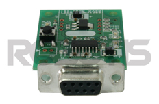
ZIG2Serial
- Chaning the ID of ZIG-100 : the ID can be changed through RoboPlus Manager.
- Serial communication with Bioloid through Zigbee communcation in PC
- The program for PC must be created separately.
- Communication test can be done with RoboPlus Manager.
Specifications
| Item | Description |
|---|---|
| Weight | 11.12g |
| Dimension | 56mm x 34mm x 12mm |
| Operating Voltage | 4.5V ~ 5.5V |
| Baud Rate | 57,600bps |
Layout
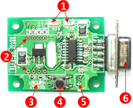
| Item | Description |
|---|---|
| Communication Status Display LED | If there is an outgoing signal through ZIG-100 in RS-232, TXD is turned on; if there is an incoming signal through ZIG-100, RXD is turned on. |
| ZIG-100 Connector | It is to connect ZIG-100 to ZIG2Serial. |
| ZIG-100 Status Display LED | The status of ZIG-100 is displayed. - If it is turned off : ZIG-100 is not connected or in set status. - If it is turned on : It is connected to other ZIG-100 and thecommunication is ready. - If It flickers : Other ZIG-100 has not been found. |
| Reset Switch | It is used when ZIG-100 is rebooted. |
| Power Connector | The power of 5V is needed to operate ZIG2Serial. The user can supply power using this connector. If it is connected to USB2DYNAMIXEL, a separate power supply is not necessary. |
| RS232 Connector | It can be connected to RS-232 port of PC. |
Pinout
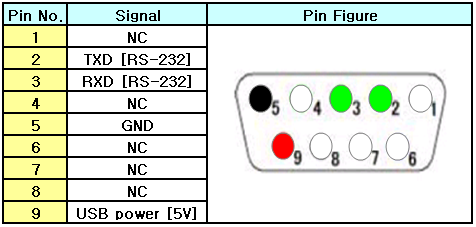
How to Use
Connect to PC
There is RS-232 Connector for communication in PC; it is called serial port. RS-232 connector of ZIG2Serial can be connected here. If there is no serial port in PC, USB2Serial converter must be purchased.
Supply Power
The power of 5V mus be supplied to operate ZIG2Serial. The power can be supplied using the power connector of ZIG2Serial. The cable for power connection must be made referring to the pin arrangement as below.
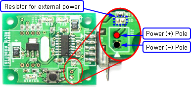
Zero ohm resistor must be attached or connected by soldering on the location of resistor for external power to supply the external power.
If USB2DYNAMIXEL products of Robotis are used, those products can be used without supplying separate power since the power is supplied from USB2DYNAMIXEL to ZIG2Serial.
WARNING : If the resistor for external power connection is connected, please use after removing the resistor.
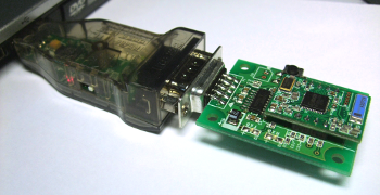
Connect ZIG-100
Please be careful with the direction of ZIG-100 when it is connected.
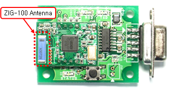
Select Broadcast Channel
You can select the Broadcast channel on the ZIG-100 by using the CHANNEL_SEL 1,2 pins.
The connection status must be changed to select the channel on the Zig2Serial.
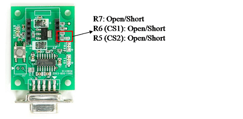
- Open is eliminating the lead which is not connected.
- Short is using the lead to connecting it.
- The resistance on the R5 and R6 is 0Ω. Thus you can eliminate or short the lead.
- The default setting of the Zig2Serial is set at channel #1 and R5, R6, and R7 are short. Easily select channel #1 and #4 by opening and shorting the lead on R7.
NOTE : When the ZIG-100 is mounted on the CM-5, the broadcast channel to set at #1. If the channel of the Zig2Serial is set differently, it will communicate with the CM-5 in broadcast communication mode.
| Channel | Connection Status of the Zig2Serial |
|---|---|
| 1 | R7 => Short R6 => Short R5 => Short |
| 2 | R7 => Short R6 => Open R5 => Short |
| 3 | R7 => Short R6 => Short R5 => Open |
| 4 | R7 => Short R6 => Open R5 => Open |
| 4 | R7 => Open R6 => Don’t care R5 => Don’t care |
Tutorials
-
RoboPlus Manager : The set value of Zig-100 and Zig-110 can be set through RoboPlus Manager.
-
Zigbee SDK : Zigbee can be controlled through Zigbee SDK in C language.
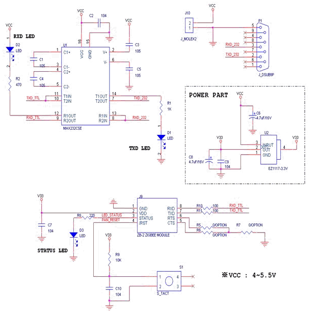
Circuit
