
Programming
Controller Parameters
Remocon TXD
This parameter is used to transmit data via a wireless communication module (IR, zigbee module).
- The data must be a number/value between 0 & 65535 transmitted or sent, wirelessly (IR or Zigbee).
- When the “Remocon TXD” parameter is set, the data is immediately sent wirelessly.
NOTE : Compatiable Controllers : CM-100, CM-5, CM-510, CM-530, CM-700
Example
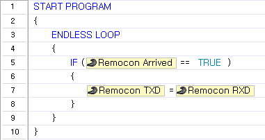
In the example below, the program waits for data, and when the data arrives, the received data is transmitted wirelessly.
It is commonly used to send a response to the control program on a PC connected using ZIG2Serial.
Remocon RXD
This parameter is used to read the received data received via the wireless communication module (IR, zigbee module).
- The data is a number between 0 and 65535.
- The [Remocon Arrived] parameter can be used check for new data.
- You can save up to maximum 2 wireless data by using a receiving buffer.
- When 2 data are saved in the receiving buffer, firstly received data will be read at first, and the remaining data will be read at second according to the received order. If there is only 1 data value in the buffer, when READ is executed, the latest data will be retrieved.
NOTE : Compatiable Controllers : CM-100, CM-5, CM-510, CM-700
Example
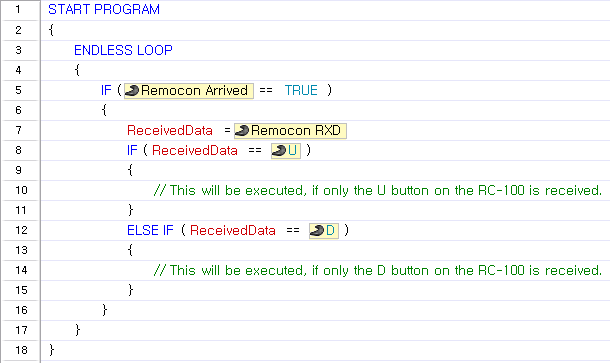
The code below shows how to control movement direction using the RC-100.

Remocon Arrived
This parameter is used to check whether there are any new data received via the wireless communication module(IR, zigbee module).
This value is either TRUE or FALSE.
- TRUE ( 1 ) : There is new data in the input buffer.
- FALSE ( 0 ) : All data in the input buffer have been retrieved.
NOTE : Compatiable Controllers : CM-100, CM-5, CM-510, CM-530, CM-700
Example
The code below shows how to control movement direction using RC-100.
Normally used to check whether new data has been received to process.
Aux LED
This parameter is either TRUE or FALSE and used to read and set the controller’s Aux LED status.
- TRUE (1) : When the Aux LED parameter is set to TRUE, the LED will turn on. When the Aux LED parameter is read, a value of TRUE signifies that the LED is on.
- FALSE (0) : When the Aux LED parameter is set to FALSE, the LED will turn off. When the Aux LED parameter is read, a value of FALSE signifies that the LED is off. False means that the input buffer is empty. i.e either no data has been received or all data has been retrieved
NOTE : Compatiable Controllers : CM-5, CM-510, CM-530, CM-700
Example
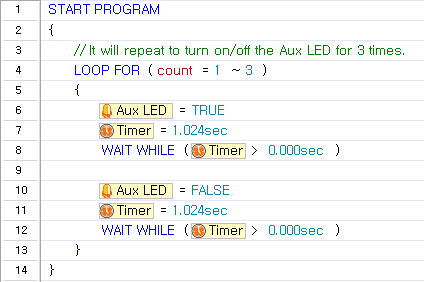
In this example, the Aux LED is turned on and off for 1 second 3 times.
Button
This parameter is used to read the controller’s button status.
- For CM-5, CM-510, CM-530
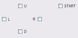
- Each button is assigned a unique value as follows.
- R button : 1, L button : 2, D button : 4, U button : 8, START button : 16
- When several buttons are pressed, the value assigned to the pressed buttons are added and read.
- Even if you do not know the buttons’ code values, you can easily determine which buttons have been pressed by using the buttons’ constant values.
- For OpenCM9.04
- Use of true/false constants
- When button is pressed(ture), When button is not pressed (false)
NOTE : Compatiable Controllers : CM-5, CM-510, CM-530, CM-700, OpenCM9.04
Example
This example shows how to perform different motions depending on which button is pressed.
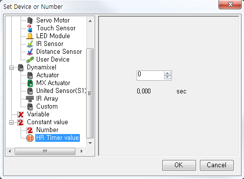
Timer
This parameter is used read the timer’s current value or to set the timer, which begins to count down automatically. The timer is located in the controller.
You can use “Timer value” constant to set the timer’s value.
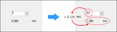
When a decimal number is entered, it will automatically be converted to the corresponding timer value. The actual timer value is between 0 and 255. Each timer value is 0.128 seconds. If you set a value greater than 0 in the timer parameter, the timer will start to count down every 0.128 seconds.
NOTE : Compatiable Controllers : CM-100, CM-5, CM-510, CM-530, CM-700
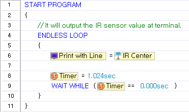
Example
The code below will print the value from the Center IR sensor every second.
HR Timer
Internally the controller sets a counter; this is the parameter for the high resolution timer. This timer is set for every 1ms, useful for more accurate timing.
- You can use “Timer value” constant to set the timer’s value.
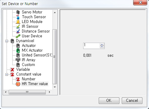
- When a decimal number is entered, it will automatically be converted to the corresponding timer value.
- The actual timer value is between 0 and 65535. Each timer value is 0.001 seconds.
- If you set a value greater than 0 in the timer parameter, the timer will start to count down every 0.001 seconds.
NOTE : Compatiable Controllers : CM-530
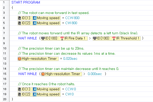
Example
While in fast forward motion the timer can help the tires react faster upon detection of a line.
Remocon ID
This parameter is used to set or read the currently set remote control ID. Please note that the controller will not receive any data if this parameter does not match the ID of the transmitting remote.
- The ID is a number between 0 and 65535.
- When the opponent’s ID is set to 65535(0xFFFF, in hexadecimal), it will send data to all Zigbee modules, regardless of ID.(Broadcasting Mode)
NOTE : Compatiable Controllers : CM-5, CM-510, CM-530, CM-700
Example
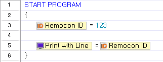
This example sets the opponent’s wireless ID to “123”, reads the value, and prints it on the screen.
- For seamless Zigbee communication, the opponent’s wireless ID must be set to the correct value.
- Using the broadcasting mode improperly may cause unforeseen problems.
My ID
- CM-100
- This parameter is used to determine whether or not a module ZIG-110 module has been installed.
- If a ZIG-110 wireless communication module is installed, TRUE(1) is returned. Otherwise, FALSE(2), is returned.
- Other Controllers : This parameter is used to read the ID of the Zigbee module installed in the robot.
- If a ZigBee module is installed, its ID is read (a number between 0 and 65534). If not, 65535 (0xFFFF in hexadecimal) is returned.
NOTE : Compatiable Controllers : CM-100, CM-5, CM-510, CM-530, CM-700
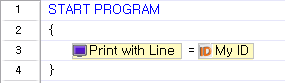
Example
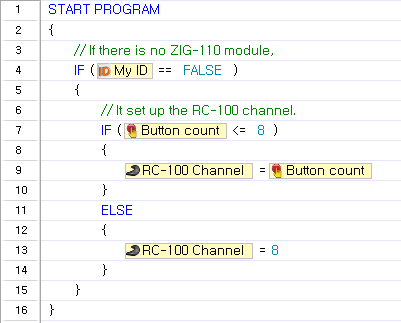
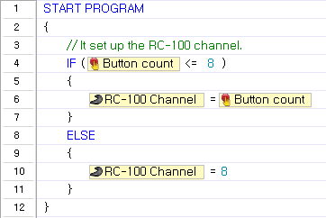
This example checks whether a ZIG-110 module is installed in the CM-100 controller. If the module is not installed, it sets the RC-100 channel according to the number of times the start button is pressed.
This example prints the ZigBee module’s ID. This code can be used with controllers other than CM-100.
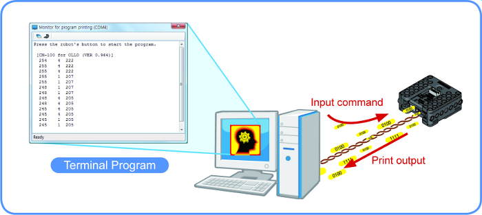
Print Program Output
Controllers usually do not have display devices the way a PC has a monitor, so it is hard to keep track of what goes on in a controller. Therefore, a “terminal” is used to “borrow” the PC’s monitor.
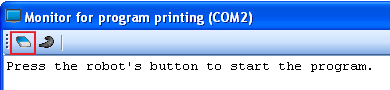
Open the Program Output Monitor
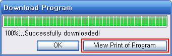
To see the output of the program, you must open the Program Output Monitor BEFORE executing the program. There are three ways to open the Program Output Monitor.
-
Click the ‘View Print of Program’ on the Download Program window.
- Click the
View Print of Programbutton in the tool bar. - Press
F5or click onView Print of Program(V)menu under Program(P).
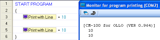
Print/Print with Carriage Return
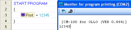
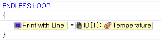
Use the “Print” parameter in your task code to see desired values on the screen.
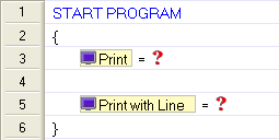
Print : Print the value, then move the cursor to next line.
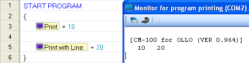
Print with New Line: Print out the value, and move the cursor to next line.
Error : Please check the following
- Values from the controller
-
A welcome screen is shown when the program starts
-
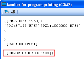
Error messages during program operation([Error Messages])
-
-
Values from task code : All decimal numbers between -32767 and +32767 can be displayed(Printing characters or custom messages is not possible).
-
To print numbers
-
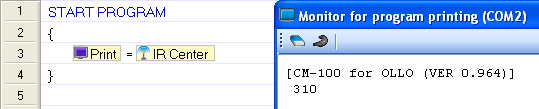
To print values from sensors
-
Clear Screen
You may erase everything on the screen.
IR Left/Center/Right
This parameters are used to read the IR sensors’ values.
- The sensor value is between 0 and 1023.
- For objects with the same or similar color, the closer it is, the higher the value(closer to 1023), and the farther away it is, the lower the value (closer to 0).
- For objects with the same distance, the lighter(white) the object, the higher the value, and the darker(black) the object, the lower the value.
NOTE : Compatiable Controllers : CM-100
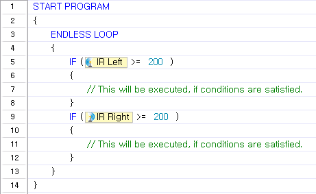
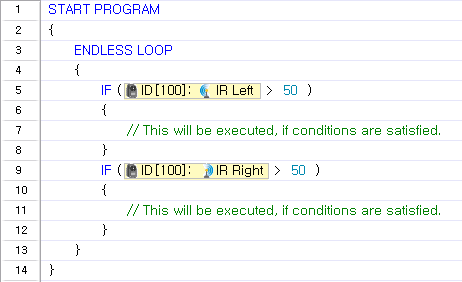
Example
In this example, specific motions are performed when only the left IR sensor detects an object or when only the right IR sensor detects an object..
- Sensor values may be affected by external lights which emit infrared rays such as sunlight or a fluorescent lamp.
- Sensor values depend on the object’s color or surrounding light, so using the IR sensor to measure the exact distance is not recommended.
- As above mentioned, IR sensor values are different if objects have different colors, even if they are the same distance away. This characteristic can be utilized to distinguish black from white(Can be used for tracing line).
Buzzer Index
This parameter is used to set the musical note or melody to be played or to retrieve the note or melody currently being played using the buzzers in the controller.
- The “Buzzer Time” parameter must always be used with the “Buzzer Index” parameter. “Buzzer Time” must be set before “Buzzer Index” is set. (The order is important) (Click here for more information on “Buzzer Time”.)
- Depending on what the “Buzzer Time” is set to, “Buzzer Index” can be set to play a musical note or a melody.
- When “Buzzer Time” is set to 255 : Melody Mode
-
Choose from 16 different melodies (0~15).

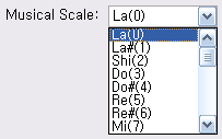
- When “Buzzer Time” is between 0 and 254 : Musical Note Mode
-
Choose from 27 notes. The selected notes will play for the length set as “ Buzzer Time”.
NOTE : Compatiable Controllers : CM-100, CM-510, CM-530
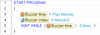
Example
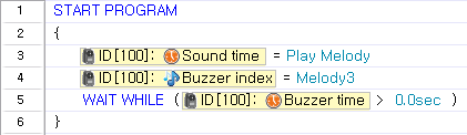
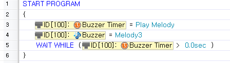
Plays melody 3.
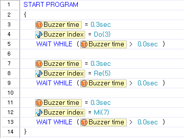
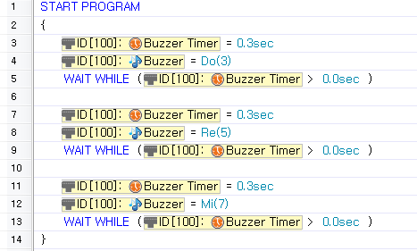
Plays Do, Mi and Sol for 0.3 seconds each.
Buzzer Time
This parameter is used to set how long the note or melody will be played or to retrieve how much longer it will be played.
- The “Buzzer Time” parameter is always used with the “Buzzer Index” parameter. “Buzzer Time” must be set before “Buzzer Index” is set. (The order is important) (Click here for more information on “Buzzer Time.”)
- “Buzzer Time” can be set to a value between 0 and 255.
- Each value represents 0.1 second. For example, when “Buzzer Time” is set to 1, the note will be played for 0.1 second. The maximum length a note will be played is 5 seconds. Therefore, when values between 50 and 254 are entered, the note will be played for 5 seconds.
- When “Buzzer Time” is set to 255 : Melody Mode
- Choose from 16 different melodies (‘0~15) .
-
When the melody finishes playing, “Buzzer Time” is reset to 0.
- When “Buzzer Time” is between 0 and 254 :Musical Note Mode
-
Choose from 27 notes. The selected note will play for the length set as “Buzzer Time.”
NOTE : Compatiable Controllers : CM-100, CM-510, CM-530
Example
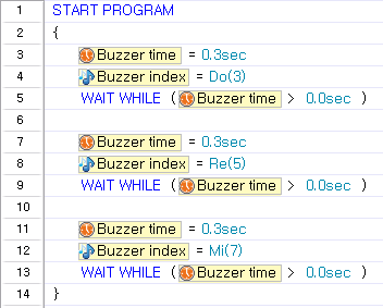
Plays melody 3. (Same as the example in “Buzzer Index”)
Plays Do, Mi and Sol for 0.3 seconds each.(Same as the example in “Buzzer Index”)
- “Buzzer Time” cannot be set while a note or melody is being played.
Sound Count
A controller equipped with a microphone has a function to count sounds when the sound is louder than a certain threshold. For example, it is possible to count claps. This parameter is used to retrieve the number of detected sounds.
- “Sound Count” uses the numbers between 0 and 255. As a result, the maximum number of sounds counted is 255.
- When the sounds are no longer detected, the number of detected sounds will be input into the “Sound Count” parameter.
- Because “Sound Count” is not initialized automatically, you have to reset it to 0 before use.
NOTE : Compatiable Controllers : CM-100, CM-510, CM-530
Example
Detects sounds and repeats a specific motion for as many times as it is detected.
- The geared motor connected to the controller may make loud noises while moving, which will be detected by the microphone. Please use the sound detection function only when the OLLO/Bioloid has stopped moving completely.
Current Sound Count
A controller equipped with a microphone has a function to count sounds when the sound is louder than a certain threshold. For example, it is possible to count claps. This parameter is used to retrieve the number of detected sounds.
- “Current Sound Count” uses numbers between 0 and 255. As a result, the maximum number of sounds counted is 255.
- The parameter value is increased in real-time whenever a sound is detected.
- If a new sound is not detected for 0.8 seconds, the value of the “Current Sound Count” parameter is passed to the “Sound Count” parameter, and the “Current Sound Count” parameter is reset to 0.
NOTE : Compatiable Controllers : CM-100, CM-510
Example
This code saves the current sound count in the “DetectionCount” variable.

This code pauses the program when no sounds are detected.

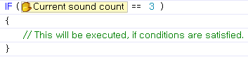
This code executes a block of code when 3 sounds are detected.
- When it is connected with controller, sometimes the sounds of geared motor can be too loud to be input in the controller in normal way. Please use the sound detection function only when the OLLO/Bioloid has stopped moving completely.
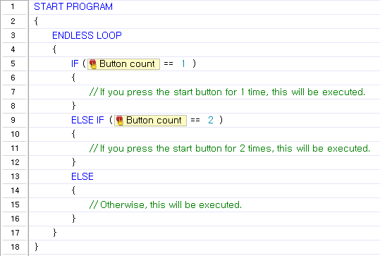
Button Count
This parameter is used to read how many times the START button was pressed when the controller was first turned on.
“Button Counts” uses numbers between 0 and 255. As a result, only up to 255 button presses can be counted .
NOTE : Compatiable Controllers : CM-100, CM-150
Example
The example executes different motions according to how many times the START button was pressed - once, twice, or more.
Powersave Timer
The controller has a hibernate function to conserve battery. If no commands are received for a set period, the controller can turn itself off. This parameter is used to set how long the controller will wait or how much time is left.
-
“Powersave timer” can be set using powersave constants.
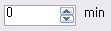
- “Powersave timer” uses numbers between 0 and 255.
- The unit is minutes (i.e., a value of 1 equals 1 minute)
- The default value is 5 minutes.
- Setting the “Powersave timer” to 0 will turn it off.
- The time remaining on the timer is always in minutes. For example, when 50 seconds remain, the timer will say that 1 minute remains.
NOTE : Compatiable Controllers : CM-100, CM-150
Example
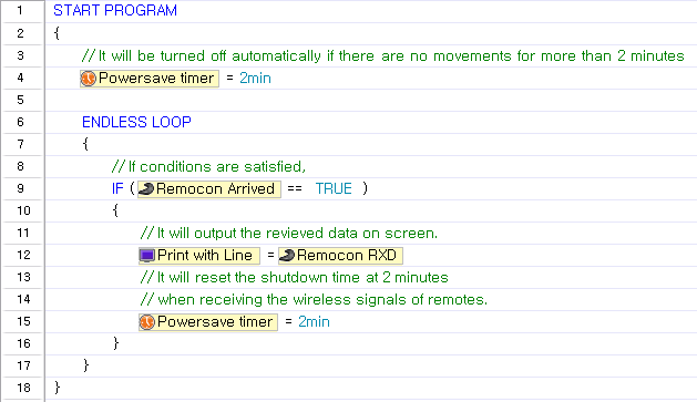
The controller will be turned off if no data is received for 2 minutes. If data is received, the timer is reset to 2 minutes.
- To keep the controller from turning itself off even when certain actions are performed, you must manually reset “Powersave timer.”
RC-100 Channel
This parameter is used to set up the infrared communication channel or to check the current channel between the controller’s IR receiver and RC-100.
-
The RC-100 channel can be set using constant numbers.
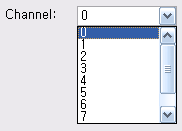
- “RC-100 Channel” uses numbers between 0 and 8.
- The Channel 0 is the special one that can be communicated with every other channels.
NOTE : Compatiable Controllers : CM-100, CM-510, CM-530
Example
Sets the RC-100 channel according to how many times the START button was pressed.
- For smooth infrared wireless communication, please refer to the section on how to set the channel for RC-100, and make sure that both RC-100 and the controller’s IR receiver are set to the same channel.
Motion Parameters
Motion Page
This parameter executes motions.
- When the motion page number is entered, the corresponding motion is executed.
- “Motion Page” can be read to see which motion is currently being executed.
- Certain page numbers can be used to stop the current motion.
- When the stop command is executed, “Number of Page Repeats” will be ignored.
- To confirm that a motion has stopped completely, check the motion status.
- When “Motion Page” is set to 0, the controller will execute to the Exit page and stop.
- When “Motion Page” is set to -1, the controller will execute to the current page and stop.
- If a page with no motions is set, an error message will be returned. (See error messages)
- “Motion Page” uses numbers between 1 and 255. (Some controllers use numbers between 1 and 127.)
NOTE : Compatiable Controllers : CM-5, CM-510, CM-530, CM-700
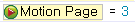
Example
Executes motion page #3.
Motion Status
This parameter is used to check the status of the motion.
- If a motion is being performed, 1 is returned. Otherwise, 0 is returned.
- True/False can also be used.
- True: Motion is being performed.
- False: Motion is not being performed.
NOTE : Compatiable Controllers : CM-5, CM-510, CM-530, CM-700
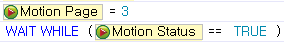
Example
Executes motion page #3 and waits until it is completed.
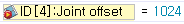
Joint Offset
To apply the joint offset to a robot, a motion must be performed after the “Joint Offset” parameter is set.
This parameter can be applied to each joint separately.
- -255 ~ 255 : The offset will be applied to the selected joint’s location value.
- Ex) If the location value of the joint with ID #3 is set as 300 → 400 → 500 in the motion data, and the joint offset is -100, the actual location value of the joint will be adjusted to 200 → 300 → 400.
- 1024 : If the joint offset is set to 1024, the selected joint will not be affected by the motion data during operation.
- Ex) This function can be used to control the location values directly, instead of the motion. A primary example is the Gripper, which should not move when a motion is being performed.
NOTE : Compatiable Controllers : CM-5, CM-510, CM-530, CM-700
Example
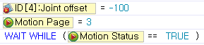
-
Set an offset value to a specific joint. While motion page #3 is being performed, set the offset of the joint with ID 4 as -100, and wait for the motion to finish.
-
Keep a joint from being affected by motion data Set up joint ID #4 to be unaffected while a motion is being executed.
Peripheral Devices
Peripheral devices are modules connected directly to the controller. The followings are peripheral devices.
Reduction Motor
This parameter is used to control the reduction motor’s direction and power (Speed). (Please refer to the Geared Motor GM-12A for more information)
- The reduction motor’s control values can be set using motor control constants.
-
The direction and power must be set together.
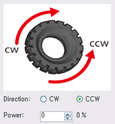
- CCW (Counter clock wise) 0 ~ 1023 : Decimal numbers between 0 and 1023
- CW (Clockwise) 0 ~ 1023 : Decimal numbers between 1024 and 2047
The control values are numbers between 0 and 2047.
NOTE : Compatiable Controllers : CM-100
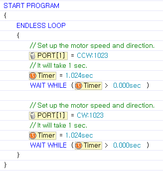
Example
In this example, the reduction motor connected to Port 1 will rotate in the clockwise direction for 1 second at maximum speed, before rotating in the counterclockwise direction for 1 second. These motions will repeat without end.
Tips
- Make sure the motor is connected to the correct port.
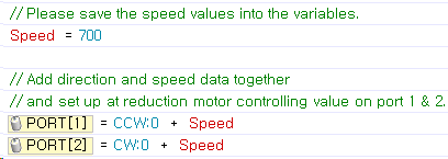
- Speed and direction can be controlled separately using motor control constants.
- In this example, the motor in Port 1 is set as “CCW:700”,and the motor in Port 2 is set as “CW:700.”
Servo Motor
This parameter is used to set the movements of servo motors. This parameter consists of 3 sub-parameters (move mode, speed, location), it helps to set up the movement of servo motor in more detailed way. (Please refer to the Servo Motor SM-10A for more information)
- Drive mode is set as either True or False.
- TRUE (1) : Operate in joint mode. In joint mode, the speed parameter is used to configure power output, and the location parameter is used to configure angular movement.
- False (0) :Operate in rotation mode. In rotation mode, the servo motor operates like a reduction motor, so only the speed parameter is used. The location parameter is ignored.
- Motor control constants can be used to set the speed (power).
- CCW (Counter clock wise) 0 ~ 1023 : Decimal numbers between 0 and 1023
- CW (Clockwise) 0 ~ 1023 : Decimal numbers between 1024 and 2047
- Location value constants can be used to set the location in joint mode.
- Uses decimal numbers between 0 and 1023.
- The red circle indicates the current values. The value can be set by dragging the jog dial with your mouse to the appropriate value.
- The maximum controllable angle is 300°. Thus, the minimum controllable angle, indicated by the location value of 1, is 0.29°.(300° / 1024 = 0.29°)
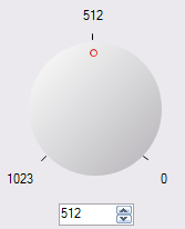
For detailed information about controllable angles, refer to the Servo Motor SM-10A.
NOTE : Compatiable Controllers : CM-100
Example
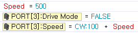
Set the servo motor at Port 3 in rotation mode and turn it clockwise with 600 outputs.
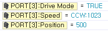
Set the servo motor at Port 3 in joint mode and move it to location 500 with maximum speed.
Tips
- Make sure the motor is connected to the correct port.
- The servo motor is not suitable for detailed control, as it lacks the precision and torque of DYNAMIXEL motor.
WARNING : If a program that controls LED modules is executed while another module (servo motor, IR module, etc.) is connected to the port, the module may be damaged.
Touch Sensor
This parameter is used to read the status of touch sensor (whether is was touched or not) (Please refer to the Touch Sensor TS-10 for more information)
While the sensor being touched, the returned value will be TRUE(1). However, if you take off your hands from touch sensor, the returned value will be reset as False(0).
NOTE : Compatiable Controllers : CM-100, CM-510, CM-700
Example
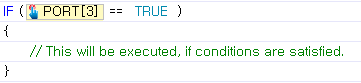
This example executes a block of code when the touch sensor at Port 3 is touched.
LED Module
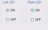
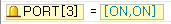
This parameter is used to turn on the LED or to read its current status. (Please refer to the LED Module LM-10 for more information)
-
LED module output constants can be used.
-
The actual values are numbers between 0 and 3. The following list shows what each value represents when setting or reading the LED module values.
- 0 : Turn off both LEDs.
- 1 : Turn on right LED only.
- 2 : Turn on left LED only.
- 3 : Turn on both LEDs.
NOTE : Compatiable Controllers : CM-100
Example
Turn on both LEDs connected to Port 3.
WARNING : If a program that controls LED modules is executed while another module (servo motor, IR module, etc.) is connected to the port, the module may be damaged.
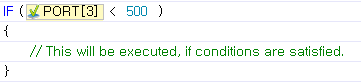
IR Sensor
This parameter is used to read the value of the IR sensor module. (Please refer to the IR Sensor IRSS-10 for more information)
- IR sensor values are numbers between 0 and 1023.
- For objects with the same or similar color, the closer it is, the higher the value (closer to 1023), and the farther away it is, the lower the value (closer to 0).
- For objects with the same distance, the lighter (white) the object, the higher the value, and the darker (black) the object, the lower the value.
NOTE : Compatiable Controllers : CM-100, CM-510, CM-700
Example
This example executes a block of code if the value of the IR sensor connected to Port 3 is less than 500.
WARNING : If a program that controls IR modules is executed while another module (servo motor, LED module, etc.) is connected to the port, the module may be damaged.
DMS Sensor
This parameter is used to read the value of the DMS sensor. (Please refer to the Distance Measurement Sensor DMS-80 for more information)
- DMS sensor values are numbers between 0 and 1023.
- For objects with the same or similar colors, the close it is, the higher the value (closer to 1023) and the farther away it is, the lower the value (closer to 0).
- Unlike IR sensors, DMS sensors are hardly affected by colors.
NOTE : Compatiable Controllers : CM-510, CM-700
Example
This example executes a block of code if the value of the DMS sensor connected to Port 3 is less than 500.
User Devices
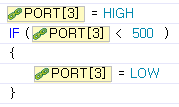
This parameter is used to set or read the values of user’s devices. (Please refer to the Custom Device for more information)
- Although the same address is used to read & write values, the actual port pins are different(Check user’s port pin information).
- The value read from the user’s device is the voltage level of the input port.
- The value read is a number between 0 and 1023.
- When the user’s device is set as 1, It will deliver 5V to the output port.
- Setting the user’s device as 1 does not guarantee that the value read from the user’s device will be 1.
- The output of the user’s device can be set using port value constants.
NOTE : Compatiable Controllers : CM-510, CM-700
Example
After setting the user’s device at Port 3 as 1 (high), if the value read value from Port 3 is less than 500, the output port is set as 0 (low).
DYNAMIXEL Parameters
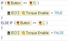
Torque Enable
This parameter is used to turn the motor’s torque on or off. It can also be used to determine whether the motor’s torque is currently on or off.
The value is either TRUE or FALSE.
- TRUE (1) : When set to TRUE, the motor’s torque turns on. When the parameter is read, a value of TRUE signifies that the motor’s torque is on.
- FALSE (0) : When set to FALSE, the motor’s torque turns off. When the parameter is read, a value of FALSE signifies that the motor’s torque is OFF.
Example
When the R button of the controller is pressed, the actuator with ID 1 will turn on. When the L button is pressed, it will turn off.
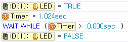
LED
This parameter is used to set or read DYNAMIXEL LED status.
The value is either TRUE or FALSE.
- TRUE (1) : When set to TRUE, the LED turns on. When the parameter is read, a value of TRUE signifies that the LED is on.
- FALSE (0) : When set to FALSE, the LED turns off. When the parameter is read, a value of FALSE signifies that the LED is off.
Example
Turns the LED on for 1 second and turns it off.
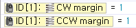
CW/CCW Margin
These parameters are NOT available for MX Series. These parameters are used to set or read the actuator’s margin value.
- Margin values are numbers between 0 and 254.
- The margin designates the area around the goal position that receives no torque.
- The recommended value is 1. Unless otherwise specified, use the recommended value.
Example
Set both margins as 1.
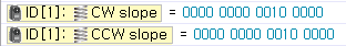
CW/CCW Slope
These parameters are NOT available for MX Series.
These parameters are used to set or read the actuator’s slope value.
- The slope value will be created at both CW/CCW directions, and the output level will be set near the target position.
- If you set the lower slope value, it will reach to the target position by reducing the initial power NOT that much. On the contrary, if you set the higher value, it will reach the target position by reducing considerable powers as it reaches to the goal.
- If you set the lower slope value, it will resist with maximum power not to stray from target position.
- Even if you set the higher value, it will resist with more and more power if it is strayed too much from target position.
- Compliance Slope will be changed into 7 Data representative values according to the input Data. In other words, if you input 25, in real operation, 16 -the representative value of 25-, will be used.
| Level | Real Data Value | Representative Data Value |
|---|---|---|
| 1 | 0 (0x00) ~ 3(0x03) | 2 (0x02) |
| 2 | 4(0x04) ~ 7(0x07) | 4 (0x04) |
| 3 | 8(0x08)~15(0x0F) | 8 (0x08) |
| 4 | 16(0x10)~31(0x1F) | 16 (0x10) |
| 5 | 32(0x20)~63(0x3F) | 32 (0x20) |
| 6 | 64(0x40)~127(0x7F) | 64 (0x40) |
| 7 | 128(0x80)~254(0xFE) | 128 (0x80) |
- Appropriate Compliance Slope, Power control, and the Compliance Margin values will make it possible to create smoother movement.
NOTE : Compatiable Controllers : CM-5, CM-510, CM-700
Example
Sets both slope values as 32. Binary numbers are used to set the parameter.
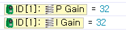
PID Gain
These parameters are NOT available for AX, DX, RX and EX Series. Parameters for the actuator’s set PID values.
- P gain refers to the value of proportional band. A small gap between vales grow bigger near the target value.
- I gain refers to the value of integral action.
- D Gain refers to the value of derivative action.
- Gains values are in between 0~254.
Example
Set the P and I value 32
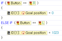
Goal Position
This parameters is used to set or read the actuator’s goal position.
- Position constants can be used.
- The value can be input directly, or set using the jog dial.
- The position values of AX, DX, and RX-series are numbers between 0 and 1023
- The position values of EX-series are numbers between 0 and 4,095
Example
When the R button of the controller is pressed, the goal position of the actuator with ID 1 will be set as 1. When the L button is pressed, the goal position will be set as 1023.
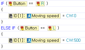
Moving Speed
This parameter is used to set or read the speed of actuator.
-
Motor control constants can be used.
- In joint mode, the direction value is meaningless, and only the power value will be used.
- In joint mode, set the value as 0 to output at maximum power.
- In endless rotation mode, the direction and power values must be set together.
- The joint mode or endless rotation mode can be set using at RoboPlus Manager. (Refer to “actuator mode”)
Example
When the R button of the controller is pressed, the speed of the actuator with ID1 will be set as 0. When the L button is pressed, the speed will be set as 500. (If the actuator is in joint mode, the speed of 0 equates to maximum output. )
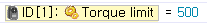
Torque Limit
This parameter is used to set or read the power status of actuator.
- Torque limit values are numbers between 0 and 1023 .
Example
Set the maximum torque of the actuator with ID 1 as 500.
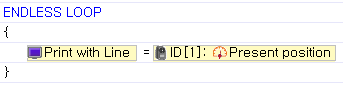
Present Position
This parameter is used to read the actuator’s current position.
- The current position of the actuator is read.
Example
Prints the present position of the actuator with ID 1 on the screen.
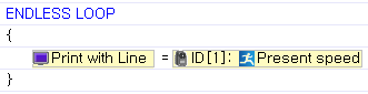
Present Speed
This parameter is used to read the actuator’s current speed.
- The current speed of the actuator is read.
Example
Prints the present speed of the actuator ID 1 on the screen.
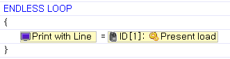
Present Load
This parameter is used to read the actuator’s current load.
- The current load of the actuator is read.
Example
Prints the present load of the actuator with ID 1 on the screen.
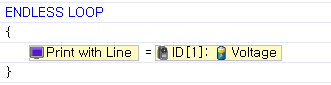
Voltage
This parameter is used to read DYNAMIXEL current voltage.
- The current voltage of DYNAMIXEL is read.
- The actual voltage is 1/10 of the read value. For example, if the returned value is 115, the actual voltage is 11.5V.
Example
Prints the current voltage of DYNAMIXEL with ID 1 on the screen.
Temperature
This parameter is used to read DYNAMIXEL current temperature.
- The current temperature of DYNAMIXEL is read.
Example
Prints the present temperature of DYNAMIXEL with ID 1 on the screen.
Moving
This parameter is used to determine whether the actuator is currently moving or not.
- The status of the actuator’s movement (whether it is moving or not) is returned.
- If it is moving, 1 is returned. If it is not, 0 is returned.
Example
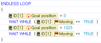
Sets the goal position of the actuator with ID 1 as 0, and waits for it to stop moving.
Sensed Current
This parameter is NOT available for AX, DX and RX Series. This parameter is used to check the current being consumed. You can read EX Series motor’s current with this parameter.
- If the value is 512, the currnet is 0 ampere. That is, there is no current flowing.
- If the value is larger than 512, the current is rotating the motor clockwise, and the size of the current is proportional to the size of the data. (1 = aprroximately 10 mA)
- For example, if the data is 612, 1A (612-512=100 => 100x10mA = 1,000mA) is being used to rotate the motor in the clockwise direction.
- If the value is smaller than 512, the current is rotating the counterclockwise, and the size of the current is proportional to the size of the data. ( 1 = aprroximately. 10 mA)
- For example, if the data is 312, 2A (512-312=200 => 200x10mA=2,000mA) is being used to rotate the motor in the counterclockwise direction.
Example
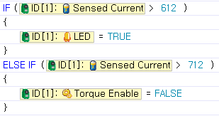
If the current of the EX motor with ID 1 is larger than 1A and flowing in the clockwise direction, the LED will turn on. Otherwise, If it is larger than 2A, the motor will be turned off.
Universal Sensor S1
IR Left/Center/Right
These parameters are used to read the current IR sensor value from the universal sensor(AX-S1).
- The current DMS sensor value of the universal sensor (S1) can be read.
- Sensor values depend on the object’s color and surrounding light, so using the IR sensor to measure the exact distance is not recommended.
- As mentioned above, IR sensor values are different if objects have different colors, even if they are the same distance away. This characteristic can be utilized to distinguish black from white. (Used for tracing lines)
- The sensor value is between 0 and 255.
Example
In this example, specific motions are performed when only the left IR sensor detects an object or when only the right IR sensor detects an object.
Tip
- Sensor values may be affected by external lights that emit infrared rays, such as sunlight or a fluorescent lamp.
- Sensor values depend on the object’s color and surrounding light, so using the IR sensor to measure the exact distance is not recommended.
- As mentioned above, IR sensor values are different if objects have different colors, even if they are the same distance away. This characteristic can be utilized to distinguish black from white. (Used for tracing lines)
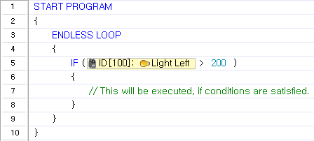
Light Left/Center/Right
This parameter is used to read the current light brightness from the universal sensor(S1).
- The current light brightness value of the universal sensor(S1) can be read.
- The intensity of radiation of near by light sources such as candles and light bulb can be measured.
- The sensor value is between 0 and 255.
Example
A block of code is executed when the left sensor detects brightness over 200.
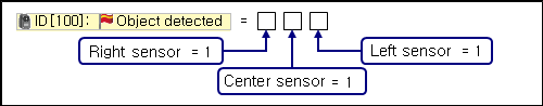
Object Detected
This parameter is used to determine whether an object is detected within a certain distance from an IR sensor (Left/Center/Right) of the universal sensor(S1).
- If an object is detected within a certain distance, the following values are returned.
- Binary numbers can be used for the bit values.
| Binary value | Decimal value | Meaning in Object Detected Commands |
|
|---|---|---|---|
| 000 | 0 | Not detected | |
| 001 | 1 | Detected by left sensor | |
| 010 | 2 | Detected by center sensor | |
| 011 | 3 | Detected by left and center sensors | |
| 100 | 4 | Detected by right sensor | |
| 101 | 5 | Detected by right and left sensors | |
| 110 | 6 | Detected by right and center sensors | |
| 111 | 7 | Detected by every sensor |
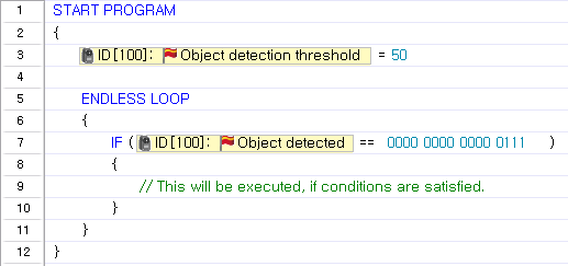
Example
The object detection threshold is set as 50, and a block of code will be executed when an object is detected within the threshold.
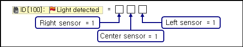
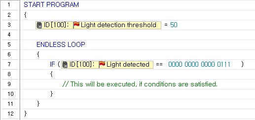
Light Detected
This parameter is used to determine whether a light is detected within a certain distance from an IR sensor (Left/Center/Right) of the universal sensor(S1). Compatible Controller
- If a light is detected within a certain distance, the following values are returned.
-
Binary numbers can be used for the bit values.
| Binary value | Decimal value | Meaning in Light Detection Commands |
|---|---|---|
| 000 | 0 | Not detected |
| 001 | 1 | Detected by left sensor |
| 010 | 2 | Detected by center sensor |
| 011 | 3 | Detected by left and center sensors |
| 100 | 4 | Detected by right sensor |
| 101 | 5 | Detected by right and left sensors |
| 110 | 6 | Detected by right and center sensors |
| 111 | 7 | Detected by every sensor |
Example
The light detection threshold is set as 50, and a block of code will be executed when a light is detected within the threshold.
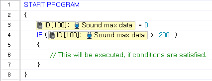
Sound Max Data
This parameter is used to set or read the maximum sound data of the universal sensor(S1).
- Reads the maximum sound data detected by the universal sensor(S1).
- If the detected volume is louder than the volume of the max sound data, the max sound data is replaced with the detected value.
- The value is between 0 and 255.
- Because “Sound max data” is not initialized automatically, the user must reset it 0 before use.
NOTE : Compatiable Controllers : CM-5, CM-510, CM-700
Example
Initialize “Sound max data” as 0 and execute a block of code when it exceeds 200.
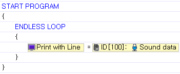
Sound Data
This parameter is used to read the current sound level of the universal sensor (S1).
- Reads the sound data of the universal sensor(S1).
- If no sounds are detected, the returned value will be near 127. When sounds are detected, the value will change according to the volume.
- The louder the sound, the more the value will fluctuate from 127 to 0 and 255.
- The value is between 0 and 255.
NOTE : Compatiable Controllers : CM-5, CM-510, CM-700
Example
Prints the current sound volume on the screen.
Sound Count
This parameter is used to read or initialize the number of sounds detected by the universal sensor(S1).
- “Sound Count” uses numbers between 0 and 255.
- When sounds are no longer detected, the number of detected sounds will be input into the “‘Sound Count” parameter.
- Because “Sound Count” is not initialized automatically, the user must reset it to 0 before use.
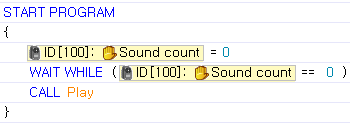
Example
Initializes “Sound count” as 0 and wait for a sound to be detected. Then, call the “Play” function.
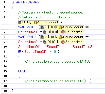
Sound Time
This parameter is used to set or read how long the sound will be played.
- The value is between 0 and 65535.
- When “sound count” is initialized as 0, “sound time” will be also initialized as 0.
Example
The following example uses two AX-S1 sensors to determine the direction of the detected sound.
Buzzer Index
This parameter is used to set or read the musical note played by the buzzer of the universal sensor (S1).
- The “Buzzer Time” parameter must always be used with the “Buzzer Index” parameter. “Buzzer Time” must be set before “Buzzer Index” is set for the correct sound to be played. (This order is very important) (Click here for more information on “Buzzer Time.”)
- Depending on what the “Buzzer Time” is set to, “Buzzer Index” can be set to play a musical note or a melody.
- “Buzzer Time” is set to 255 : Melody Mode
-
Choose from 26 different melodies (0 ~ 25).
- When “Buzzer Time” is between 0 and 254 : Musical Note Mode
-
Choose from 51 notes. The selected note will play for the length set as “Buzzer Time.”
Example
Plays melody #3.
Plays Do, Mi, and Sol for 0.3 seconds each.
Buzzer Time
This parameter is used to set or read how long the sound is played by the buzzer of the universal sensor (S1).
NOTE : Compatiable Controllers : CM-5, CM-510, CM-700
- “Buzzer Time” parameter must always be used with the “Buzzer Index” parameter. “Buzzer Time” must be set before “Buzzer Index” is set for the correct sound to be played. (The order is important.) (Click here for more information on “Buzzer Time.”.)
- “Buzzer Time” can be set using buzzer time constants.
- “Buzzer Time” can be set to a value between 0 and 255.
- Each value represents 0.1 second. For example, when “Buzzer Time” is set to 1, the note will be played for 0.1 second. The maximum length a note will be played is 5 seconds. Therefore, when values between 50 and 254 are entered, the note will be played for 5 seconds.
- When “Buzzer Time” is set to 255 : Melody Mode
- Choose from 26 different melodies (0-25).
-
When the melody finishes playing, “Buzzer Time” is reset to 0.
- “Buzzer Time” is between 0 and 254 : Musical Note Mode
- Choose from 51 notes. The selected note will play for the length set as “Buzzer Time.”
-
When it is set to 254, the sound will play without end.
Example
Plays melody #3 .
Plays Do, Mi and Sol for 0.3 seconds each. (Same as the example in “Buzzer Index”)
IR COM Arrived
This parameter is used to check whether there are any new data received via the wireless communication module.
- 1 : Indicates that there is new data in the input buffer.
- 0 : Indicates that all data in the input have been retrieved using the “IR COM RXD”’ parameter.
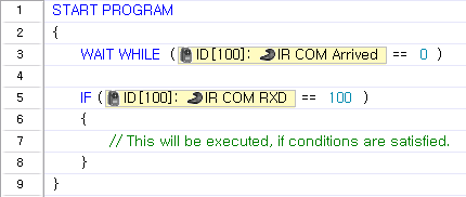
Example
Waits for new data to arrive and executes a block of code when the received data is 100.
IR COM RXD
This parameter is used to read the data received via the wireless communication module.
NOTE : Compatiable Controllers : CM-5, CM-510, CM-700
- The data is a number between 0 and 65535.
- The IR COM Arrived parameter is can be used to check for new data.
- Because there is an input buffer, a maximum of 2 data values can be saved.
- If the input buffer is filled with 2 data values when READ is executed, the first data will be read and removed from the buffer. If there is only 1 data value in the input buffer when READ is executed, the latest data will be retrieved.
Example
Waits for new data to arrive and executes a block of code when the received data is 100.
IR COM TXD
This parameter is used to transmit data via a wireless communication module.
NOTE : Compatiable Controllers : CM-5, CM-510, CM-700
- The data to send must be a number between 0 and 65535.
- When the “Remocon TXD” parameter is set, the data is immediately sent wirelessly.
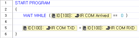
Example
Waits for new data to arrive, and when the data arrives, the received data is transmitted wirelessly.
Object Detection Threshold
This parameter is used to set or read the object detection threshold.
NOTE : Compatiable Controllers : CM-5, CM-510, CM-700
- Set the object detection threshold to be used when determining whether an object is detected or not.
- There is a short-range detection mode and a long-distance detection mode.
- The short range detection mode is activated when the threshold value is set as 0.
Example
The object detection threshold is set as 50, and a block of code will be executed when an object is detected within the threshold.
Light Detection Threshold
This parameter is used to set or read the light detection threshold of the universal sensor (S1).
NOTE : Compatiable Controllers : CM-5, CM-510, CM-700
- Set the threshold to be used when determining whether a light is detected or not.
Example
The light detection threshold is set as 50, and a block of code will be executed when a light is detected within the threshold.
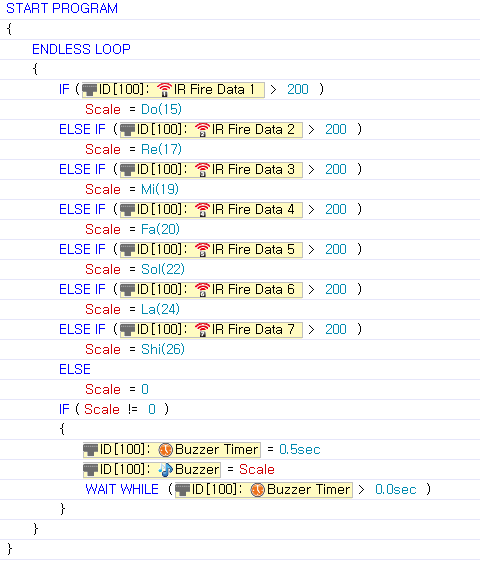
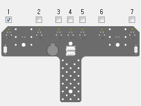
IR Sensor Array
IR Sensor Value
These parameters are used to read the current IR sensor value from the IR Sensor Array.
- The IR array reads values between 1 and 7. The array can be used at distances from 0cm to 5cm.
- Textures and colors from walls and obstacles can influence the output values of the IR array.
- The sensor value is between 0 and 1023.
Example
Detected values can emit different sounds as following the array’s values.
Tip
- Sensor values may be affected by external lights that emit infrared rays, such as sunlight or a fluorescent lamp.
- Sensor values depend on the object’s color and surrounding light, so using the IR sensor to measure the exact distance is not recommended.
- As mentioned above, IR sensor values are different if objects have different colors, even if they are the same distance away. This characteristic can be utilized to distinguish black from white. (Used for tracing lines)
IR Array Buzzer Index
This parameter is used to set or read the musical note played by the buzzer of the ir sensor array
- The “Buzzer Time” parameter must always be used with the “Buzzer Index” parameter. “Buzzer Time” must be set before “Buzzer Index” is set for the correct sound to be played. (This order is very important) (Click here for more information on “Buzzer Time.”)
- Depending on what the “Buzzer Time” is set to, “Buzzer Index” can be set to play a musical note or a melody.
- “Buzzer Time” is set to 255 : Melody Mode
-
Choose from 26 different melodies (0 ~ 25).
- When “Buzzer Time” is between 0 and 254 : Musical Note Mode
-
Choose from 51 notes. The selected note will play for the length set as “Buzzer Time.”
Example
Plays melody #3.
Plays Do, Mi, and Sol for 0.3 seconds each.
IR Array Buzzer Time
This parameter is used to set or read how long the sound is played by the buzzer of the ir sensor array.
- “Buzzer Time” parameter must always be used with the “Buzzer Index” parameter. “Buzzer Time” must be set before “Buzzer Index” is set for the correct sound to be played. (The order is important.) (Click here for more information on “Buzzer Time.”.)
- “Buzzer Time” can be set using buzzer time constants.
- “Buzzer Time” can be set to a value between 0 and 255.
- Each value represents 0.1 second. For example, when “Buzzer Time” is set to 1, the note will be played for 0.1 second. The maximum length a note will be played is 5 seconds. Therefore, when values between 50 and 254 are entered, the note will be played for 5 seconds.
- When “Buzzer Time” is set to 255 : Melody Mode
- Choose from 26 different melodies (0-25).
-
When the melody finishes playing, “Buzzer Time” is reset to 0.
- “Buzzer Time” is between 0 and 254 : Musical Note Mode
- Choose from 51 notes. The selected note will play for the length set as “Buzzer Time.”
-
When it is set to 254, the sound will play without end.
Example
Plays melody #3.
Plays Do, Mi, and Sol for 0.3 seconds each.
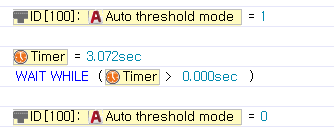
Auto Threshold Mode
Parameters for set black values and automatic detection start/set.
- Starts when transitioning from ‘0’ to ‘1’ then sets after transitioning from ‘1’ to ‘0’
- Also sets the timer from start to set.
Example
During a ‘1’ the LED will turn on, detecting a white or black then the array automatically sets values.
IR Obstacle Detected
Paramenters to determine IR array obstacle values
- In the IR array if each IR sensor detected black value is lower than the set black valuethe values will be assigned as shown below; the LED turns on.
| Binary value | Decimal Value | Black Detection |
|---|---|---|
| 0000001 | 1 | Black detection for IR sensor #1 |
| 0000010 | 2 | Black detection for IR sensor #2 |
| 0000100 | 4 | Black detection for IR sensor #3 |
| 0001000 | 8 | Black detection for IR sensor #4 |
| 0010000 | 16 | Black detection for IR sensor #5 |
| 0100000 | 32 | Black detection for IR sensor #6 |
| 1000000 | 64 | Black detection for IR sensor #7 |
-
From the diagram you may check binary values.
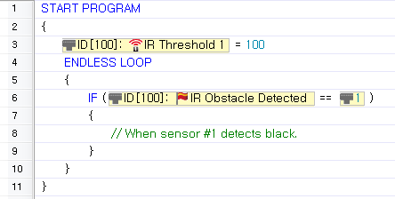
Example
Set sensor #1 to 100; when sensor #1 detects black do a specified action.
IR Threshold
Reference black/white for the IR array
- Determines white/black set values.
- sensor and set black values
| Black Detection | LED | |
|---|---|---|
| Sensor value <= set value | BIT 1 | ON |
| Sensor value > set value | BIT 0 | OFF |
Example
Set sensor #1 to 100; when sensor #1 detects black do a specified action.

Direct Access
The address of peripheral devices such as DYNAMIXEL’s can be accessed directly and read from or written to.
NOTE : Compatiable Controllers : CM-5, CM-510, CM-700
- Data can be read from or written to a specific in the form of bytes or words.
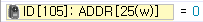
Example
Write 0 at word address 25 of DYNAMIXEL with ID 105.
Print the value stored in the word address 25 of DYNAMIXEL with ID 105.

Variables
This is a storage place inside a program capable of saving, editing, and reading data.
- If a variable with the same name already exists, it is not created. Instead, the existing varible is used.
- Spaces are not permitted in variable names.
- Variable names cannot start with a number.
- Special characters (!, @, #, $, etc ) are not allowed in variable names.(Underscores ( _ ) are permitted.)
Example
Variables may be used for many purposes. Existing Variables are listed in the “Set Device or Number” window.
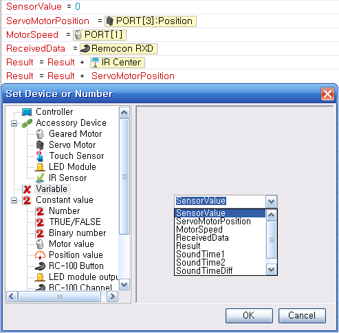
Tip
Variables are useful when a number to be remembered, when a value must be changed depending on the situation, or when multiple values must be changed at once.