
Edit on GitHub
Gyro Sensor(GS-12)
New Sensor
Introduction
- Measures angular velocity.
- Calculates which side the robot is tilted or is getting more power.
- Maintains the robot’s balance and can be used for other movement applications.
Compatibility Guide Controller Compatibility
Specifications
- Weight : 2.8g
- Size : 23mm x 23mm x 10mm
- Working Temperature : -40°C ~ 85°C
- Angular Velocity Calculation Range : -300°/s ~ 300°/s
- Bandwidth : 140Hz
- Sensitivity : 3.33mV/dps
- Recommended Voltage Supply : 4.5 ~ 5.5 V
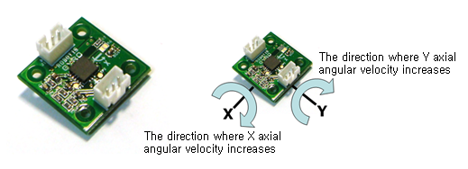
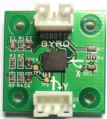
Pinout
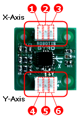
- X Axis Pin
- ADC : Outputs the angular velocity into analog signals.
- GND
- VCC ( 5V )
- Y Axis Pin
- VCC ( 5V )
- GND
- ADC : Outputs the angular velocity value into analog signals.
Sensor Output
New Sensor
| Item | MAX | ~ | MIN |
|---|---|---|---|
| Output Value | 510 | 300 | 100 |
| Angular Velocity | +300°/s | 0°/s | -300°/s |
| Voltage | 2.5 V | 1.5V | 0.5V |
Standard VCC Voltage Value is 5V.
Old Sensor
| Item | MAX | ~ | MIN |
|---|---|---|---|
| Output Value | 455 | 250 | 45 |
| Angular Velocity | +300°/s | 0°/s | -300°/s |
| Voltage | 2.23 V | 1.23V | 0.23V |
Standard VCC Voltage Value is 5V.
- When the angular velocity is 0 (when still), the output value is approximately 250. When it suddenly turns to one axis, the max value output is 455 and the minimum 45, showing a 300°/s angular velocity. Here the mark or sign represents direction.
- Depending on the temperature, there may be 1% difference.
- There may be a difference in value depending on the standard VCC voltage value and circuit noise. Thus, we recommend to average several values before use.(When sampling, the robot must not be moving.)
-
You can READ the value using the User’s Device Parameter in RoboPlus Task.
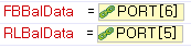
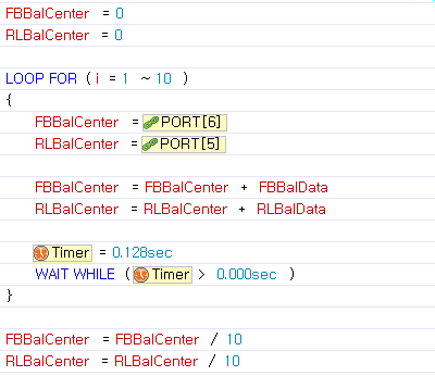
-
You may sample it out like below. It reads 10 values per 0.1 sec and makes an average. This value can be used as the standard value.
Tutorials
- RoboPlus Task : Please refer to User’s Device Parameter section in the Roboplus Task.