Introduction
Software Download
Windows
Linux
Mac
DYNAMIXEL Wizard 2.0
DYNAMIXEL Wizard 2.0 is an optimized tool for managing DYNAMIXEL from various operating systems. The following features are provided with DYNAMIXEL Wizard 2.0.
- DYNAMIXEL Firmware Update
- DYNAMIXEL Diagnosis
- DYNAMIXEL Configuration and Test
- DYNAMIXEL Data Plotting in Real-Time
- Generate & Monitor DYNAMIXEL Packets
Supported Protocols
- Protocol 1.0
- Protocol 2.0
- Modbus-RTU (DYNAMIXEL-P series only)
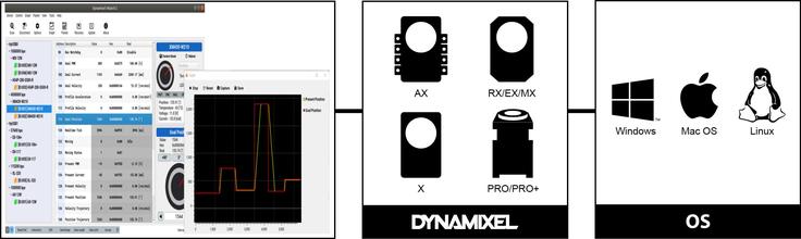
NOTE: Compatibility Table
Supported OS
- Windows 7 / 8.1 / 10 (32 bit and 64 bit)
- Linux
- Ubuntu 18.04 (64 bit)
- Ubuntu 16.04 (64 bit)
- MacOS 10.12 / 10.13 / 10.14 (64bit)
WARNING:
- DYNAMIXEL Wizard 2.0 is tested with a desktop and laptop only.
- Only x86 architectures support DYNAMIXEL Wizard 2.0.
Definition of Firmware
Firmware is a fundamental program to operate the hardware device. It is recommended to keep the firmware updated because it contains various communication regulations to exchange data with other devices such as computers or smartphones. Although almost all ROBOTIS products are shipped with installed firmwares, new firmwares can be released for updated features or bug fixes.
Importance of Firmware Update
- The new firmware may contain newly developed or updated features.
- The new firmware can be released to support software compatibility.
- The new firmware can be released to fix bugs.
- Updating the latest firmware may resolve functional issues.
Supported Products
Software Installation
Install: Windows
- Download the package file.
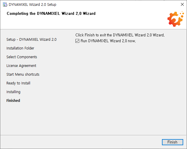
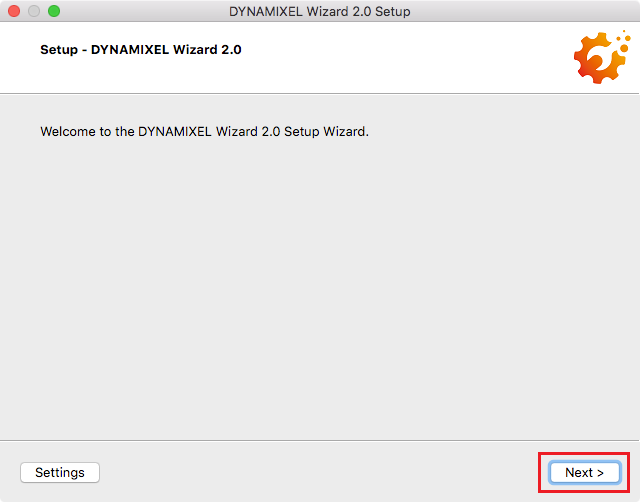
- Execute downloaded installation file.
-
Click on
Nextbutton to proceed installation.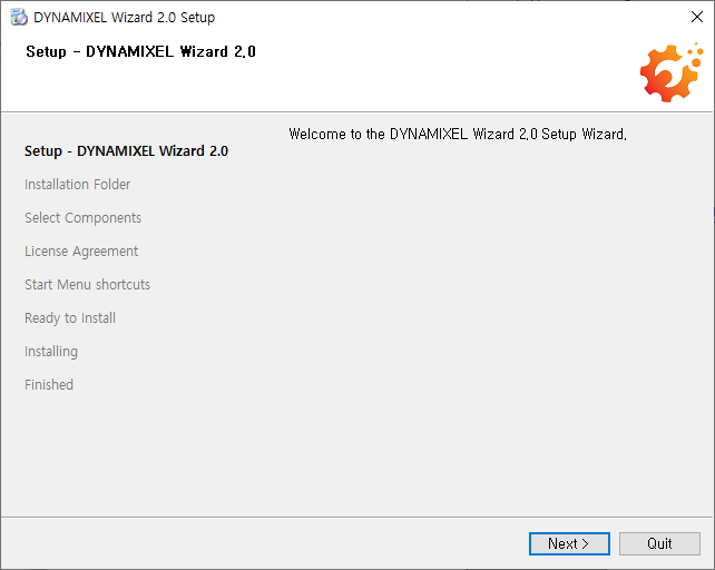
Install: Linux
- Download the package file.
-
Enter the following command to change the permission.
$ sudo chmod 775 DynamixelWizard2Setup_x64 -
Run the install program.
$ ./DynamixelWizard2Setup_x64 -
Click on
Nextbutton to proceed installation. - After completing the installation, please add account id to dialout group in order to access the USB port. Replace the
in the command below to your actual user id. $ sudo usermod -aG dialout <your_account_id> - Reboot in order the changes to be effective.
$ reboot
Install: Mac
NOTE: Modern Mac OS supports app store installation only.
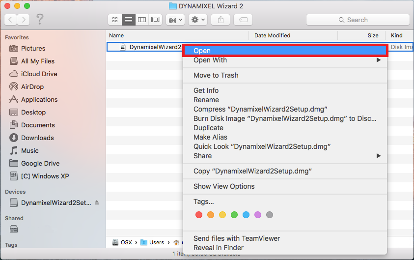
- Download the package file.
- Right click on the downloaded dmg file and select
Openfrom the mene.
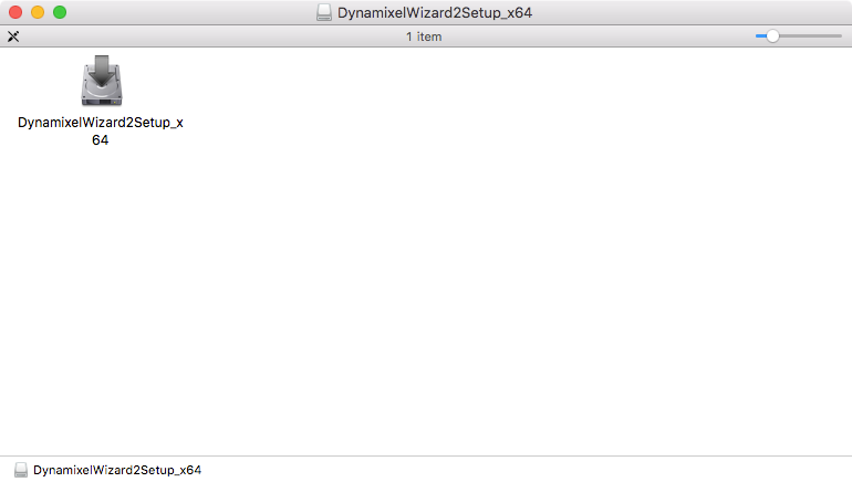
- Launch the
DynamixelWizard2Setup_x64file.
- If a warning message pops up, select
Opento proceed installation.
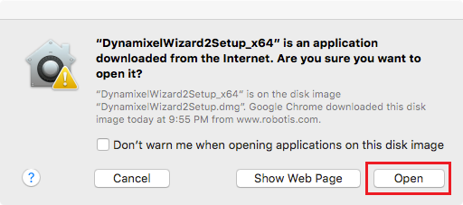
- Click
Nextto continue and follow the setup instruction.
Uninstall Software
Uninstall: Windows
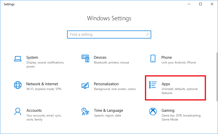
-
From Windows Settings, select Apps.
-
In the Apps & features tab, find
Dynamixel Wizard 2and selectUninstall.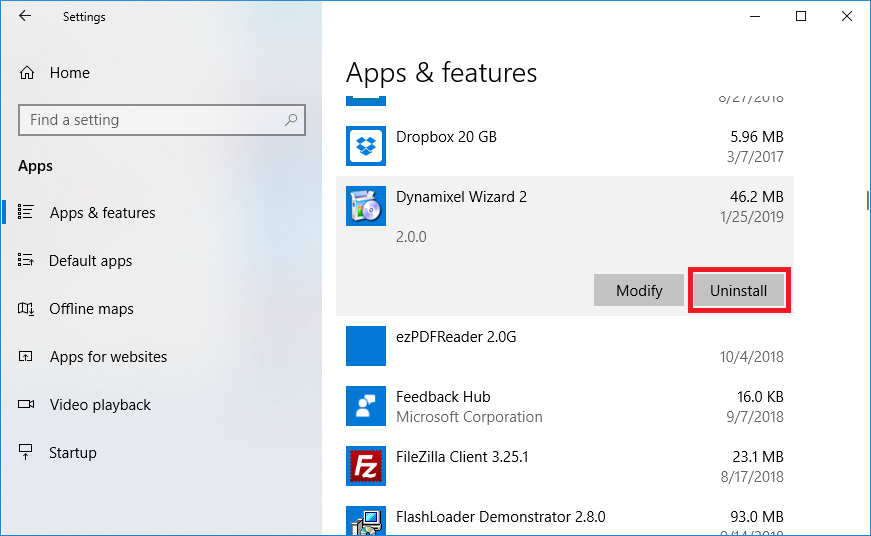
-
Select
Remove all componentsand proceed by clickingNextbutton.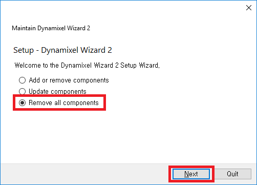
Uninstall: Linux
-
From the folder where DYNAMIXEL Wizard is installed, execute
maintenancetool. -
Select
Remove all componentsand clickNextto proceed.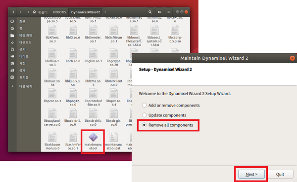
Uninstall: Mac
- Go to
DYNAMIXEL2WizardfromApplications. - Execute
maintenancetoolin DYNAMIXEL2Wizard folder. - Select
Remove all componentsand clickNextto proceed.
Menu Description
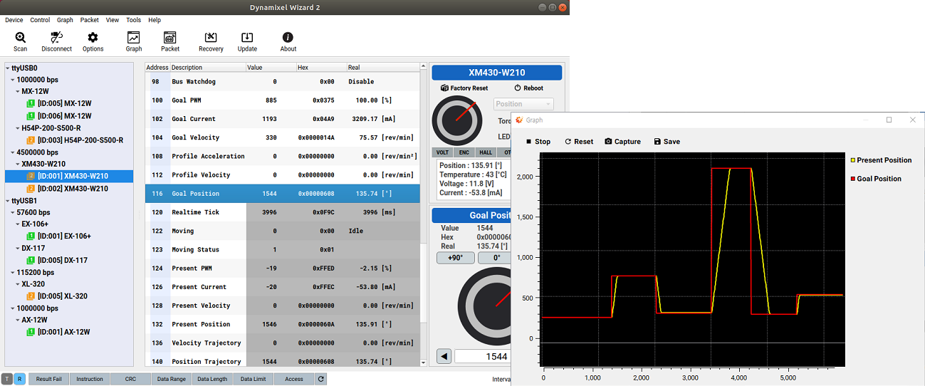
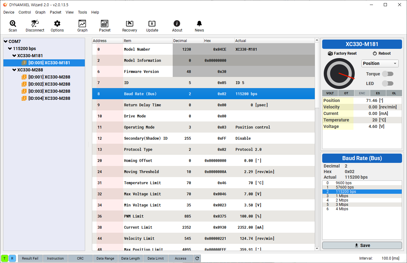
Main Screen
The main screen of software classifies the detected DYNAMIXEL’s according to communication ports, baudrates, and products. Detected DYNAMIXEL’s can be tested by modifying control table values.
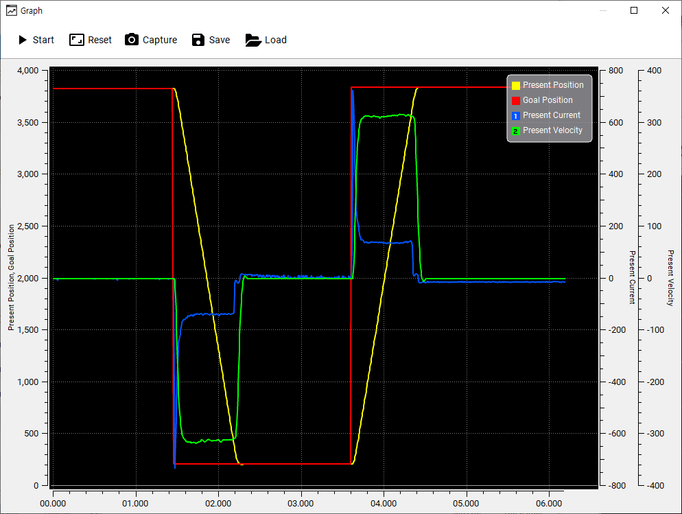
Graph Window
By selecting control table items to be plotted, values of the selected items will be drawn in the graph window in real time. Please refer to Basic Features > Graph section for more details about selecting control table items.
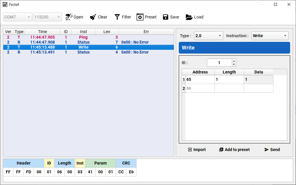
Packet Window
User can manually generate an Instruction packet for the selected protocol version. Detailed packet data can be loaded by selecting a packet in the packet history.
Basic Features
Connect DYNAMIXEL
DYNAMIXEL Scan Options
-
Go to
Tools>Optionsor use shortcut keyF4.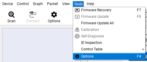
-
Select
Scanfrom the left column menu to display scan options.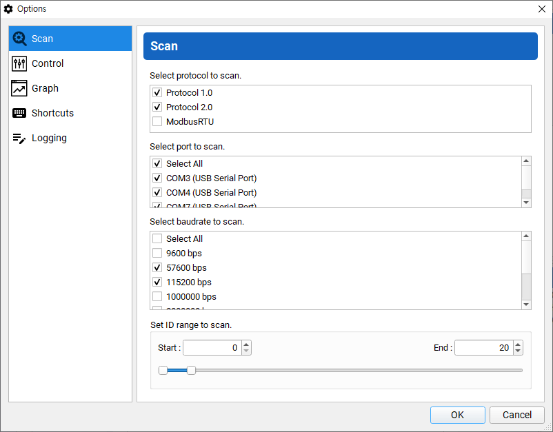
-
Select Protocol Type, communication ports, baudrates, and the range of ID to scan. Click
OKto confirm the selection. Selecting less option reduces time to scan DYNAMIXEL.
Scan DYNAMIXEL
-
Go to
Device>Scanto start searching connected DYNAMIXEL’s.NOTE : If Open failed is shown up, please check whether communication port is connected at the Main Toolbar or not, then button
Disconnectto avoid port collision.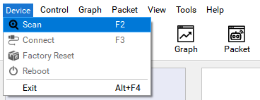
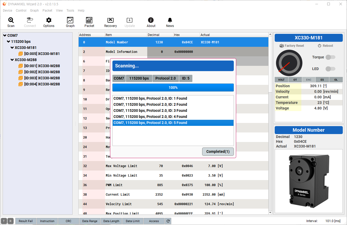
-
Detected DYNAMIXEL’s are listed on the left column.
DYNAMIXEL Control Table
-
Once the
Scanis complete, detected model of DYNAMIXEL will be shown at the device list on the left side pannel. -
Detected DYNAMIXEL’s are classified according to communication ports, baudrates, and products. Select a group or device to run the test.

-
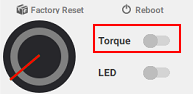
Factory Resetbutton in the Sub Menu on the right column will reset DYNAMIXEL to factory status(ID and Baudrate will not be reset).
Rebootbutton will soft reset DYNAMIXEL.
Torqueswitch will toggle the Torque of DYNAMIXEL.
LEDswitch will toggle the LED of DYNAMIXEL.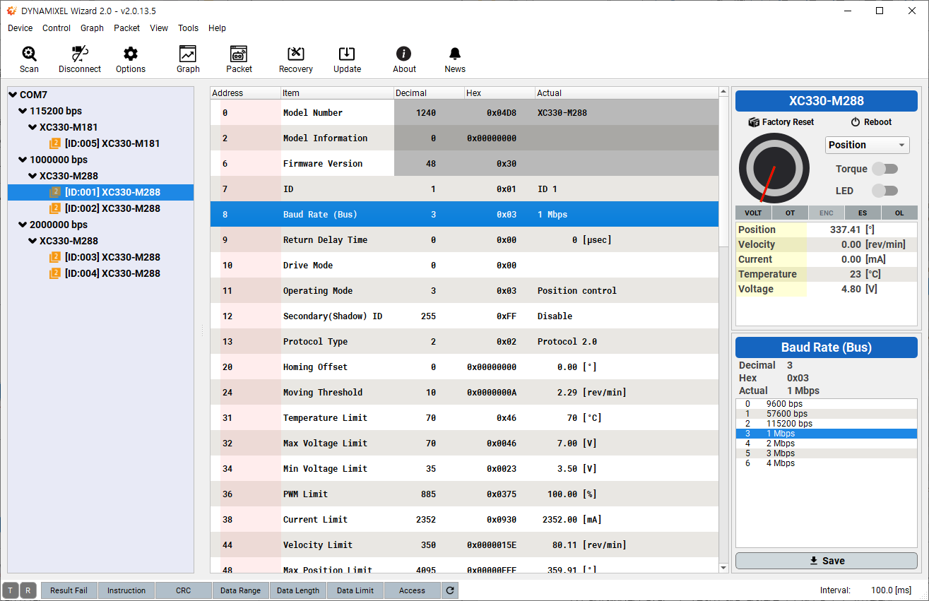
-
Click the
Torquebutton to enable DYNAMIXEL Torque.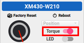
-
Select
Goal PositionorGoal Velocityitem in the control table in the middle column.NOTE: Read the control table of your DYNAMIXEL as the item can be different depending on the model and Operating Mode of the DYNAMIXEL.
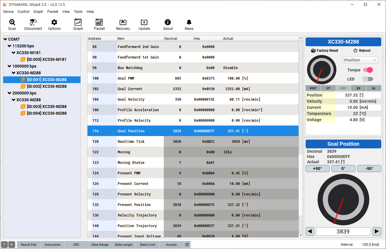
-
Position controlling interface will appear on the buttom right corner of the program.
WARNING : Please be cautious when changing values as DYNAMIXEL can rotate or move.

- When selecting
Position controlfrom Operation Mode, you can use a virtual dial controller - Control a horn of DYNAMIXEL by using the controller.
- Input values into the input window.
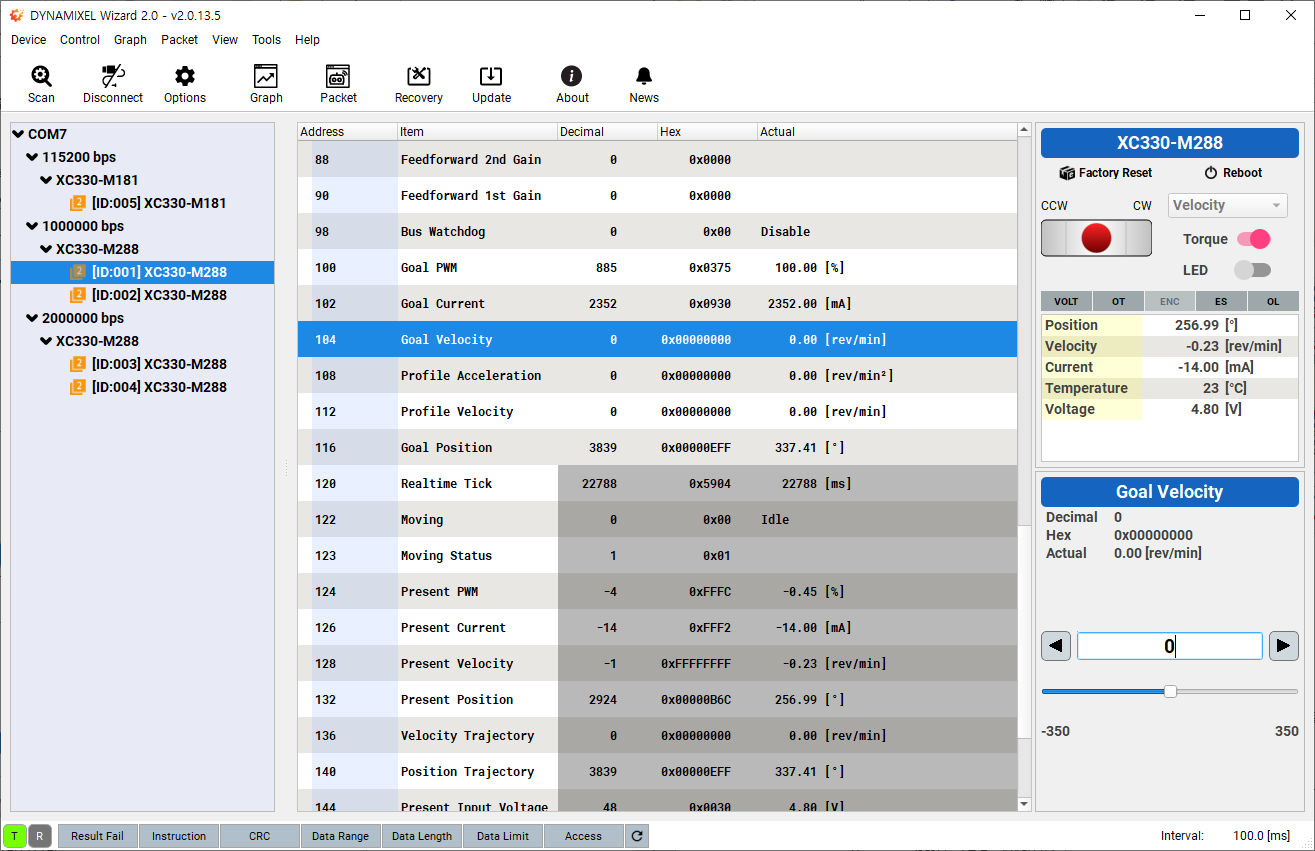
- When selecting
Velocity control/Current control/PWM controlfrom Operation Mode, you can use a virtual joypad. - Move a horn to CW / CCW by using the controller.
- Input values into the input window to increase (or decrease) the speed of a horn of DYNAMIXEL.
- More information on the virtual controller is available at Modifying Control Value
- When selecting
-
Communication Statuson the buttom left corner represents communication status between PC and DYNAMIXEL’s. -
The
Packet Statussection indicates the status of response packet from DYNAMIXEL. -
The
Hardware Alarmsection in the Device Status indicates hardware error status of DYNAMIXEL. -
Please refer to e-Manual of each product for more information regarding the Control Table.
-
Below options in the Control Table allow items to be grouped or ungrouped.
- Group : Selected items can be grouped and folded or unfolded.
- Ungroup : Ungroup the selected group.
Graph
Graph Options
-
Go to
Tools>Options -
Select
Graphfrom the left column menu to display scan options.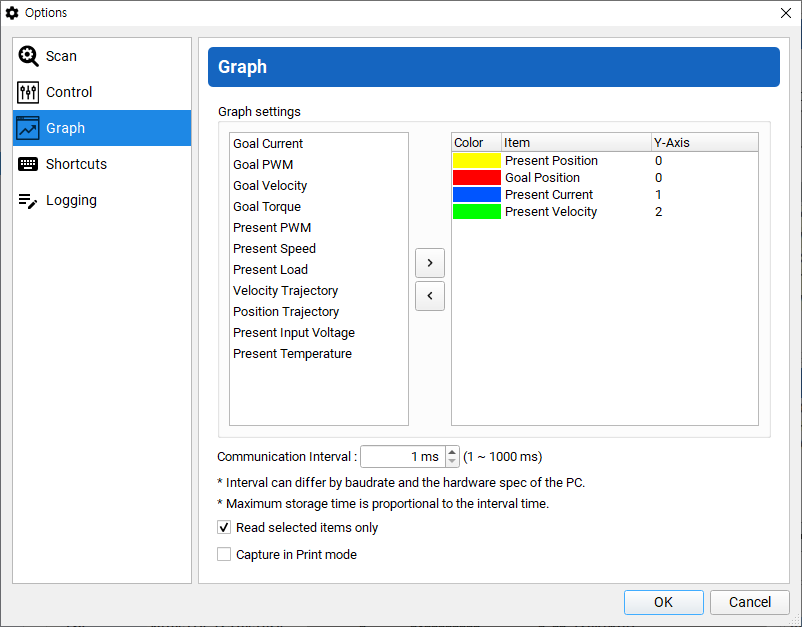
-
Click
>button to add item. (<can remove item)
-
Double-click an item, to call
Read Item Settingsbox.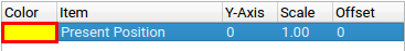
-
Read Item Settingscustomizes a line color with Y axis number.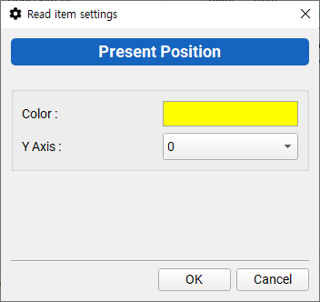
NOTE:
ScaleandOffsetare no longer appearing at the option box above, from the latest version of software. Adjust these factors at the Graph Window in real time. (See the additional explanation at Y-Axis below)-
Y-Axis: it adds Y-axis to a selected item. The Maximum is 10.
Scale: Adjust scale of axis at the Graph Window (Main Axsis, Secondary Axis) using a mouse wheel.Offset: Adjust Offset by dragging the desired axis up and down at the Graph Window (Main Axsis, Secondary Axis).
-
-
Communication interval can be set between 1 ~ 1000ms. Smaller interval will display refined graph.
NOTE : The actual communication interval can differ by baudrate and the hardware spec of the PC.
-
In order to optimize the graph drawing speed, check the option to read selected items only.
NOTE : Checking this option will only refresh selected items in the Control Table.
-
Printing Mode captures your graph with white background.
-
Click
OKto confirm changes.
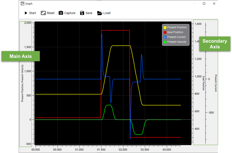
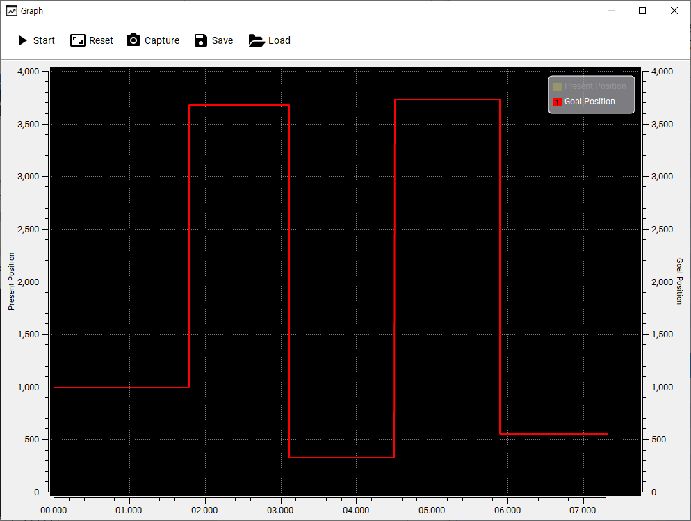
Start Plotting
-
Go to
View>Graphto display the graph window.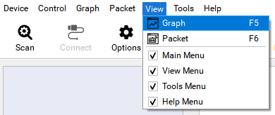
-
Click
Startbutton in the graph window to start plotting data.WARNING : If there isn’t any detected or connected device,
Startbutton will be disabled. Please scan DYNAMIXEL first.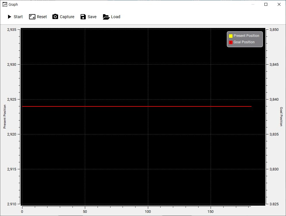
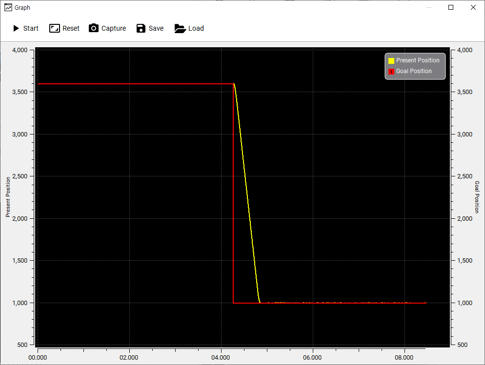
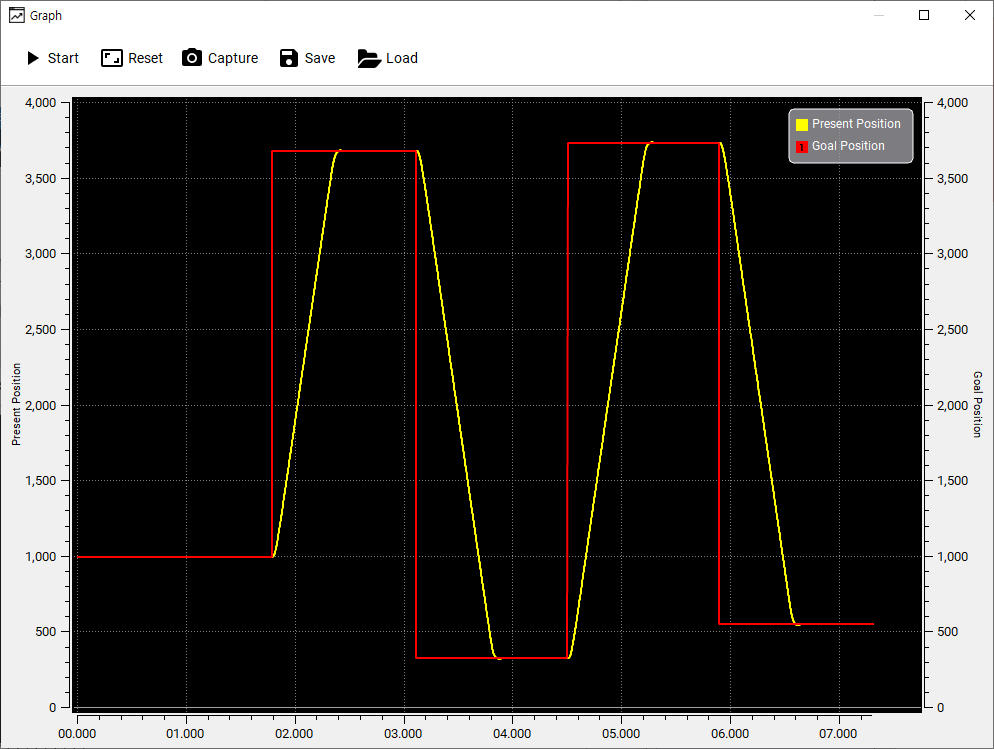
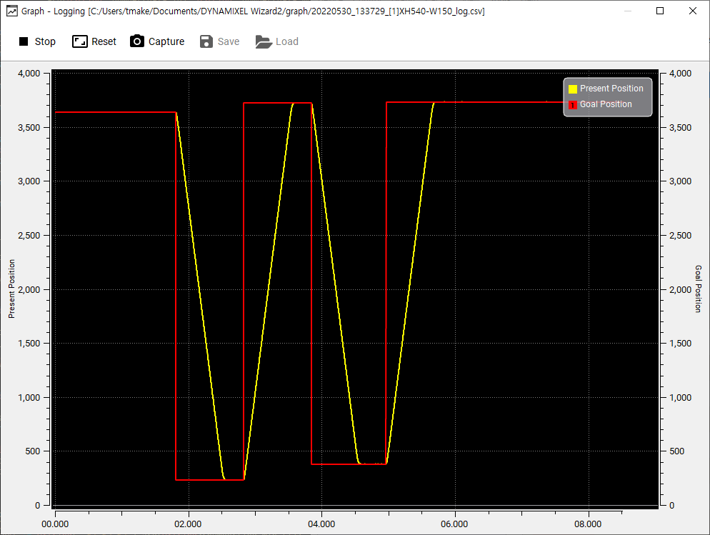
-
After start plotting, enable Torque first then change
Goal Positionto see howPresent Positiondata is plotted in real time.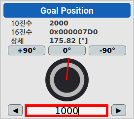
-
Disable the plotting graph by clicking the certain item on the right side of the graph window.
-
Use the features to control graph window.
- Start/Stop : Start/Stop plotting
- Reset : Reset zoom level
- Capture : Save current graph window to an image file
- Save : Save plotted data to CSV file
- Load : Load CSV file
- Enable/Disable Item : Click items on the right to toggle visibility
- Zoom : Drag an area to zoom
Shift+Select Area: Zoom In on X axis onlyCtrl+Select Area: Zoom In on Y axis onlyCtrl+Mouse Wheel: Zoom In / Out.
- While running the graph, use
Shift+Mouse Wheelto adjust X axis length from 1 to 10 seconds.
Packet
-
Go to
View>Packetto display the packet window.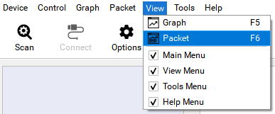
-
Set the communication port and baudrate then click
Opento open the port. Once the port is successfully opened, DYNAMIXEL protocol minitoring on the port will begin.NOTE : If Open failed is shown up, please check whether communication port is connected at the Main Toolbar or not, then button
Disconnectto avoid port collision.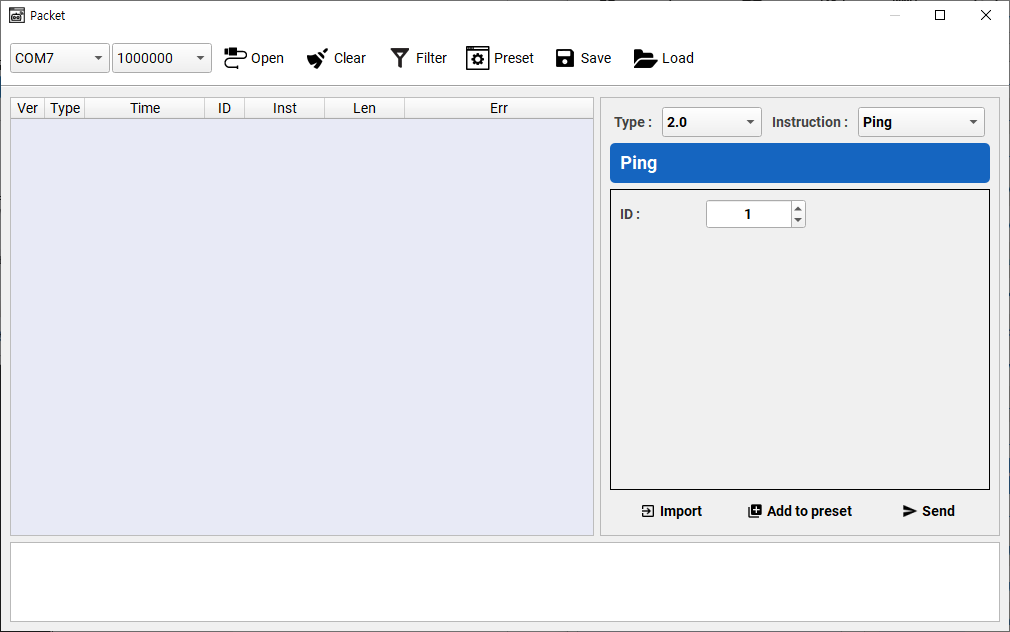
-
Select Protocol Type and instruction to use. In this example,
Writeinstruction for Protocol Type2.0is selected.NOTE : Protocol Type can be different depending on a model of DYNAMIXEL. Confirm Protocol Type of your DYNAMIXEL.

-
Specific data can be written on the instuction as shown below. In this example, LED will be turned on by writing
1to LED control address.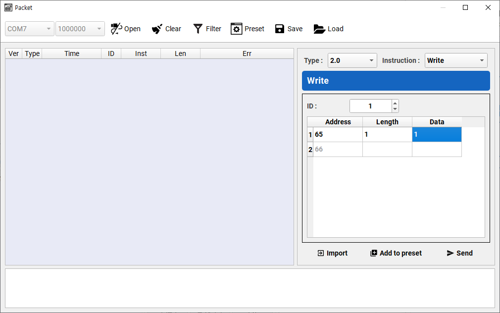
- Control Table address of LED : 65
- Length of the LED data[Byte] : 1
- Value to turn on the LED : 1
-
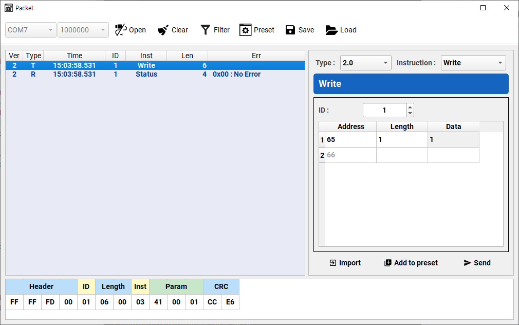
Assembled packet can be found at
Packet Detailssection in the bottom of packet window.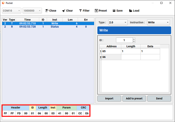
-
Transmit the assembled packet with
Sendbutton.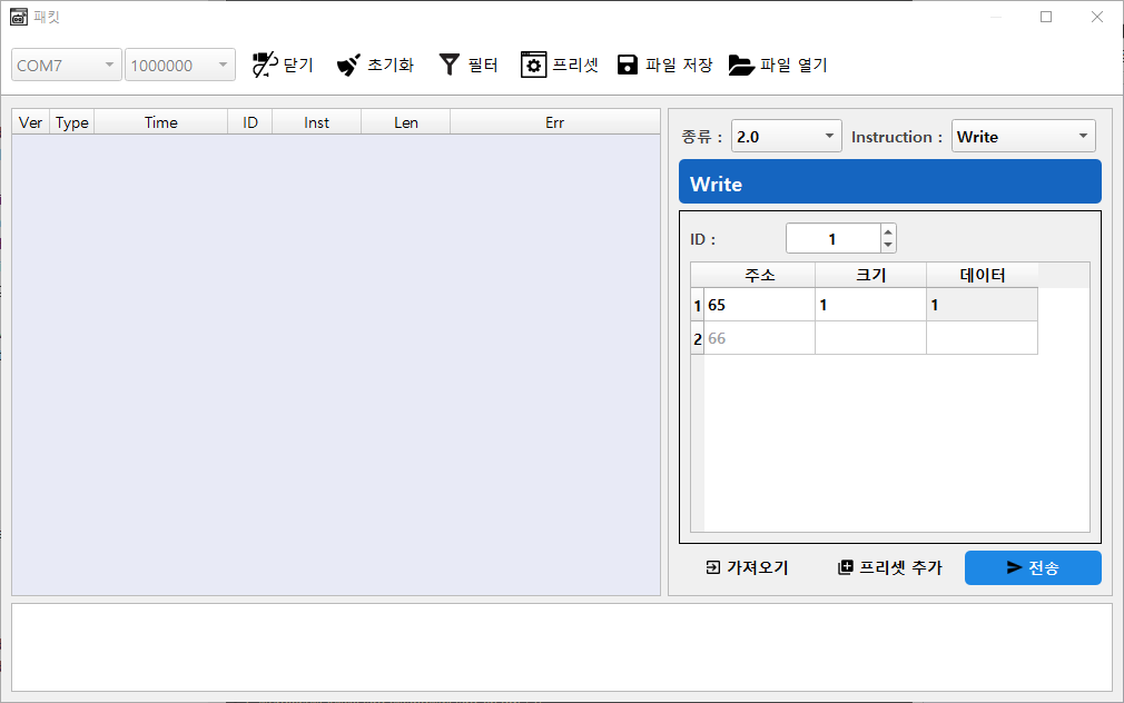
-
Clicking the sent packet shows the detailed packet information.
Firmware Update
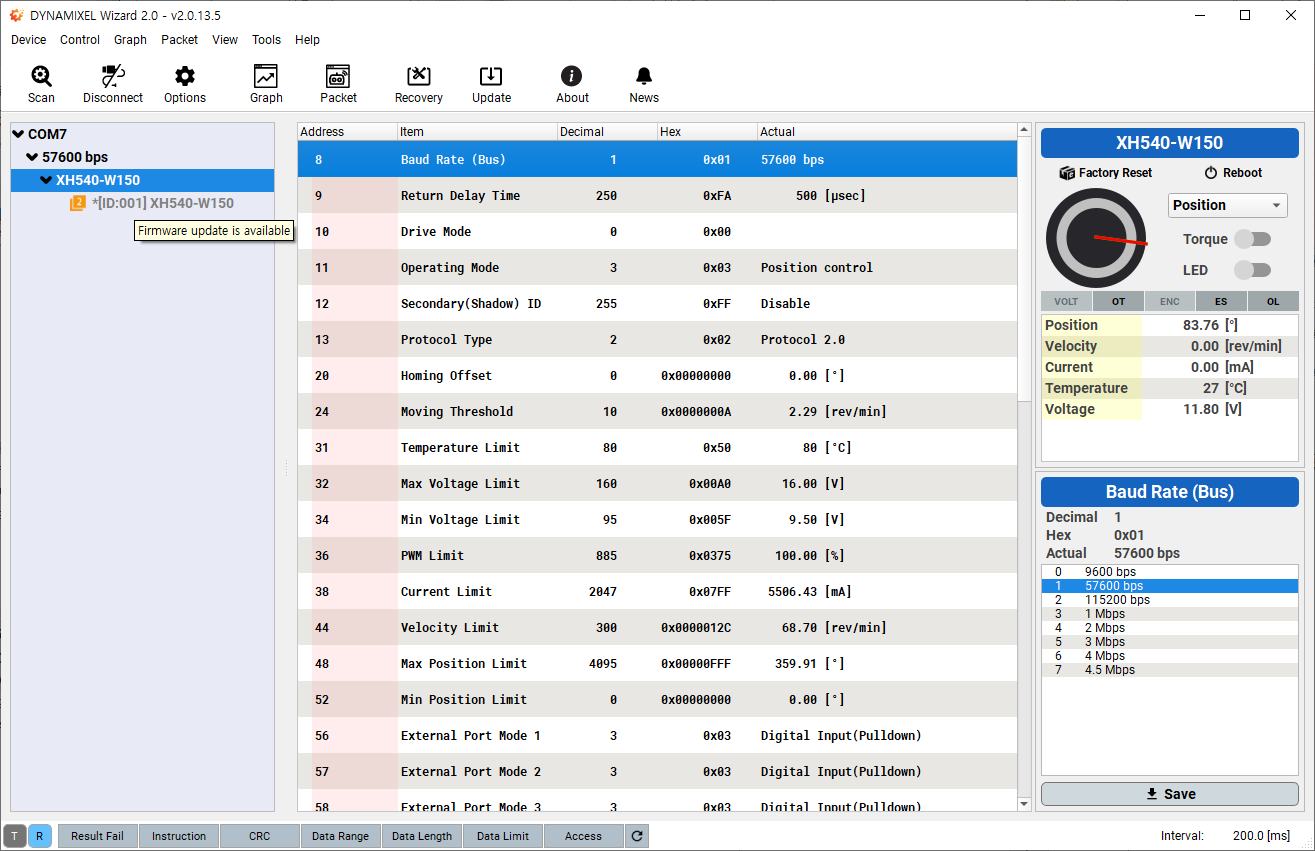
When your connected DYNAMIXEL has a firmware update available an asterisk (*) will be displayed next to the model name on the device list.
When positioning your mouse cursor over the model name, Firmware update is Available will also be displayed as a tooltip.
-
Go to
Tools>Firmware UpdateNOTE : If no DYNAMIXELS are detected, the
Firmware Updateoption will not be available.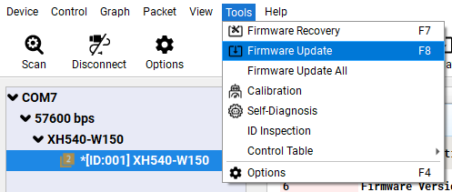
-
Firmware update will begin with a brief instruction. Please do NOT disconnect or turn off DYNAMIXEL.

-
Click
Nextto begin firmware update. Be careful not to disconnect or turn off DYNAMIXEL.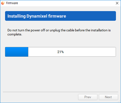
-
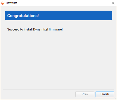
Confirm the firmware update result.
Firmware Update All
-
Go to
Tools>Firmware Update All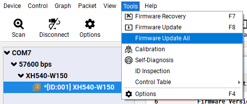
-
Select all or desired DYNAMIXEL’s, then click
Nextbutton.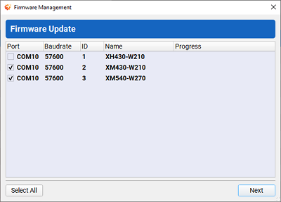
-
Firmware of selected DYNAMIXEL’s are updated.
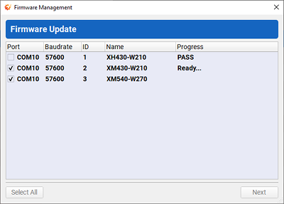
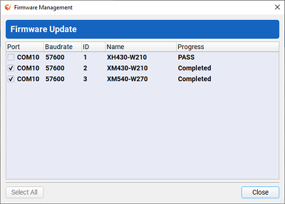
-
Wait until update is completed for all DYNAMIXEL.
Firmware Recovery
-
Go to
Tools>Firmware Recovery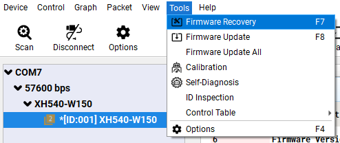
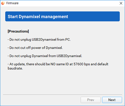
-
Firmware recovery will begin with a brief instruction. Please do NOT disconnect or turn off DYNAMIXEL.
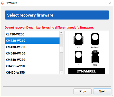
-
During the firmware recovery mode, DYNAMIXEL Wizard 2.0 cannot identify the model information of DYNAMIXEL, so correct model has to be selected manually. Selecting wrong model can cause malfunction or serious hardware damage.
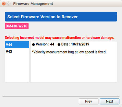
-
Select a desired firmware version.
-
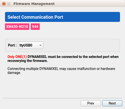
The proper communication port that is connected to DYNAMIXEL has to be selected manually. If the port is in use, it has to be released first.
WARNING : Only one DYNAMIXEL should be connected to the port when recoverying DYNAMIXEL firmware.
-
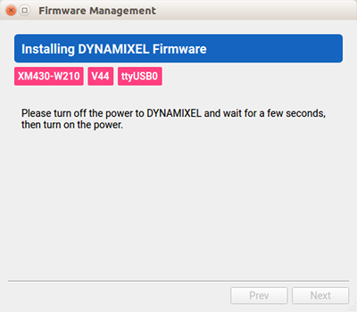
Toggle the power of DYNAMIXEL to be detected from DYNAMIXEL Wizard 2.0.
-
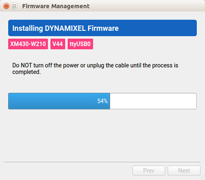
If DYNAMIXEL is successfully detected, wizard begins firmware recovery. Please do NOT disconnect or turn off DYNAMIXEL.
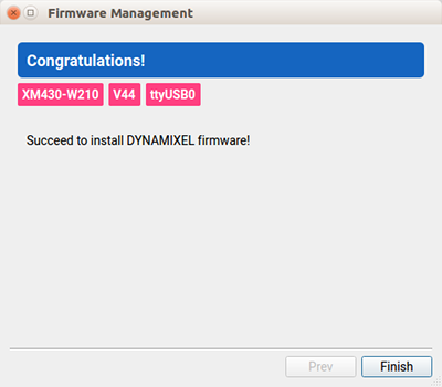
-
Confirm the firmware recovery result.
Advanced Features
ID Inspection
DYNAMIXEL Tips | Use ID Inspector to Change Overlapping IDs with Ease
As the DYNAMIXEL can be distinguished by its own ID in packet communication with your main controller, the ID assigned on DYNAMIXEL has to be unique.
If there are overlapping ID in your application, communication between the main controller and DYNAMIXELs or scanning DYANMIXEL via DYNAMIXEL Wizard 2.0 will be failed.
The ID Inspection resolves the overlapping ID although they remain wired. For more details, watch a tutorial video above or read through the following instructions.
Supported DYNAMIXEL
- DYNAMIXEL-X (Firmware v45 or above, For X330 Series: Firmware v46 or above)
- DYNAMIXEL-P (Firmware v12 or above)
- XL-320 is not supported
-
Go to
Tool>ID Inspection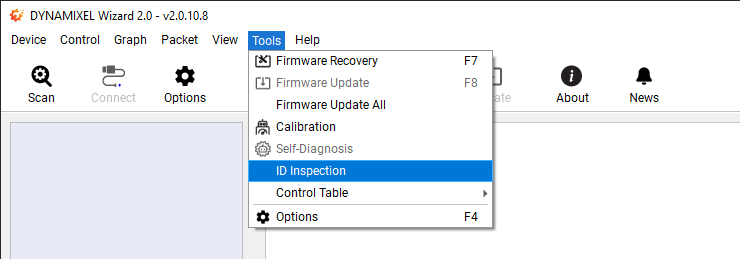
-
Select your right USB port and Baud rates, and click on
Scan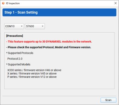
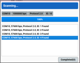
-
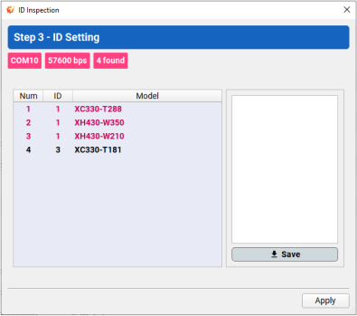
Once DYNAMIXEL scan is started, state of scanning DYNAMIXEL is displayed.
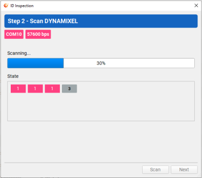
Note: Perform Firmware Recovery if you fail to scan any DYNAMIXEL.
-
Click on
Nextfor “ID Setting”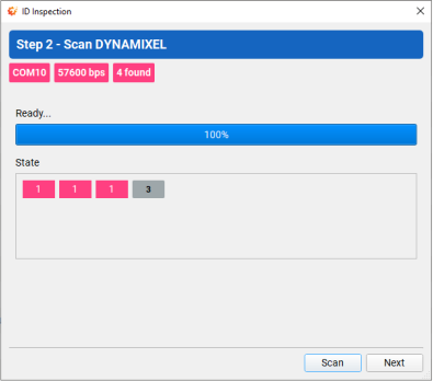
-
Select an item (colored red) and assign new ID from the right box to resolve ID overlapping.
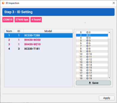
Note : If you select any item in the list, the DYNAMIXEL will blink once.
-
If new ID are saved to the items of DYNAMIXEL, it will be colored green. Once completed, click on
Apply.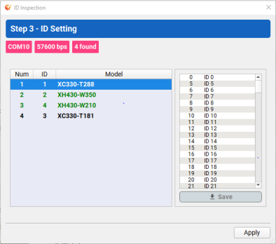
-
Click on
Finishto exit theID Inspectionwindow.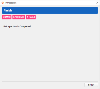
-
Confirm the DYNAMIXEL Wizard 2.0 scans DYNAMIXELs successfully.
Backup and Restore
DYNAMIXEL Tips | EEPROM and RAM Data Restoring Using Backup Funcion
Data in both EEPROM and RAM (Specific items only) can be stored inside DYNAMIXEL using Backup function.
This can be useful if the DYNAMIXEL are reset after the Firmware Recovery or any situation in data reset.
The stored data by backup can be restored in using Restore EEPROM.
See the available items in Control Table for data backup,
- All Data in EEPROM
- Velocity P.I Gains
- Position P.I.D Gains
- Feedforward 1st & 2nd Gains
- Profile Acceleration
- Profile Velocity
- Indirect Addresses (Except DYNAMIXEL-P Series)
Note: Be sure to set the Restore RAM bit of the Startup Configuration(60) address in order to restore the RAM data on startup.
Supported DYNAMIXEL
- DYNAMIXEL-X (Firmware v45 or above, For X330 Series: Firmware v46 or above)
- DYNAMIXEL-P (Firmware v12 or above)
- XL-320 is not supported
Control Table Backup
-
Connect and Scan DYNAMIXEL.
-
Make sure to turn off the Torque of DYNAMIXEL. Otherwise, backup will fail.
-
Select
Tool>Control Table>Backup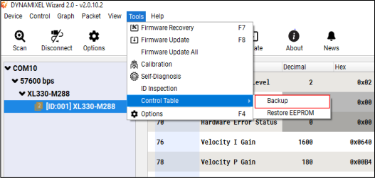
-
Check if the
Backup Ready(147)address is set to1after backup.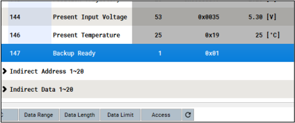
Restoring EEPROM Area
-
Go to
Tool>Control Table>Restore EEPROM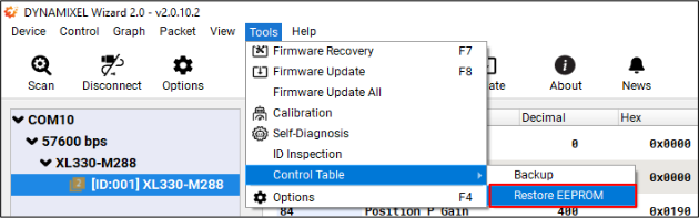
-
DYNAMIXEL will be rebooted and restore the EEPROM settings.
Restoring RAM Area
-
Set the Restore RAM bit of the
Startup Configurationas below.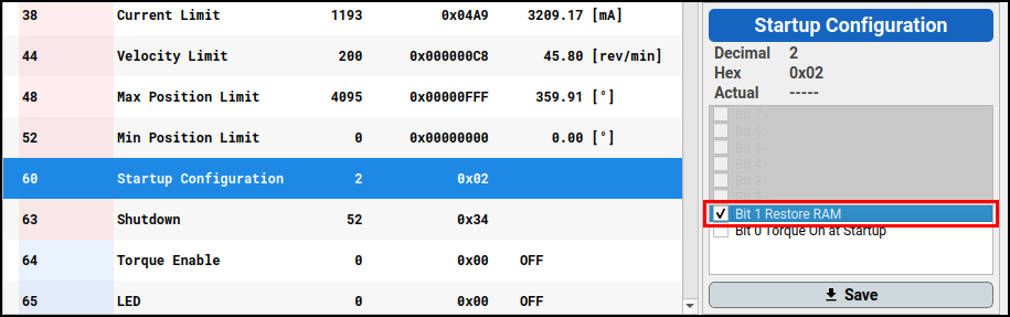
-
The data in specific RAM area(listed below) will be restored when DYNAMIXEL is rebooted.
- Velocity P.I Gains
- Position P.I.D Gains
- Feedforward 1st & 2nd Gains
- Profile Acceleration
- Profile Velocity
- Indirect Addresses (Except for DYNAMIXEL-P Series)
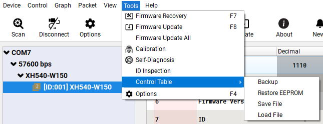
Save and Load Backup File
Save and Load backup data of EEPROM field as .ctd file. Utilizing “Save and Load Backup File” reduces the consuming time tasks of DYNAMIXEL configuration, and lowers the possibility of configuration error.
NOTE: Saved backup file(.cd) can be used between the same DYNAMIXEL models.
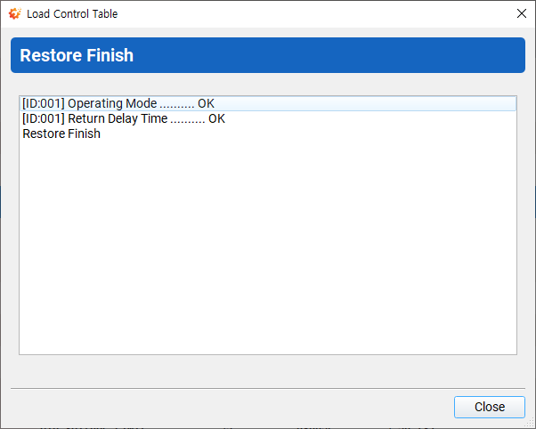
When loading backup data from .ctd file, it provides restoring options to ignore restoring particular data at EEPROM field.
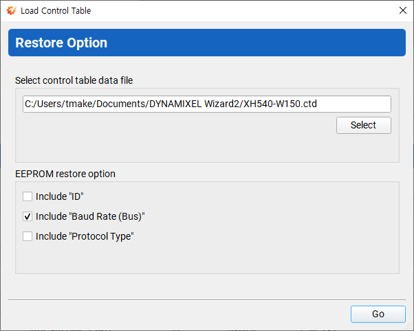
The resulting log shows the restored item.
Modifying Control Values
-
Drag or slide the interface (Moderately changes values)
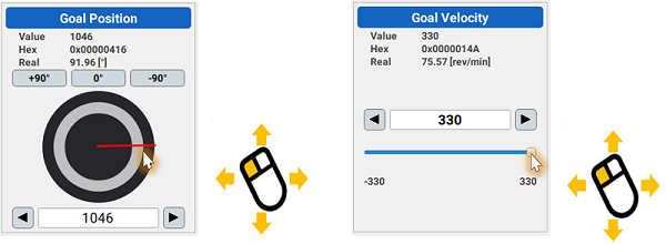
-
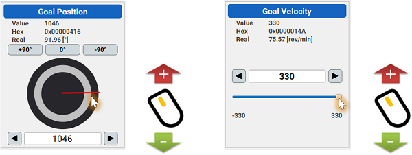
Mouse wheel scroll (Slightly changes value)
-
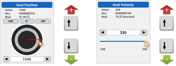
Directional keys (Finely changes value)
-
Enter the value
NOTE : Press
Enterkey to apply the value.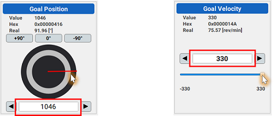
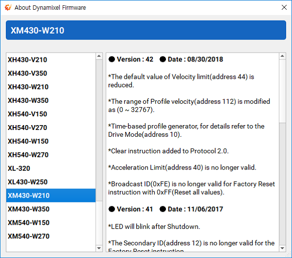
Firmware Information
Firmware version, release date, update note can be found here.
-
Go to
Help>About Dynamixel Firmware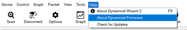
-
Firmware version, release date, update note of the selected DYNAMIXEL can be found.
Calibration
If the horn is misaligned after gear set replacement or reassembly, please perform calibration.
-
Go to
Tool>Calibration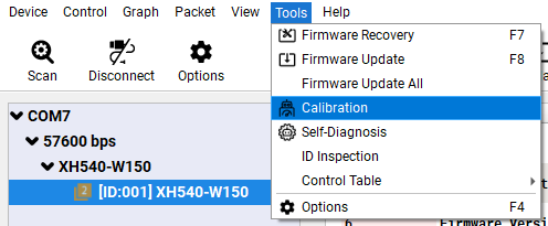
NOTE:
Calibrationitme will be disabled at the menu for non-supported DYNAMIXEL such as AX SeriesWARNING : Only one DYNAMIXEL has to be connected to the port when calibrating DYNAMIXEL.
-
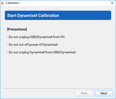
Calibration will begin with a brief instruction.
-
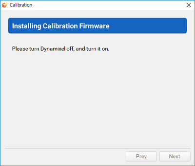
Toggle the power of DYNAMIXEL to be detected from DYNAMIXEL Wizard 2.0.
-
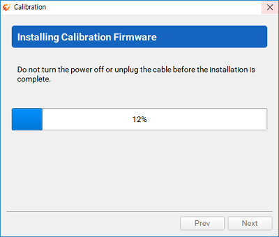
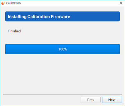
If DYNAMIXEL is successfully detected, calibration firmware will start being installed. Please do NOT disconnect or turn off DYNAMIXEL.
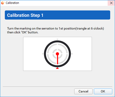
-
Calibrate the first position.
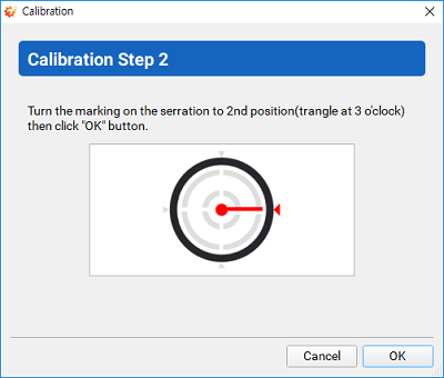
-
Calibrate the second position.
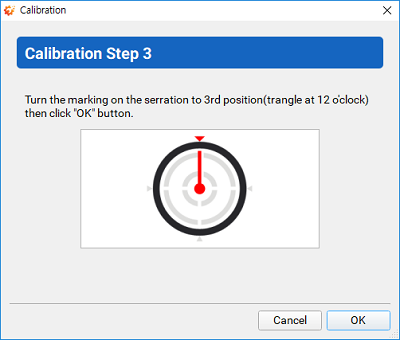
-
Calibrate the third position.
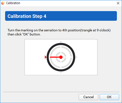
-
Calibrate the fourth position.
-
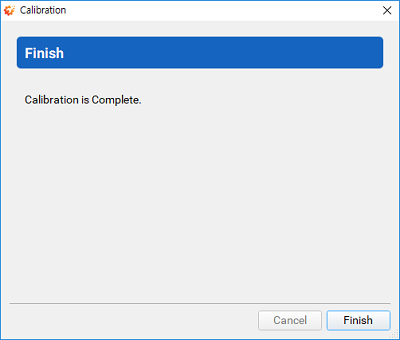
Clibration is completed.
Self Diagnosis
In order to find error in DYNAMIXEL, self diagnosis can be performed.
-
Go to
Tool>Self-DiagnosisNOTE :
Self-Diagnosisitem will be disabled at the menu for non-suppored DYNAMIXEL such as RX Series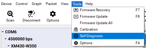
-
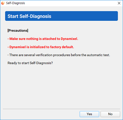
Self diagnosis will begin with a brief instruction.
WARNING : DYNAMIXEL will be factory reset during self diagnosis.
-
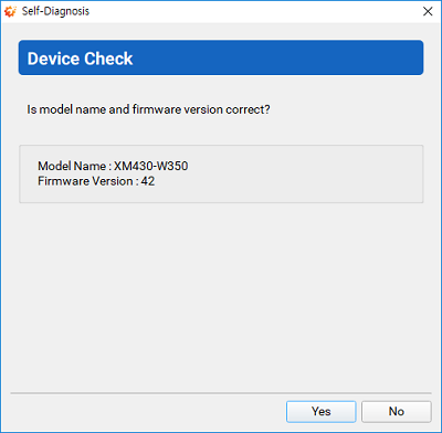
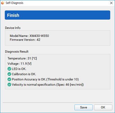
Confirm the model name and firmware version of DYNAMIXEL to perform diagnosis.
-
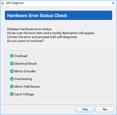
Check the hardware error status of DYNAMIXEL.
-
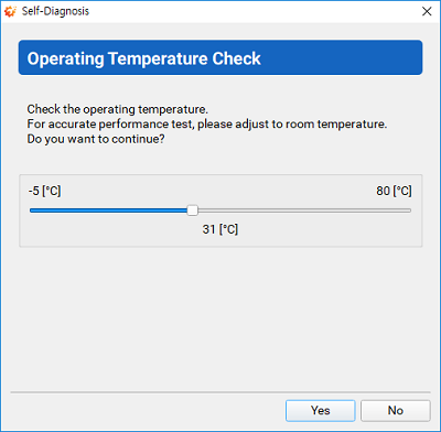
Check the operating temperature of DYNAMIXEL.
-
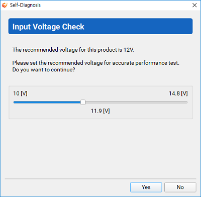
Check the input voltage of DYNAMIXEL.
-
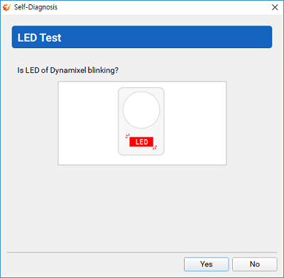
Check if the LED on DYNAMIXEL is blinking.
-
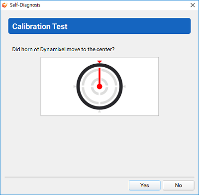
Check if DYNAMIXEL horn is at the center.
-
Proceed to performance test.
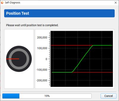
Position Test : Goal Position represents red line and Present Position represents green line.
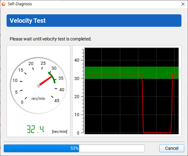
Velocity Test : Safe area represents a green zone.
-
Confirm the self diagnosis result.
Graph Optimization
In order to use the minimum communication interval(1 [ms]), please follow the instruction below.
USB Latency Setting
Windows
-
Open
Device Manager. Go toPortsitem and right click on the relative serial port to selectProperties.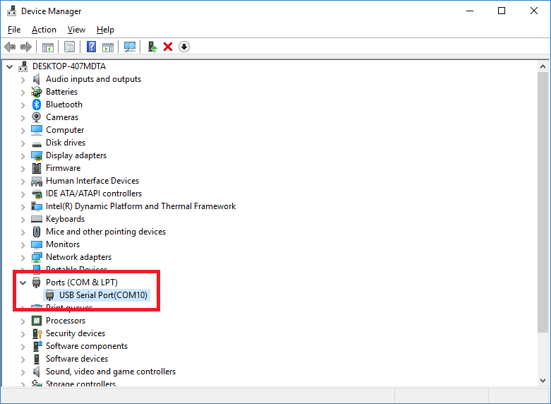
-
In the Properties window, go to
Port Settingstab and clickAdvancedbutton.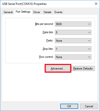
-
Set the
Latency Timer (msec)to1msand clickOKto confirm the change.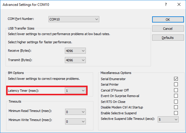
Linux
-
Execute below commands to configure the
latency_timerto1ms.# cat /sys/bus/usb-serial/devices/ttyUSB0/latency_timer 16 # echo 1 > /sys/bus/usb-serial/devices/ttyUSB0/latency_timer # cat /sys/bus/usb-serial/devices/ttyUSB0/latency_timer 1
DYNAMIXEL Setting
-
Open the graph options window to set
Intervalto1ms. Then, mark on theRead only selected item for Speedoption.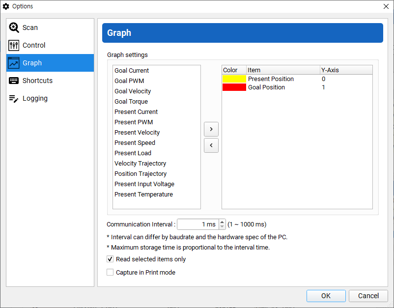
-
Set the baudrate of DYNAMIXEL to maximum and set
Return Delay Timeto0.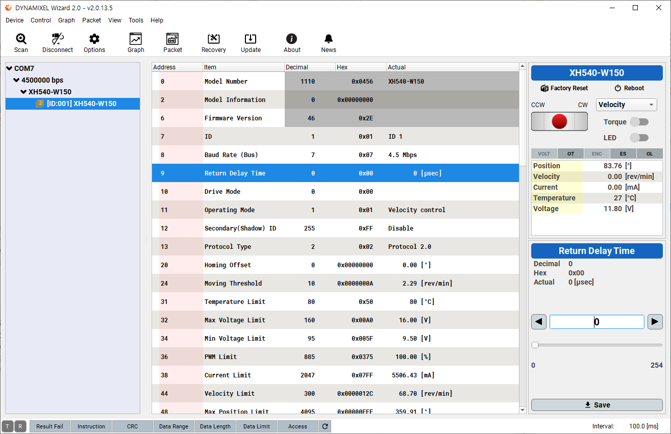
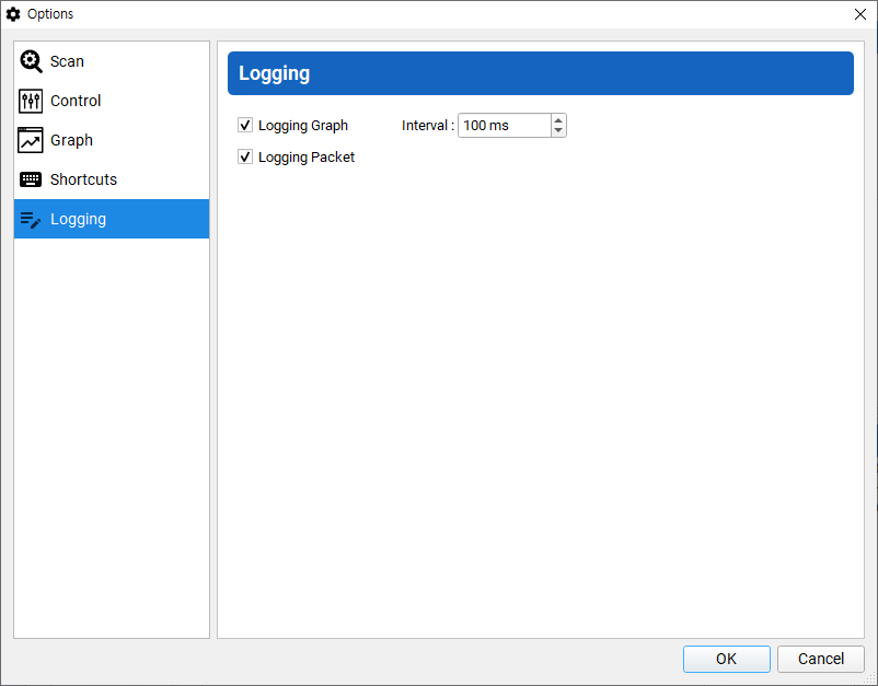
Logging
Save a log file of a packet information in DYNAMIXEL Wizard 2.0.
- In case of Graph, it saves the most nearest, the minimum, the maximum and the average value at your set interval.
-
In case of Packet, it saves every monitored packets.
Gragh Logging
Once starting the graph, the logging file is saved under Documents/DYNAMIXEL Wizard2/graph/
The whole path to save can be found at a title bar.
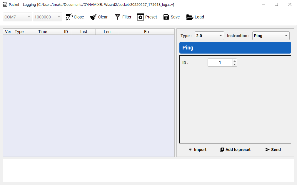
Packet Logging
Once opening the communication port, the logging file is saved under Documents/DYNAMIXEL Wizard2/packet/
The whole path to save can be found at a title bar.