Task Parameters
This section explains parameters used in R+ Task 3.0. It classifies the parameters that can be used by each device. Refer to the explanation and example codes of each item for details.
Controller Device
Accessory Device
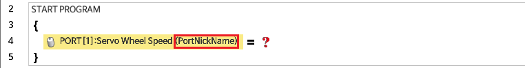
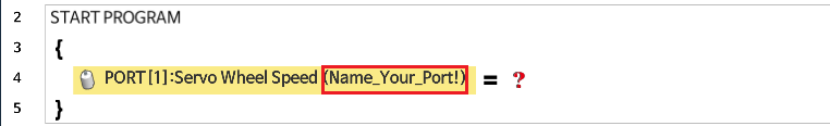
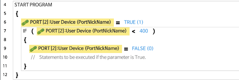
Port Nickname
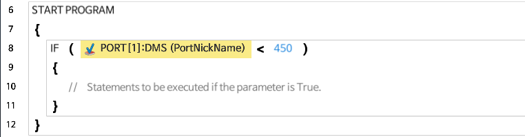
A nickname can be assigned to accessory devices that can be connected to the ROBOTIS 5-pin port.
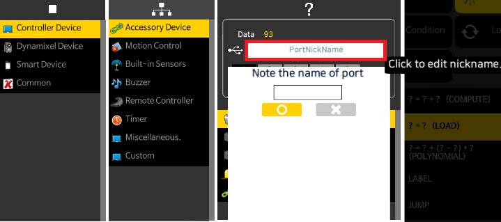
The following is an example of using the Port Nickname.
Geared Motor
- This is used to control the geared motor connected to the controller.
- Each Controller model has a different set of devices that can be connected to it. Please refer to the Controller Functionality Comparison for more detail. Controller Functionality Comparison
- Direction : CW (Clock Wise), CCW (Counter Clock Wise)
- Power : The value ranges from 0 to 1023, where 0 means stop and 1023 is 100% power capacity.
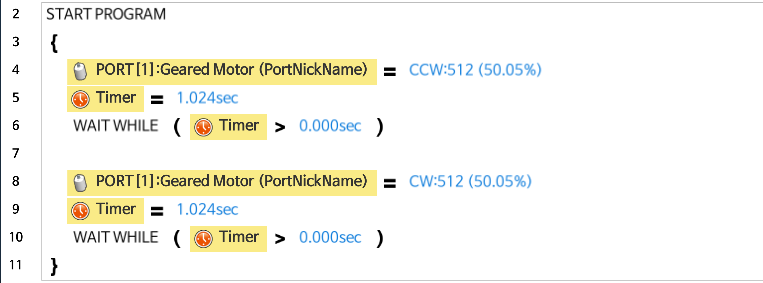
The following example is controlling the geared motor.
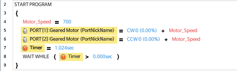
The following example is using the geared motor to move the robot forward.
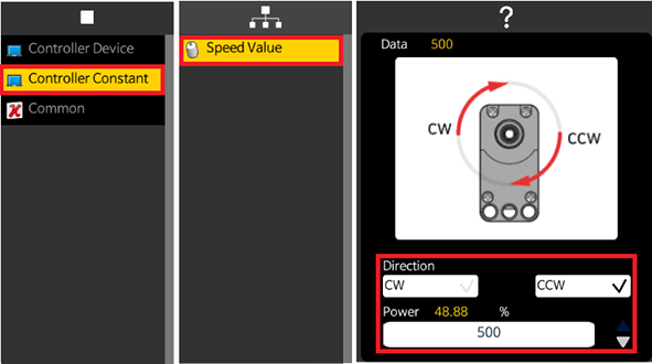
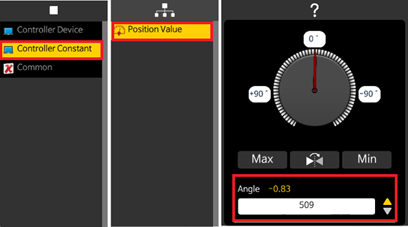
Servo Motor (Speed, Position)
- This is used to control the servo motor connected to the controller.
-
Each Controller model has a different set of devices that can be connected to it. Please refer to the Controller Compatibility for more detail.
-
Servo Mode : The Servo Motor can be set as Wheel or Joint mode.
-
Wheel Mode : Set the speed of the servo motor.
-
Joint Mode : Set the position of the servo motor.
-
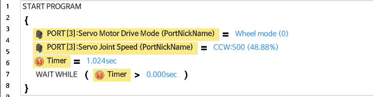
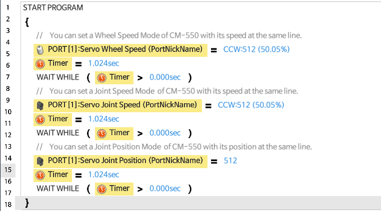
The following is an example of controlling the servo motor with Wheel Mode.
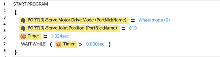
The following is an example of controlling the servo motor with Joint Mode.
CM-550 doesn’t require to set the Servo Mode as wheel control value or joint control value can be used in the option.
LED Module
- This is used to control the LED module connected to the controller.
- Each Controller model has a different set of devices that can be connected to it. Please refer to the Controller Compatibility for more detail. Controller Functionality Comparison
-
User can turn on/off the Right LED or Left LED.
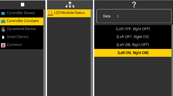
The following is an example of controlling the LED module.
Various Sensors
- This is used to control the various sensors connected to the controller.
- Each Controller model has a different set of sensors that can be connected to it. Please refer to the Controller Compatibility for more detail.
Touch Sensor
Detects whether there is contact with the touch sensor. (Returns True for contact, False for no contact)
- Touch Sensor Component Information
-
The following is an example of using the touch sensor.

Infrared Sensor
Measures the distance to the object (The value ranges from 0 to 1023, where the value increases from 0 as the object gets closer.)
- Infrared Sensor Component Information
-
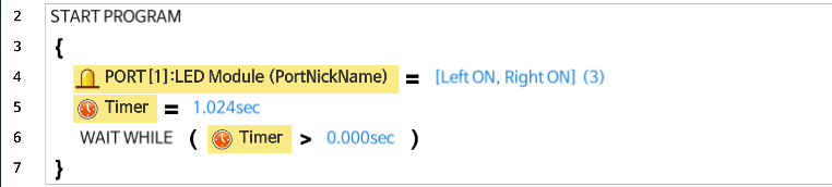
The following is an example of using the infrared sensor.
Distance Measurement Sensor
Measures the distance to the object (The value ranges from 0 to 1023, where the value increases from 0 as the object gets closer.)
- Distance Measurement Sensor Component Information
-
The following is an example of using the distance measurement sensor.
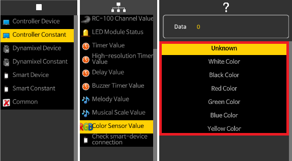
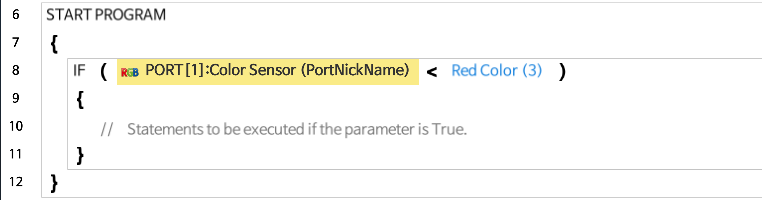
Color Sensor
Detects the color of an object.
-
The list of colors that the color sensor detects is as follows
- Color Sensor Component Information
-
The following is an example of using the color sensor.
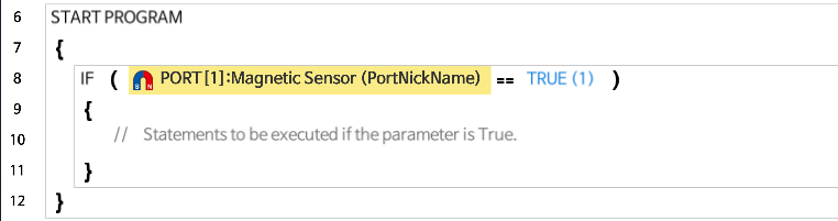
Magnetic Sensor
Detects magnetic materials near the sensor head (Returns True when magnetic property detected, False when not detected).
- Magnetic Sensor Component Information
-
The following is an example of using the magnetic sensor.
Temperature Sensor
Measures the temperature of an object (Temperature Range : -20 ~ 120 °C)
- Temperature Sensor Component Information
-
The following is an example of using the temperature sensor.
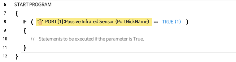
Motion Detection (Passive infrared) Sensor
Detects the motion of an object.
- Motion Detecting Sensor Component Information
-
The following is an example of using the motion detection sensor.
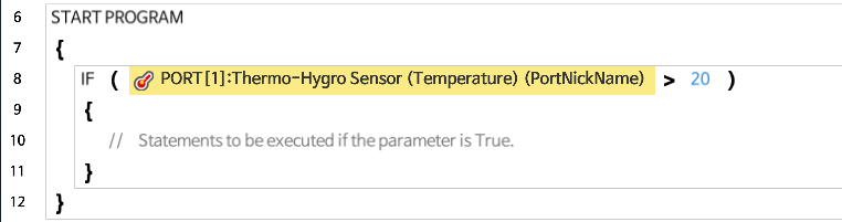
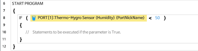
Temperature & Humidity (Thermo-hygro) Sensor
Measures the temperature and humidity of an object. (temperature range : -20 ~ 120 °C, humidity range : 0 ~ 100 %)
-
The following is an example of using the temperature and humidity sensor.
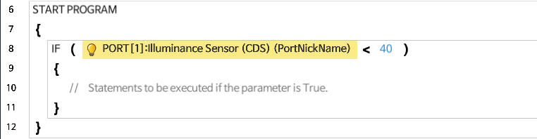
Illuminance Sensor (CDS)
Measures the brightness of the surroundings (The value ranges from 0 to 1023, where the value increases from 0 as the surroundings gets brighter).
-
The following is an example of using the illuminance sensor.
User Device
Reads the output value of the user-created sensor.
- Building a User Device
-
The following is an example of using the user device.
Motion Control
- This section describes specific parameters for executing motions downloaded on controller via R+ Motion.
- Only specific controllers support motion control. (Supported controllers : CM-200, CM-5, CM-510, CM-530, CM-550, CM-700, OpenCM 9.04)
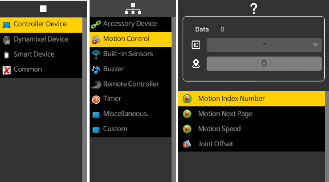
Motion Index Number
Executes a motion by calling the corresponding Motion Index Number. If the Motion is being executed, you can read the current Motion Index Number.
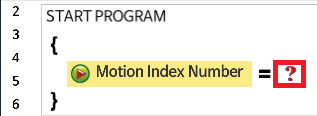
The following is an example of using the Motion Index Number.
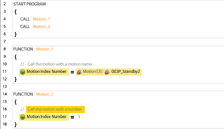
- Motion Index Number number 0 : Motion stop using an Exit Motion unit.
- Motion Index Number number -1 : Motion stop at the current unit.
- Motion Index Number number -2 : Motion stop at the current Key Frame (Only CM-550).
- Motion Index Number number -3: Immediate Motion stop (Only CM-550).
The more information on Key-Frame, Motion Unit and Motion is avilable at Motion Programming
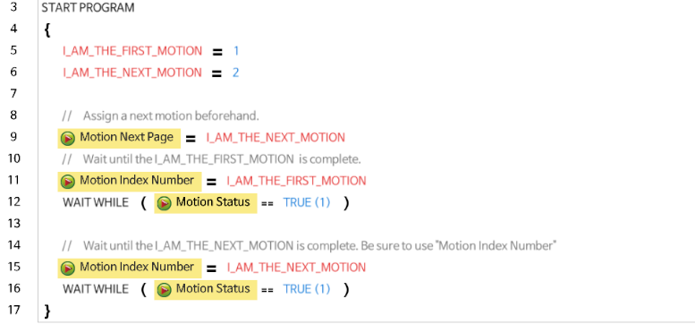
Motion Next Page
Assin a next motion unit to the current running motion unit. The Motion Next Page can be used to link two motions for seamless motion flow.
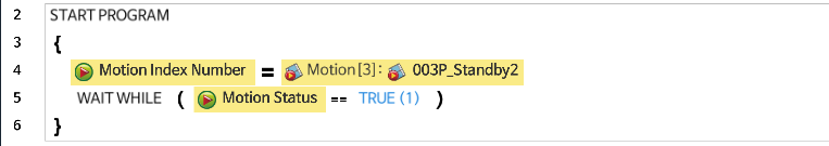
Motion Status
Returns True if motion is being executed, returns False if motion is not being executed.
The following is an example of using the Motion status to wait until the motion finishes.
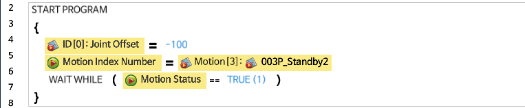
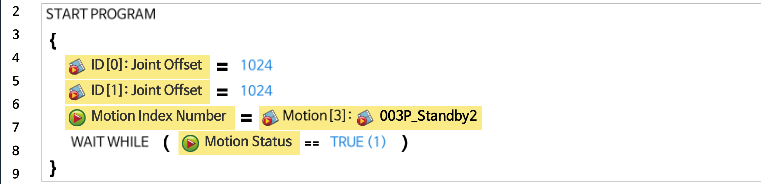
Joint Offset
When a motion is executed, it adds a value between -255~255 to every joint. For instance, if the joint offset is -50 and the location values for the motion data have been set to 300 -> 400 -> 500, the location values will be changed to 250 -> 350 -> 450 and then executed.
The following is an example of applying an offset values to a specific joint.
The following is an example of configuring a specific joint to not be affected by the Motion data values.
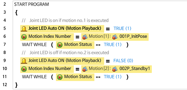
Joint LED Auto ON
Turns on/off DYNAMIXEL LED while a Motion is being executed. This feature is only supported in OpenCM 9.04
The following is an example of using the “turn on joint LED automatically” function when executing a Motion.
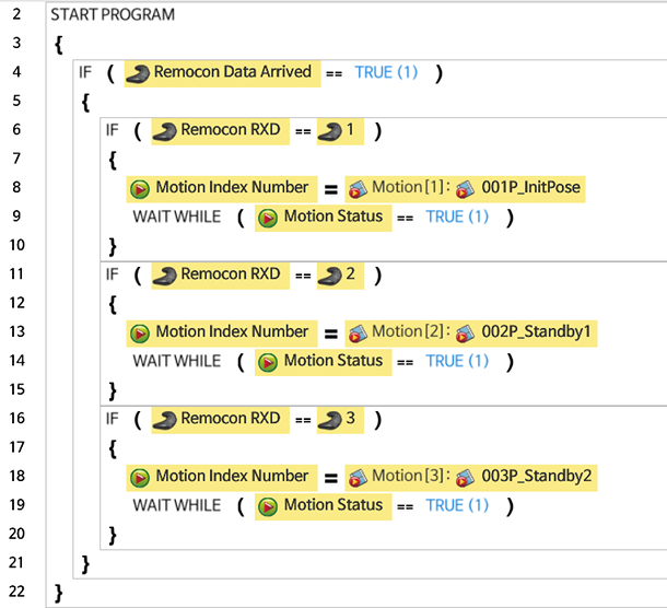
Pressing different buttons on the Remote Controller will execute their corresponding Motions.
Built-in Sensor
This option allows to access various sensors and features built in the controller.
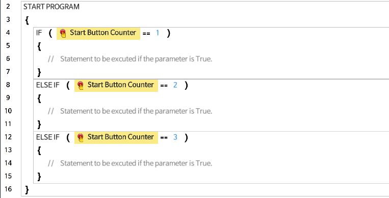
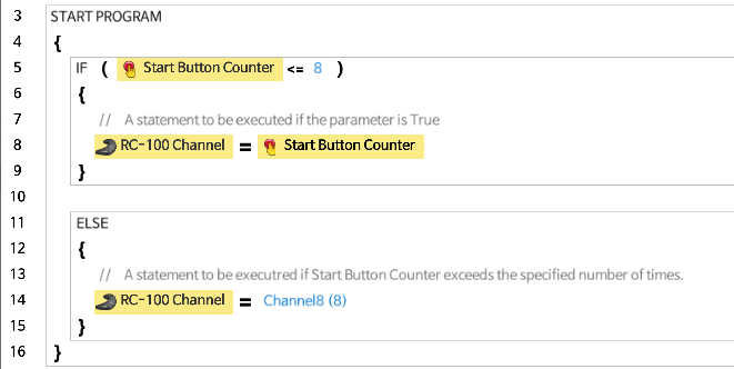
Start Button Counter
Reads the number of START button click while the Controller is turning on. The value of the Start Button Counter ranges from 0 to 255.
Supported Controllers : CM-5, CM-50, CM-100A, CM-150, CM-200, CM-510, CM-530, CM-700, OpenCM 7.0, OpenCM 9.04
The following is an example of using the Start button counter.
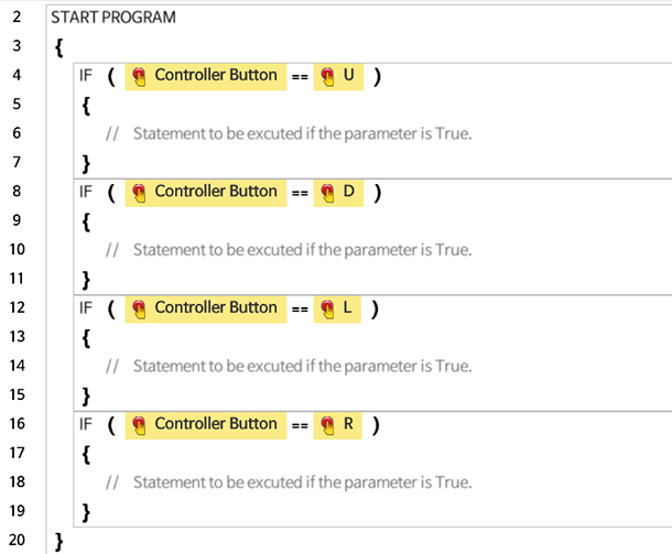
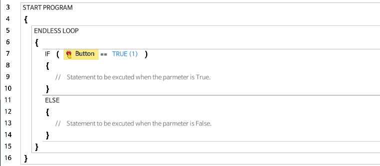
Controller Button / Button
Reads the status of the Controller’s buttons. Each Controller may have different buttons that can be used.
Supported Controllers : CM-5, CM-50, CM-100A, CM-150, CM-200, CM-510, CM-530, CM-550, CM-700, OpenCM 7.0, OpenCM 9.04
The following is an example of using buttons for CM-5, CM-510, CM-530.
The following is an example of using buttons for OpenCM9.04.
Button Released Event
When the START button of CM-550 is released, this value is updated to 1(True), and the value will be reset to 0(False) after the data is read.
Button Pressed Timer(ms)
Button Pressed Timer counts up in millisecond while pressing the button of CM-550.
Button Pressed Timer(s)
Button Pressed Timer counts up in second while pressing the button of CM-550.
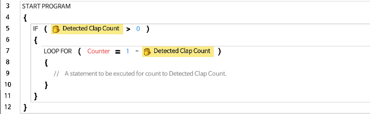
Detected Clap Count
This function uses the Controller’s embedded mic to save the detected clap count. If you want to reset the counter, write 0 to the address.
Supported Controllers : CM-5, CM-50, CM-100A, CM-150, CM-200, CM-510, CM-530, CM-550, CM-700, OpenCM 7.0, OpenCM 9.04
The following is an example of using the Detected Clap Count.
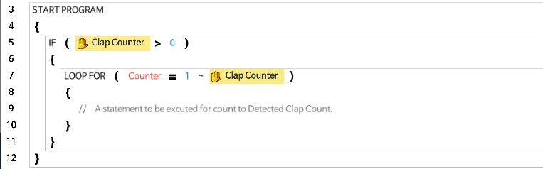
Clap Counter
This function counts the number of claps. If next clap is not detected within 0.8 seconds, the counter will be reset to 0.
The following is an example of using the Clap Counter.
Infrared Sensors
- This function is used to read the value of the infrared sensor embedded in the Controller.
- The value of the infrared sensor ranges from 0 to 1023, where the value increases from 0 as the object gets closer.
- Each Controller model supports different types of sensors. Please refer to each Controller’s manual for more detail. (Supported Controllers : CM-5, CM-50, CM-100A, CM-150, CM-200)
The following is an example of using the values of the infrared sensors of the Controller.
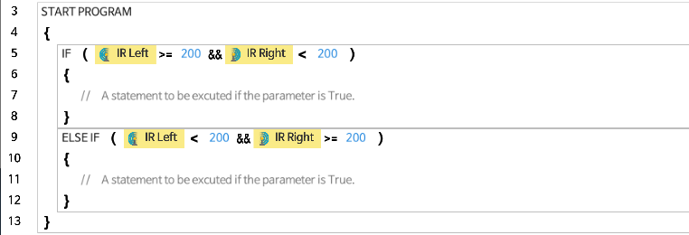
Left Infrared Sensor
Reads the value of the infrared sensor located at the bottom left side of the Controller.
Center Infrared Sensor
Reads the value of the infrared sensor located at the front and center of the Controller.
Right Infrared Sensor
Reads the value of the infrared sensor located at the bottom right side of the Controller.
Present Input Voltage
Reads the supplied voltage of the controller.
Controller Temperature
Reads present temperature of the CM-550.
IMU Orientation
Based on the assembly of CM-550, configure the orientation of CM-550 controller. Vertical and horizontal orientations can be defined as below.
| Controller Orientation | Value |
|---|---|
| Vertical | 0 |
| Horizontal | 1 |
Roll X / Pitch Y / Yaw Z
Read Roll / Pitch / Yaw data from the IMU in CM-550 controller. (Unit : 0.01 °)
Gyro X / Y / Z
Read Gyro X / Y / Z data from the IMU in CM-550 controller. (Unit : 0.01 °/s)
Accel X / Y / Z
Read Accelerometer X / Y / Z data from the IMU in CM-550 controller. (Unit : 0.001 G)
Buzzer
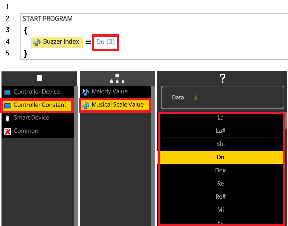
Buzzer Index / Buzzer Timer
- This is used to play a musical scale or a melody using the Buzzer embedded in the Controller.
- The Buzzer Timer should be configured first before selecting the Buzzer Index in order for the Buzzer to sound properly.
The following figure shows the screens to select the type of buzzer.
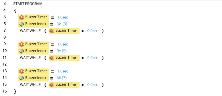
The following is an example of playing a musical scale from the Controller. When playing a musical scale, the Buzzer Timer can be set between 0 ~ 5 seconds.
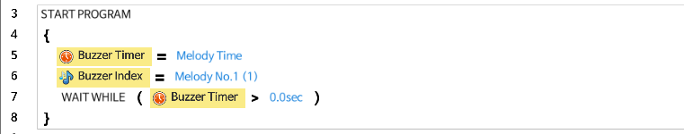
The following is an example of playing a melody from the Controller. When playing a melody, the Buzzer Timer should be set with Play special melody option.
Remote Controller
- These are the parameters that send and receive data with external devices using the wireless communication module (Bluetooth, IR, ZIGBee) connected to the Controller.
- It is generally used when controlling a robot with the RC-100 or smartphone virtual remote controller, but it can also be used to communicate with a user developed software.
- The data is restricted to 2 Byte value (0 ~ 65,535 or 0x0000 ~ 0xFFFF).
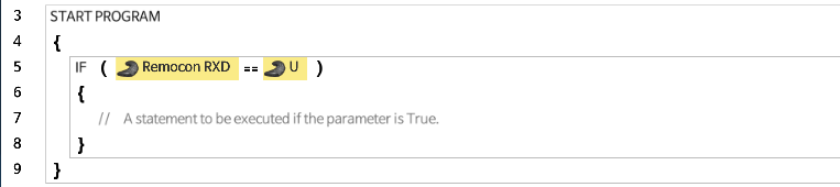
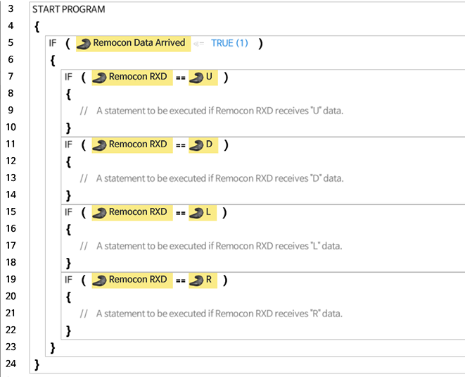
Remocon RXD
This function is used to read the received value of the Controller.
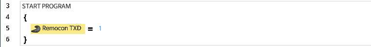
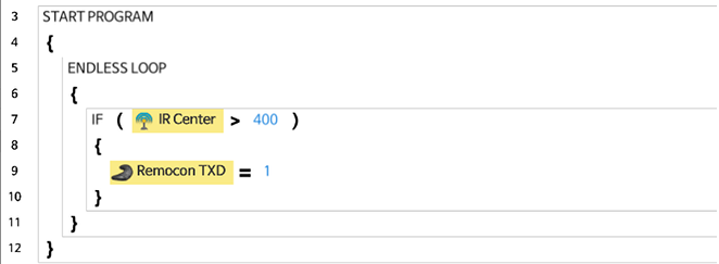
Remocon TXD
This function is used when the Controller transmits data to other devices.
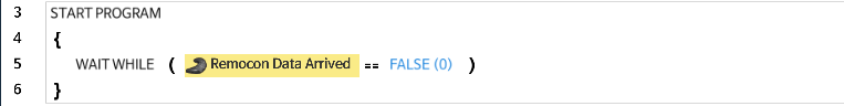
Remocon Data Arrived
If the Controller receives data, this address is updated to True.
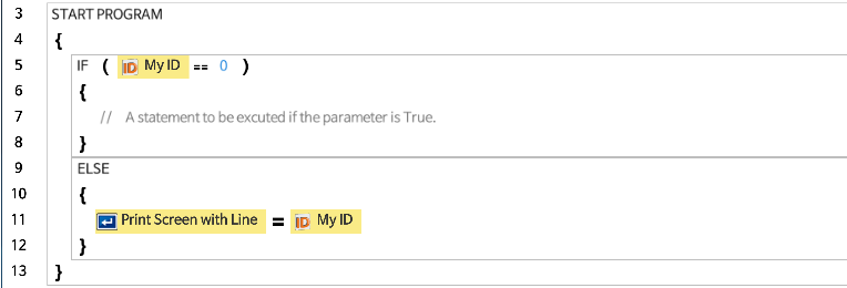
My ID
This address configures the ZIGBee ID of the controller.
Remocon ID
This address configures the ZIGBee ID of the remote controller.

RC-100 Channel
Configures the IR receiver channel when using an infrared receiver (If this address is set to 255, RC-100 will operate as Bluetooth or ZIGBee).
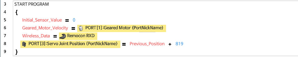
The following is an example of processing a wireless data received from the Controller.
The following is an example of the Controller sending data to the outside.
Timer
Timer and High-resolution Timer are used to set the time to count-down.
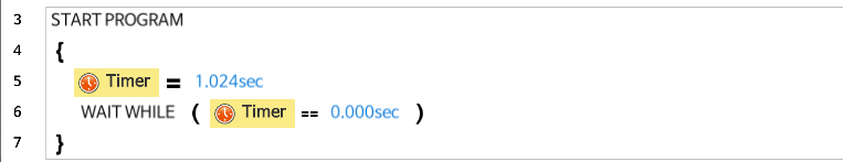
Timer
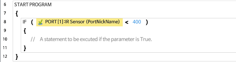
This is used to set the time of the Controller to count-down. The value of the Timer ranges from 0 to 255, and the unit is 0.128 second.
The following is an example of using Timer to wait approximately 1 second (1.024 seconds).
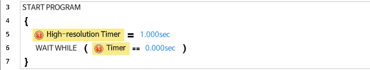
High-resolution Timer
This has the same function as Timer but counts the time more precisely. The value of the Timer ranges from 0 to 65,535, and the unit is 0.001 second.
The following is an example of using Precision Timer to wait exactly 1 second (1.000 second).
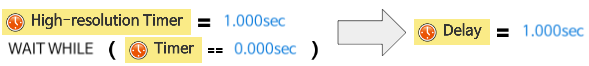
Delay
CM-550 supports Delay function that can simplifies the combined usage of Timer and WAIT WHILE.
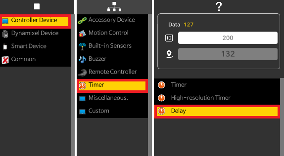
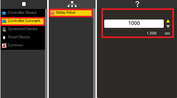
The following is an example of replacing Timer and WAIT WHILE with Delay function with CM-550.
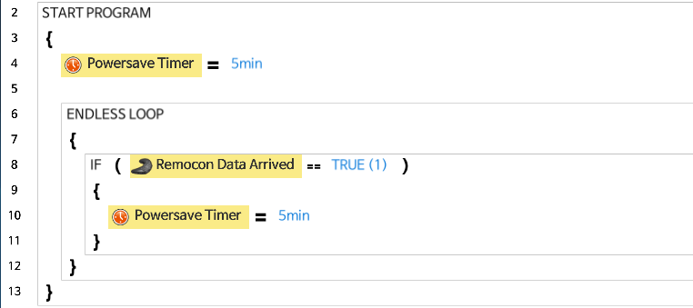
Powersave Timer
This is used to control the power saving mode of controllers.
- The value of the Powersave Timer ranges from 0 to 255 (Unit : minute).
- The default value of the Powersave Timer is
5. - Setting this value to
0will deactivate power saving mode except OpenCM7.0. - It is recommended to use Powersave Timer to prevent battery over discharge.
| Value | OpenCM7.0 Timer | Other Controller Timer |
|---|---|---|
| 0 | 60 minutes | * Timer not used |
| 1 ∼ 60 | 1 ∼ 60 minutes | 1 ∼ 60 minutes |
| 61 ∼ 254 | 60 minutes | 61 ∼254 minutes |
| 255 | * Timer not used | 255 minutes |
* Battery can be over discharged when power saving is deactivated.
CAUTION: Be aware that OpenCM7.0 has different configuration compare to other controllers.
The following is an example of using Powersave Timer to configure sleep mode for the Controller. If a new wireless data arrives within 5 minutes, it resets the Powersave Timer value.
Controller: Miscellaneous
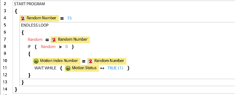
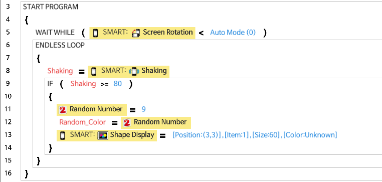
Random Number
Generate a random number between 0 and a maximum value. You can set a number as the maximum value. The valid value is from 0 to 255
The following is an example of using Random Number to execute a random motion. This is done by generating a random number between 0 and 15 to execute a corresponding motion.
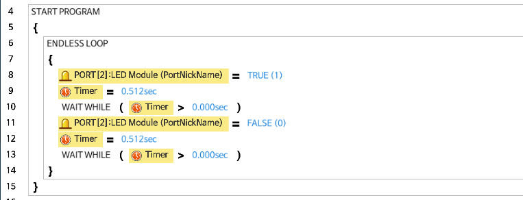
Built-in LED
Control the build-in LED (Aux LED)
The following is an example of using a built-in LED. It is turning the built-in LED on and off every 0.512 second interval.
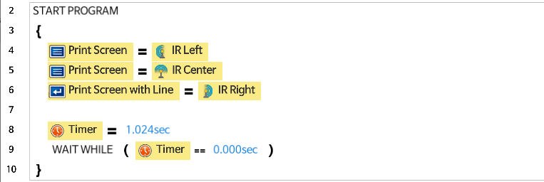
Print Screen
Print a specific value from the task code on the screen
Print Screen with line
Print a specific value from the task code on the screen, and print the new line.
The following is an example of using Print Screen and Print Screen with Line to print the sensor value.
Controller: Custom
- Directly read from or write to the address of an external device such as DYNAMIXEL.
- User can read/write by selecting the specified address in units of Byte, Word, or DWord. Write or read in Byte or DWORD variable to write/read on user accessed address
- Please refer to DYNAMIXEL Control Table for more detail.
DYNAMIXEL Device
These are the parameters for reading or writing values in DYNAMIXEL Control Table. Please refer to DYNAMIXEL Control Table for more details.
DYNAMIXEL
- DX / RX / AX supported parameters :
Torque On/Off, LED, CW margin / CCW margin, CW slope / CCW slope, Goal Position, Goal Velocity, Goal Torque, Present Position, Present Velocity, Present Load, Present Input Voltage, Present Temperature, Is Moving - MX supported parameters :
Torque On/Off, LED, PID Gains, Goal Position, Goal Velocity, Goal Torque, Present Position, Present Velocity, Present Load, Present Input Voltage, Present Temperature, Is Moving, Sensed Current, Torque Control Mode, Goal Acceleration - X supported parameters :
Operating Mode, Torque On/Off, LED, Velocity PI gain, Position PID Gains, Goal PWM, Goal Current, Goal Velocity, Profile Acceleration, Profile Velocity, Goal Position, Is Moving, Present PWM, Present Current, Present Position, Present Velocity, Present Input Voltage, Present Temperature
Operating Mode
Configure the Operating Mode of DYNAMIXEL. Please refer to Operating Mode of each DYNAMIXEL.
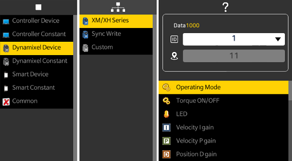
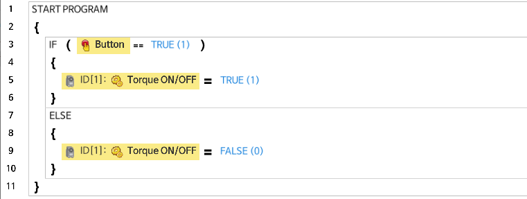
Torque On/Off
Turn DYNAMIXEL Torque on/off. Torque is turned on when True, Torque is turned off when False.
The following is an example of turning on the Torque of DYNAMIXEL with ID number 1 when the Controller’s button is pressed.
LED
Turn DYNAMIXEL LED on/off. LED is turned on when True, LED is turned off when False.
CW margin / CCW margin
Read or write DYNAMIXEL Margin value. The range of the value is from 0 to 255, but it is recommended not to change the default value (1).
Please refer to DYNAMIXEL Control Table for more detail.
CW slope / CCW slope
Read or write DYNAMIXEL Slope value. There are a total of seven phases which the value can be set to, and the representative values of each phase are set as in the table below.
Please refer to DYNAMIXEL Control Table for more detail.
| Level | Real Data Value | Representative Data Value |
|---|---|---|
| 1 | 0 (0x00) ~ 3(0x03) | 2 (0x02) |
| 2 | 4(0x04) ~ 7(0x07) | 4 (0x04) |
| 3 | 8(0x08) ~ 15(0x0F) | 8 (0x08) |
| 4 | 16(0x10) ~ 31(0x1F) | 16 (0x10) |
| 5 | 32(0x20) ~ 63(0x3F) | 32 (0x20) |
| 6 | 64(0x40) ~ 127(0x7F) | 64 (0x40) |
| 7 | 128(0x80) ~ 254(0xFE) | 128 (0x80) |
PID Gains
Read or write DYNAMIXEL PID values.
P gain refers to Proportional Gain, for which the smaller the value is the larger the clearance gets, and the power level decreases near the target location.
I gain refers to Integral Gain, and D gain refers to Derivative Gain.
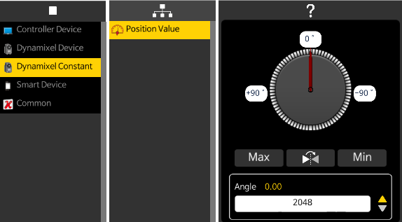
Goal Position
Read or write DYNAMIXEL Goal Position.
The Position Value control can be used to designate the angle position as shown below.
Goal Velocity
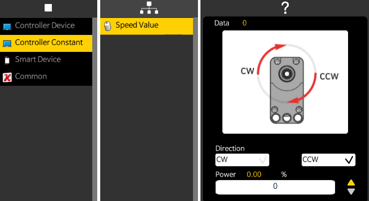
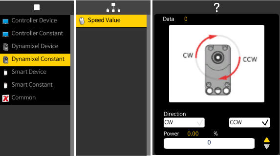
Read or write DYNAMIXEL Goal Velocity.
The Speed Value control can be used to designate the rotation direction and power value as shown below.
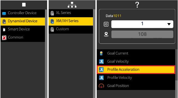
Profile Acceleration
Read or write the Profile Acceleration of DYNAMIXEL-X series.
Please refer to Profile Acceleration(108).
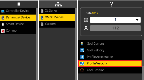
Profile Velocity
Configure the maximum velocity of the profile when DYNAMIXEL-X series is running under Position Control mode or Extended Position Control mode.
Please refer to Profile Velocity(112).
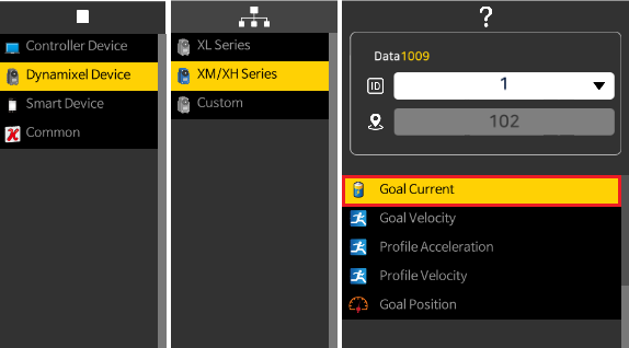
Goal Current / Goal Torque
Configure the current or torque limit of DYNAMIXEL.
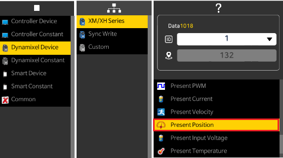
Present Position
Read the Present Position of DYNAMIXEL.
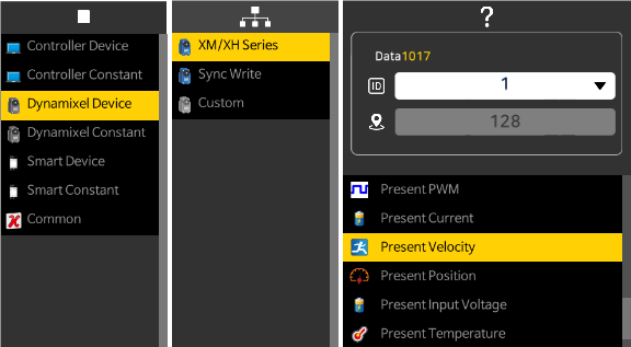
Present Velocity
Read the Present Velocity of DYNAMIXEL.
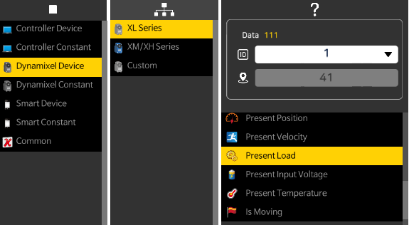
Present Load
Read the direction and amount of load currently applied to DYNAMIXEL.
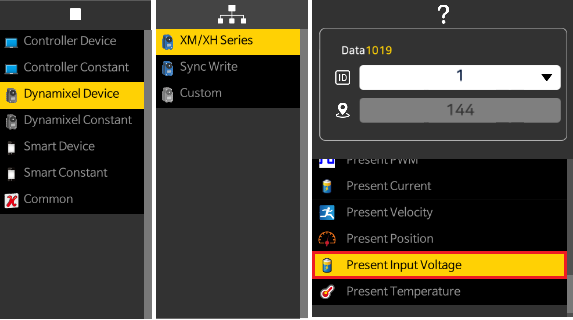
Present Input Voltage
Read the present voltage supplied to DYNAMIXEL.
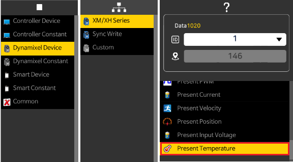
Present Temperature
Read the present temperature of DYNAMIXEL.
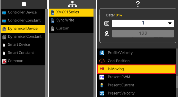
Is Moving
Identify if DYNAMIXEL is in motion. Returns True while in motion.
SyncWrite
CM-550 supports Protocol 2.0 - SyncWrite.
SyncWrite Command
Use SyncWrite Command to build and transmit the packet. Please refer below table for details.
| Parameter | Command | Example |
|---|---|---|
| 0 | Start SyncWrite Packet |  |
| 1 | Build SyncWrite Packet |  |
| 2 | Transmit SyncWrite Packet |  |
SyncWrite Address
Specify DYNAMIXEL address to write the data.

Define the starting address to 116.
SyncWrite Length
Specify the length of data.

Use 4 byte data.
SyncWrite ID
Specify DYNAMIXEL ID to write.

ID 2 DYNAMIXEL will receive the data.
SyncWrite Data
Specify the data value to transmit.

Use 2048 as the data value.
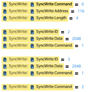
SyncWrite Example
The following is an example of SyncWrite instruction to transmit the value 2048 to the target address 116(Goal Position) of DYNAMIXEL ID 2 and 3.
IR Array Sensor
- Infrared sensor value (numbers 1~7) : Read the infrared sensor value from the infrared sensor array.
The measured value can vary depending on the color or texture of the wall or object, and the sensor is optimized for use within 0 to 5 cm. - Infrared detection standard value (numbers 1~7) : These values are used as reference values for the infrared sensor array to determine whether the color is black or white.
| Black detection | LED | |
|---|---|---|
| Sensor value <= set value | BIT 1 | ON |
| Sensor value > set value | BIT 0 | OFF |
- Buzzer index : Configure the type of Buzzer for the infrared sensor array
- Buzzer timer : Configure the duration of the Buzzer sound in the case that the infrared sensor array’s Buzzer is used.
The Buzzer timer should be configured first and then the type of Buzzer (or Buzzer index) configured afterwards for the Buzzer to work properly. - Auto configuration of detection standard value : Define the beginning and end of auto-searching the detection standard values of the color black Refer to the example below for more detail.
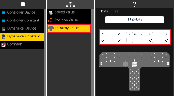
- Infrared object detection result : Read whether an object has been detection in the infrared sensor array
| Binary value | Decimal value | Black detection |
|---|---|---|
| 0000001 | 1 | Black detection for IR sensor #1 |
| 0000010 | 2 | Black detection for IR sensor #2 |
| 0000100 | 4 | Black detection for IR sensor #3 |
| 0001000 | 8 | Black detection for IR sensor #4 |
| 0010000 | 16 | Black detection for IR sensor #5 |
| 0100000 | 32 | Black detection for IR sensor #6 |
| 1000000 | 64 | Black detection for IR sensor #7 |
Use can check the value while looking at the screen as shown below.
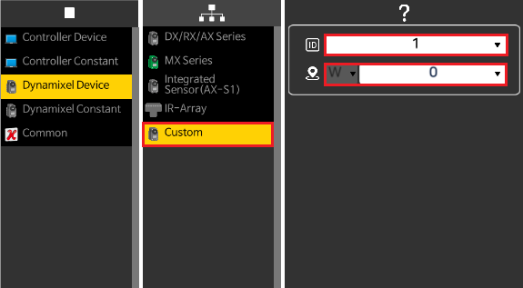
DYNAMIXEL: Custom
- User can access the address of an external device such as DYNAMIXEL directly to perform read/write tasks.
- User can read/write by selecting the specified address in units of Byte, Word, or DWord.Write or read in Byte or DWORD variable to write/read on user accessed address
- Please refer to DYNAMIXEL Control Table for more detail.
Smart Device
This parameter grants access to the control table of the Apps(R+ Smart, R+ IoT, R+ ENGINEER) connected to controllers.
Camera
This parameter can access the camera of smart device.
Camera Selection
Select which camera to use in the smart device. The following example shows switching between front and rear camera.
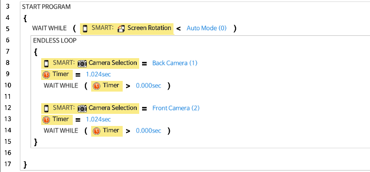
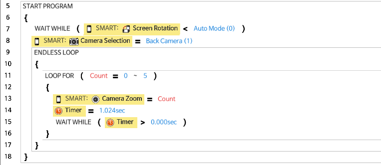
Camera Zoom
Select zoom level of the camera (Value range : 0 ~ 255).
The following example increases zoom level every 1.024 second.
Camera Sensor
Use the smart device camera as a sensor.
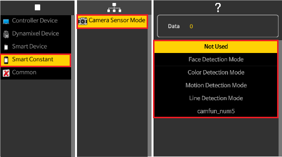
NOTE: Please refer to Vision for more details.
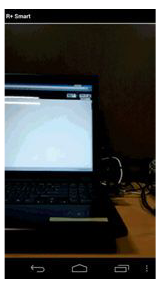
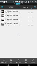
Take Picture
Take a picture with the camera of smart device. (Take pictures when True, stop when False)
The following is an example of taking pictures with rear camera.

Vision
This parameter use the camera of smart device as various vision sensors.
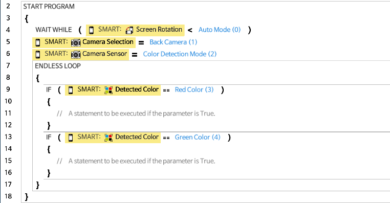
Detected Color
Identify the color from the center of screen. The following is an example of detecting the color.
Tracking Color(Line-Tracer)
Select the color from the screen to detect.
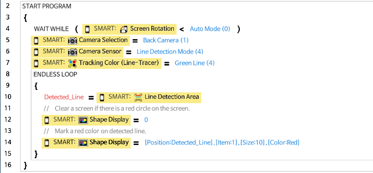
Line Detection Area
Identify the location of detected line. The following is an example of displaying a red circle over the detected green line.

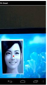
Face Detection Area
When the face is detected from the camera screen, the detected area is marked. The red dot is marked on the detected face in the following example.

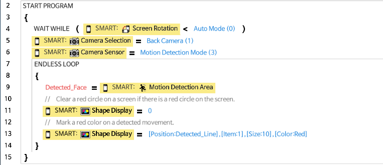
Motion Detection Area
When a motion is detected from the camera screen, the detected area is marked. The red dot is marked on the motion detected area in the following example.
Display
This parameter is used to display images, shapes, characters, and numbers on the screen of the smart device.
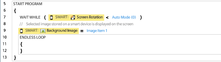
Screen Rotation
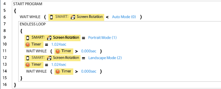
This parameter sets the orientation of the smart device.
The following example changes the orientation of the screen every 1.024 second.
Background Image
This parameter sets the image on the background of the screen. (Registered images in the app can be used).
The following is an example of setting Image Item 1 to background image.
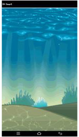
Foreground Image
This parameter sets the image on the screen. (Registered images in the app can be used).
The following is an example of displaying Image Item 1 and Image Item 2 at location (2, 3) and (4, 3).
Mask Image (Face Detection)
When using Face Detection mode, a masking image can be overlayed on the detected face. (Registered images in the app can be used).
The following is an example of overlaying Image Item 2 on the detected face.


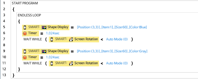
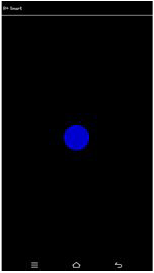
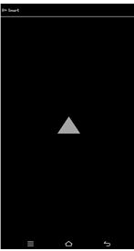
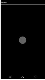
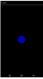
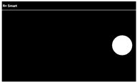
Shape Display
Insert shapes on the screen (1: Circle, 2: Rectangle, 3: Triangle)
The following is an example of displaying blue circle and gray triangle sequentially.
Text Display
Insert text or character on the screen (Registered text in the app can be used).
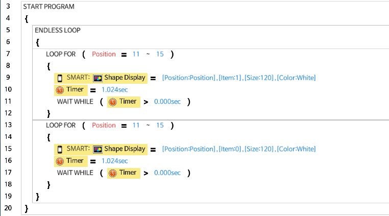
The following is an example of displaying and erasing a character through location (1, 3) and (5, 3).
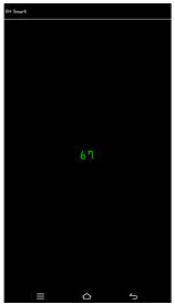
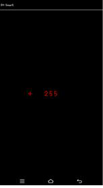
Number Display
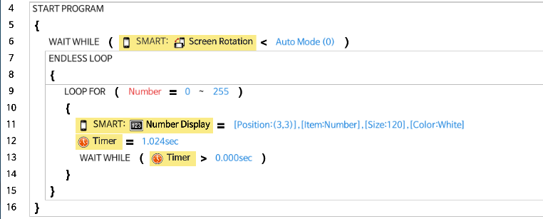
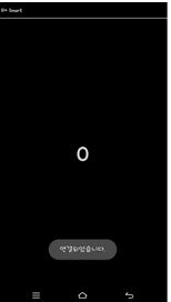
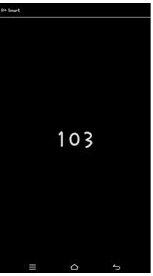
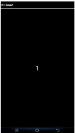
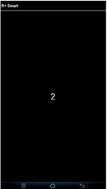
Insert a number on the screen (Numbers between 0 ~ 255 can be used).
The following is an example of displaying a number that increases every 1.024 second at location (3, 3).
Multimedia
Play video and sound from the smart device.
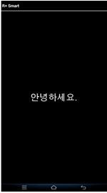
Text to Speech (TTS)
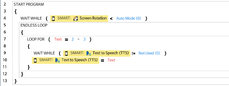
Use TTS feature of the smart device (Registered sentences can be used).
The following is an example of using TTS for Text Item 1 and Item 2.
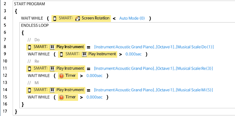
Play Instruments
Use smart device to play various instruments.
The following is an example of playing Do, Re, Mi with Acoustic Grand Piano.
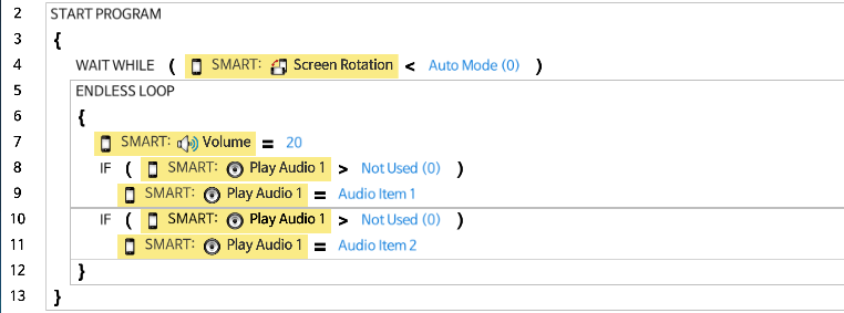
Play Audio
Play audio files in the smart device. The Audio 1 and Audio 2 are independent to each other (Registered audio files in the app can be played).
Volume
Configures the sound volume of the smart device.
The value range is 0 ~ 255, and larger number will increase the volume. The effective value range may differ by devices.
The following is an example of playing an Audio Item 1 and Audio Item 2.
Play Video
Play video files in the smart device. (Registered video files in the app can be played).
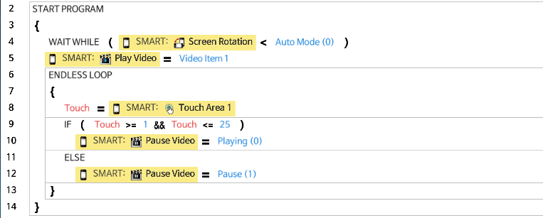
Pause Video
Stop playing the video file for a moment.
The following is an example of pausig the Video Item 1 while touching the screen.
Sensors
This parameter grants access to various sensors in the smart device.
Impact
Read the impact of smart device. Depending on the extent of impact, the value between 0 and 255 is displayed.
The following is an example of reading impact and changing the color of the shape.
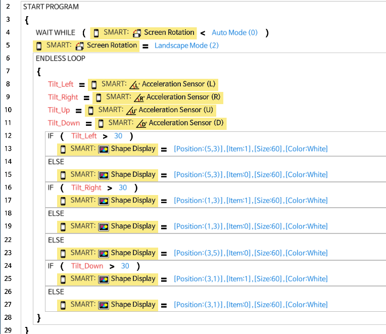
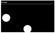
Gyro Sensor
Read the Gyro sensor of smart device. Degree of rotation for (Left), (Right), (Up), (Down) directions are displayed between 0 ~ 90°.
The following is an example of displaying a circle based on the Gyro values.

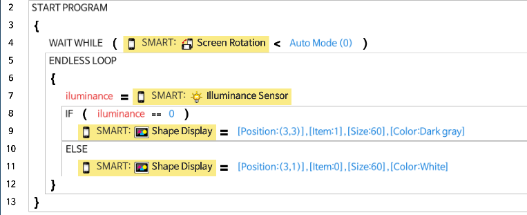
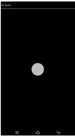
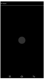
Illuminance Sensor
Read the environment brightness of smart device. Depending on the brightness, the value between 0 and 65,535 is displayed. The effective value range may differ by devices.
The following is an example of using the Illuminance sensor to change the color of the shape.
Magnetic Field Sensor
Read the magnetic field near the smart device. The value between 0 and 65,535 is displayed.
The following is an example of using the Magnetic Field Sensor.

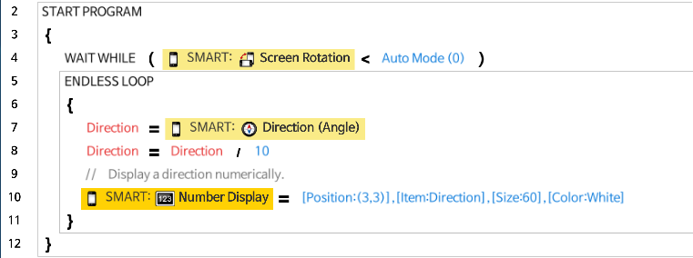
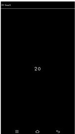
Direction (Angle)
Read the orientation of smart device. The value betwee 0 and 359 is diplayed based on the heading of smart device (0: North, 90: East, 180: South, 270: West).
The following is an example of reading Direction.
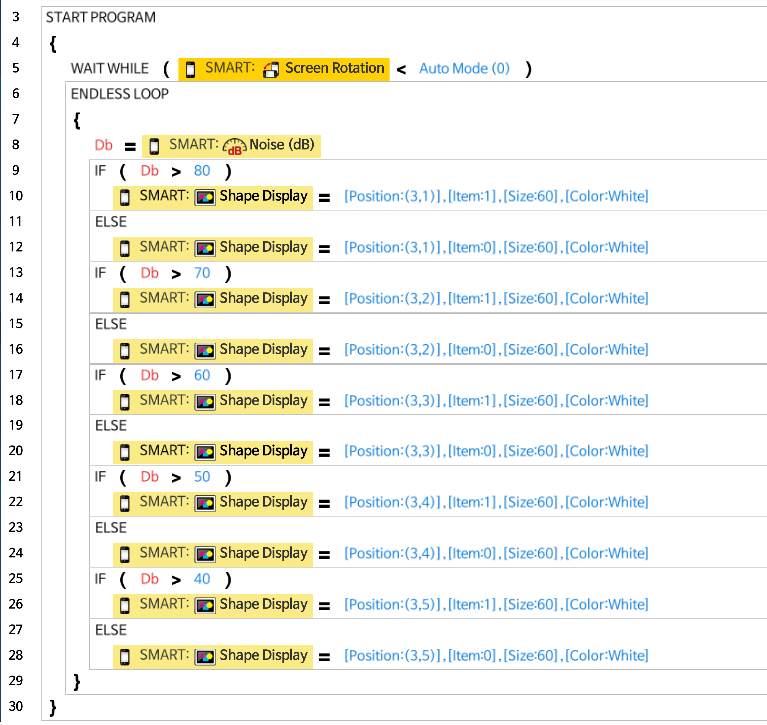
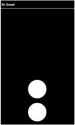
Noise (dB)
Read the noise level near the smart device. The value between 0 ~ 255 is displayed.
The following is an example of reading noise level.
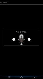
Speech Recognition
Switch the speech recognition of smart device. If set to Ture, speech recognition will be enabled.
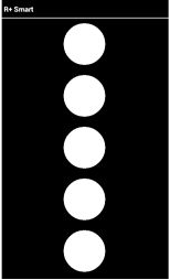
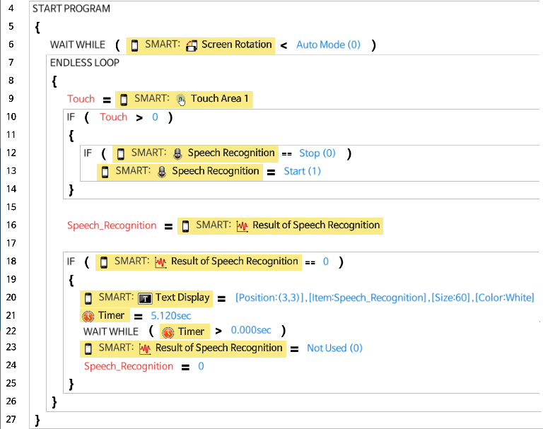
Result of Speech Recognition
When Speech Recognition is enabled, this parameter will return the result of recognition.
If the speech is properly recognized, the result will return a value of matching sentence number between 1 and 199. If the speech is not matching any of the sentences, it will return 0.
The following is an example of speech recognition.
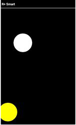
Touch Area
Read the location of touched coordinate of smart device. Touch Area 2 can used when more than one touch inputs are required.
The following is an example of reading Touch Area 1 and Touch Area 2 to display circles at touched coordinates.


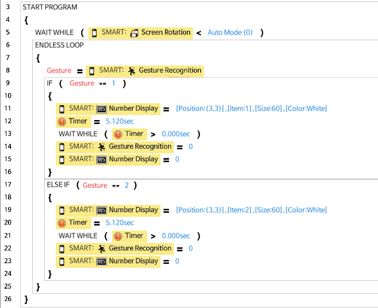
Gesture Recognition
Use the gesture recognition of smart device.
The following is an example of recognizing gestures.
Smart Device: Miscellaneous
Use additional features of smart device.
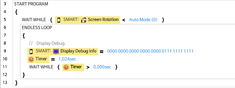
Display Debug Info
Display information regarding specific feature of smart device.
Setting each bit to 1 will display below information on the screen.
| Bit | Equivalent Decimal Value | Information |
|---|---|---|
| 1st Bit | 1 | Debug coordinate and color related to Vision |
| 2nd Bit | 2 | Debug Impact value |
| 3rd Bit | 4 | Debug Gyro values |
| 4th Bit | 8 | Debug Illuminance value |
| 5th Bit | 16 | Debug Magnetic Field value |
| 6th Bit | 32 | Debug Direction value |
| 7th Bit | 64 | Debug Noise value |
| 8th Bit | 128 | Debug Touch Area 1 and 2 values |
| 9th Bit | 256 | Debug Speech Recognition result value |
| 10th Bit | 512 | Debug SMS number and message |
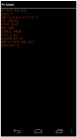
The following is an example of debugging information.
Print Screen
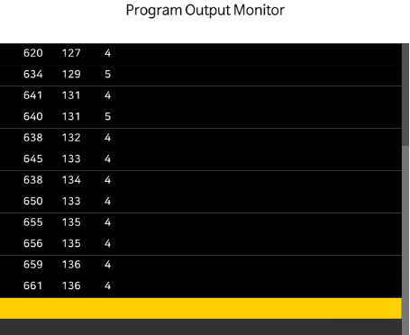
Print the specific value on terminal window or output monitor.
Print Screen with Line
Print the specific value on terminal window or output monitor. New line will be inserted after printing values.
The following is an example of using Print Screen with Line.

Smart Timer
Sets timer on smart device.
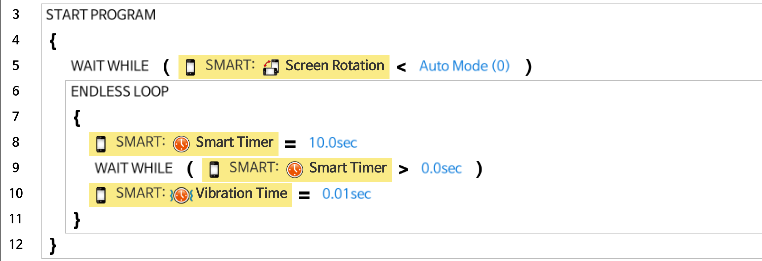
Vibration Time
Sets time to vibrate the smart device.
The following is an example of vibrating smart device for 1 second in every 10 seconds.
Vibration Status
Check if smart device is vibrating.
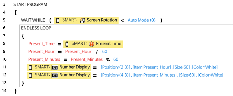
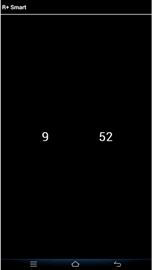
Present Time
Read the present time from smart device.
The following is an example of displaying current time on screen.
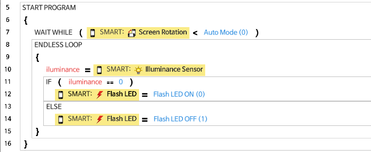
Flash LED
Controls the LED on smart device.
The following is an example of turning the LED on with the illuminance sensor value.
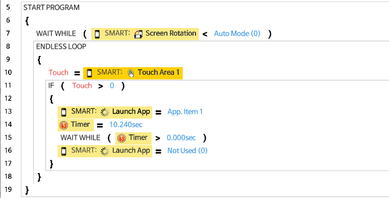
Launch App
Launch other app installed on the smart device.
The following is an example of running registered app when touching screen.
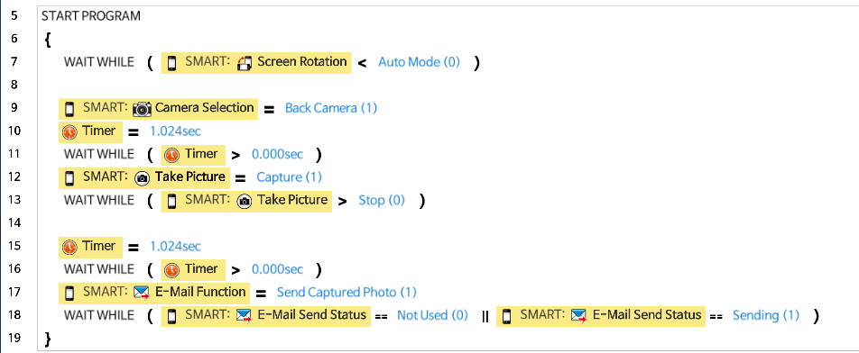
E-Mail Function
Send pictures or videos taken from the smart device via e-mail.
E-Mail Send Status
Check if e-mail is being delivered.
The following example shows how to use E-Mail function to send a picture.
Screen Width / Height
Gets the width and height of the smart device screen resolution.
SmartUserData
Access to a User Data area of the smart device for reading and writing user data.
Smart Device: Custom
- Access a specific memory area to read or write data.
- Write Byte(1 byte), Word(2 bytes), DWord(4 bytes) data on a specific address in smart device.
- Please refer to the control table of the app.
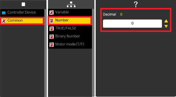
Common
Variables and constants can be manipulated.
Variable
- Variables are assigned in certain memory area of the program to read or write data.
-
The following is an example of using a variable.
Number
- Number can be used to assign a number in the code.
-
The valid value range is -2,147,483,648 ~ 4,294,967,295.
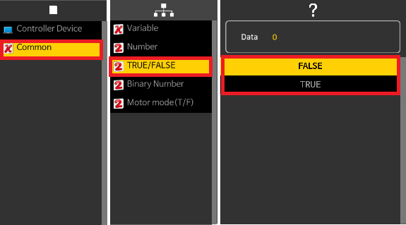
True/False
- Boolean expression can be used to assign a variable or to compare expression.
- True/False is useful when testing the conditional statments.
-
False: 0, True: 1.
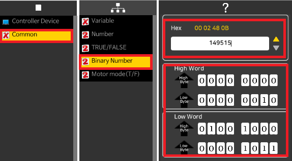
Binary Number
- Binary Number is useful to enter a binary value in the code.
- Binary Number can be used where bit operation is required.
-
The valid value range is 0 ~ 4,294,967,295 (Hex : 00 00 00 00 ~ FF FF FF FF).
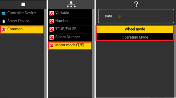
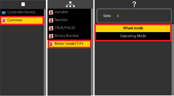
Motor Mode
This parameter is used to switch the SM-10 operating mode between Wheel mode and Joint mode.
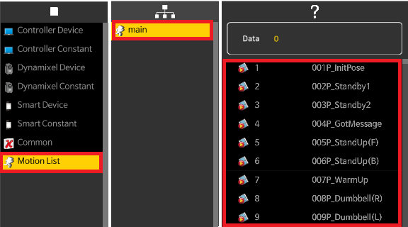
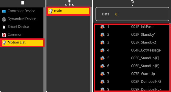
Motion List
If motion project is opened and avilable, the motion will be listed in this section.
Motion List menu will not be shown if motion example is not opened.