
NOTE: The OpenCR 1.0 e-Manual in Japanese (日本語) is available for the Japanese.
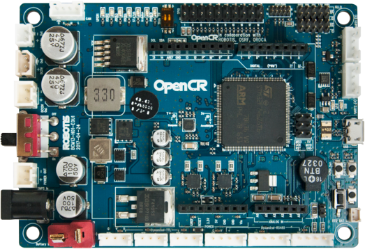
OpenCR 1.0
Introduction
OpenCR1.0 is developed for ROS embedded systems to provide completely open-source hardware and software.
Everything about the board; Schematics, PCB Gerber, BOM and the firmware source code for the TurtleBot3 and OP3 are free to distribute under open-source licenses for users and the ROS community.
The STM32F7 series chip inside the OpenCR1.0 board is based on a very powerful ARM Cortex-M7 with floating point unit.
The development environment for OpenCR1.0 is wide open from Arduino IDE and Scratch for young students to traditional firmware development for the expert.
Specifications
| Items | Specifications |
|---|---|
| Microcontroller | STM32F746ZGT6 / 32-bit ARM Cortex®-M7 with FPU (216MHz, 462DMIPS) Reference Manual, Datasheet |
| Sensors | (Discontinued) Gyroscope 3Axis, Accelerometer 3Axis, Magnetometer 3Axis (MPU9250) (New) 3-axis Gyroscope, 3-Axis Accelerometer, A Digital Motion Processor™ (ICM-20648) |
| Programmer | ARM Cortex 10pin JTAG/SWD connector USB Device Firmware Upgrade (DFU) Serial |
| Digital I/O | 32 pins (L 14, R 18) *Arduino connectivity 5Pin OLLO x 4 GPIO x 18 pins PWM x 6 I2C x 1 SPI x 1 |
| Analog INPUT | ADC Channels (Max 12bit) x 6 |
| Communication Ports | USB x 1 (Micro-B USB connector/USB 2.0/Host/Peripheral/OTG) TTL x 3 (B3B-EH-A / DYNAMIXEL) RS485 x 3 (B4B-EH-A / DYNAMIXEL) UART x 2 (20010WS-04) CAN x 1 (20010WS-04) |
| LEDs and buttons | LD2 (red/green) : USB communication User LED x 4 : LD3 (red), LD4 (green), LD5 (blue) User button x 2 Power LED : LD1 (red, 3.3 V power on) Reset button x 1 (for power reset of board) Power on/off switch x 1 |
| Input Power Sources | 5 V (USB VBUS), 5-24 V (Battery or SMPS) Default battery : LI-PO 11.1V 1,800mAh 19.98Wh Default SMPS : 12V 4.5A External battery Port for RTC (Real Time Clock) (Molex 53047-0210) |
| Input Power Fuse | 125V 10A LittleFuse 0453010 |
| Output Power Sources | *12V max 4.5A(SMW250-02)*5V max 4A(5267-02A), 3.3V@800mA(20010WS-02) |
| Dimensions | 105(W) X 75(D) mm |
| Weight | 60g |
* 5V power source is supplied from regulated 12V output. Total power consumption on 12V and 5V ports should not exceed 55W.
NOTE: MPU9250 sensor has been replaced with ICM-20648, since 2020, as MPU9250 is discontinued to produce.
NOTE : Hot swap power switch between “shore power”(12V, 4.5A SMPS) and “mobile power”(battery) from OpenCR1.0 board enables UPS(Uninterrupted Power Supply) feature.
![]()
DANGER
(Ignoring these warnings may cause serious injury or death)
- Never place items containing water, flammables/open flames, or solvents near the product.
- Never place fingers, arms, toes, and other body parts near product during operation.
- Cease operation and remove power from the product if the product begins to emit strange odors, noises, or smoke.
- Keep product out of reach of children.
- Check input polarity before installing or energizing wiring or cables.
![]()
CAUTION
(Ignoring these warnings may cause mild injury or damage to the product)
- Always comply with the product’s offical operating environment specifications including input voltage, current, and operating temperature.
- Do not insert blades or other sharp objects during product operation.
![]()
ATTENTION
(Ignoring these warnings may cause minor injury or damage to the product)
- Do not disassemble or modify the product.
- Do not drop the product or apply strong impacts.
- Do not connect or disconnect DYNAMIXEL cables while power is being supplied.
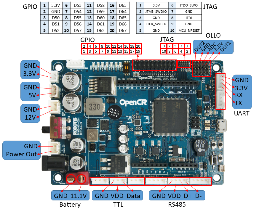
Layout/Pin Map
WARNING: To enhance user safety and to prevent proprietary risk or damage, be sure to check the pinout installed on DYNAMIXEL and the board. The Pinout of DYNAMIXEL may differ depending on a manufacturer of connector.
Arduino Connector
OpenCR includes a connector that is compatible with Arduino Uno pinmap.
The pins 0 to 21 are the same pin as the Arduino Uno, and thereafter they are mapped to the pins added to OpenCR.

| Pin No. | Function | 1 | 2 | 3 | etc |
|---|---|---|---|---|---|
| 0 | UART RXD | UART6_RX | FT |
||
| 1 | UART TXD | UART6 TX | FT |
||
| 2 | EXTI_0 | FT |
|||
| 3 | PWM | TIM3_CH1 | EXTI_1 | FT |
|
| 4 | EXTI_2 | FT |
|||
| 5 | PWM | TIM1_CH1 | FT |
||
| 6 | PWM | TIM2_CH3 | FT |
||
| 7 | EXTI_3 | FT |
|||
| 8 | EXTI_4 | FT |
|||
| 9 | PWM | TIM9_CH2 | FT |
||
| 10 | PWM/NSS | TIM11_CH1 | SPI2_NSS | FT |
|
| 11 | PWM/MOSI | TIM12_CH2 | SPI2_MOSI | FT |
|
| 12 | MISO | SPI2_MISO | FT |
||
| 13 | SCK | SPI2_SCK | FT |
||
| 14 | SDA | I2C1_SDA | FT |
||
| 15 | SCL | I2C1_SCL | FT |
||
| 16 | ADC | A0 | FT |
||
| 17 | ADC | A1 | FT |
||
| 18 | ADC | A2 | FT |
||
| 19 | ADC | A3 | FT |
||
| 20 | ADC | A4 | FT |
||
| 21 | ADC | A5 | FT |
FT pins are 5V tolerant except when in analog mode. The maximum injected current on FT pins are -5mA. Also total output current sunk / sourced by sum of all I/O pins are 120mA / -120mA respectively.
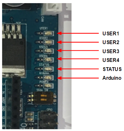
User LED
The OpenCR additional LEDs consist of four LEDs and are mapped to Arduino pin 22-25.
| Name | Arduino Pin | Pin Name |
|---|---|---|
| USER1 | 22 | BDPIN_LED_USER_1 |
| USER2 | 23 | BDPIN_LED_USER_2 |
| USER3 | 24 | BDPIN_LED_USER_3 |
| USER4 | 25 | BDPIN_LED_USER_4 |
| STS | 36 | BDPIN_LED_STATUS |
| Arduino | 13 | LED_BUILTIN |
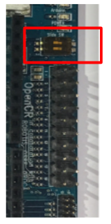
Dip Switch
| Arduino Pin | Pin Name |
|---|---|
| 26 | BDPIN_DIP_SW_1 |
| 27 | BDPIN_DIP_SW_2 |
GPIO
It has an 18-pin common GPIO expansion connector and is mapped to the GPIO pin of the Arduino. The pin number below is the arduino pin number.
| Pin Number | Arduino Pin | Pin Name | Pin Number | Arduino Pin | Pin Name | etc |
|---|---|---|---|---|---|---|
| 1 | - | 3.3V | 2 | - | GND | - |
| 3 | 50 | BDPIN_GPIO_1 | 4 | 51 | BDPIN_GPIO_2 | FT |
| 5 | 52 | BDPIN_GPIO_3 | 6 | 53 | BDPIN_GPIO_4 | FT |
| 7 | 54 | BDPIN_GPIO_5 | 8 | 55 | BDPIN_GPIO_6 | FT |
| 9 | 56 | BDPIN_GPIO_7 | 10 | 57 | BDPIN_GPIO_8 | FT |
| 11 | 58 | BDPIN_GPIO_9 | 12 | 59 | BDPIN_GPIO_10 | FT |
| 13 | 60 | BDPIN_GPIO_11 | 14 | 61 | BDPIN_GPIO_12 | FT |
| 15 | 62 | BDPIN_GPIO_13 | 16 | 63 | BDPIN_GPIO_14 | FT |
| 17 | 64 | BDPIN_GPIO_15 | 18 | 65 | BDPIN_GPIO_16 | FT |
| 19 | 66 | BDPIN_GPIO_17 | 20 | 67 | BDPIN_GPIO_18 | FT |
FT pins are 5V tolerant except when in analog mode. The maximum injected current on FT pins are -5mA. Also total output current sunk / sourced by sum of all I/O pins are 120mA / -120mA respectively.
NOTE : Typical pull-up / pull-down resistance is 40kΩ
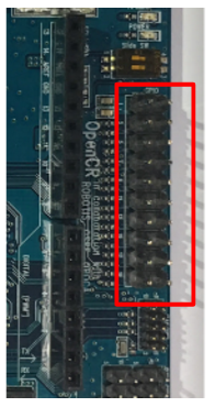
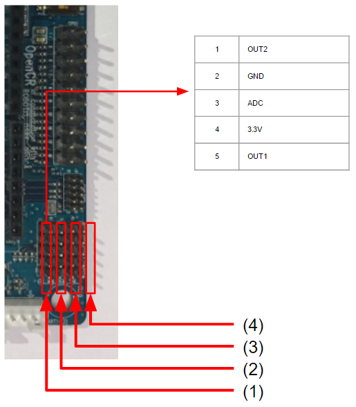
ROBOTIS 5-pin Connector
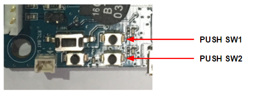
Push Switch
| Arduino Pin | Pin Name |
|---|---|
| 34 | BDPIN_PUSH_SW_1 |
| 35 | BDPIN_PUSH_SW_2 |
External Interrupt
External interrupts are assigned to the following pins and can be used with attachInterrupt(EXTI_Pin, callbackFunction, Mode) macro.
| EXTI Pin | Arduino Pin | Pin Name |
|---|---|---|
| 0 | 2 | - |
| 1 | 3 | TIM3_CH1 |
| 2 | 4 | - |
| 3 | 7 | - |
| 4 | 8 | - |
| 5 | 42 | OLLO_P1_ADC |
| 6 | 45 | OLLO_P2_ADC |
| 7 | 72 | OLLO_P3_ADC |
| 8 | 75 | OLLO_P4_ADC |
/*
  EXTI_0 is assigned to Arduino PIN 2
*/
pinmode(2, INPUT_PULLDOWN); //set Arduino Pin 2 as input with pull-down
attachInterrupt(0, changeDirection_EXIT_0, RISING);

void changeDirection_EXIT_0(void){
  Serial.println("EXIT_Interrupt! 0");
}
UART(Serial)
| Class Instance | Arduino Pin | Hardware |
|---|---|---|
| Serial | USB | USB |
| Serial1 | 0(RX), 1(TX) | USART6 |
| Serial2 (SerialBT1) | UART1 | USART2 |
| Serial3 | DXL Port | USART3 |
| Serial4 (SerialBT2) | UART2 | UART8 |
CAUTION: Since Serial3 is used for DYNAMIXEL, its usage differs from other serial. (For more information, please refer to DYNAMIXELWorkbench.)
Pin Definition
extern const Pin2PortMapArray g_Pin2PortMapArray[]=
{
  {GPIOC, GPIO_PIN_7,   NULL,     NO_ADC        , NULL   ,   NO_PWM       , NO_EXTI },  // 0  UART6_RX
  {GPIOC, GPIO_PIN_6,   NULL,     NO_ADC        , NULL   ,   NO_PWM       , NO_EXTI },  // 1  UART6_TX
  {GPIOG, GPIO_PIN_6,   NULL,     NO_ADC        , NULL   ,   NO_PWM       , 0       },  // 2              EXTI_0
  {GPIOB, GPIO_PIN_4,   NULL,     NO_ADC        , &hTIM3 ,   TIM_CHANNEL_1, 1       },  // 3  TIM3_CH1    EXTI_1
  {GPIOG, GPIO_PIN_7,   NULL,     NO_ADC        , NULL   ,   NO_PWM       , 2       },  // 4              EXTI_2
  {GPIOA, GPIO_PIN_8,   NULL,     NO_ADC        , &hTIM1 ,   TIM_CHANNEL_1, NO_EXTI },  // 5  TIM1_CH1
  {GPIOA, GPIO_PIN_2,   NULL,     NO_ADC        , &hTIM2 ,   TIM_CHANNEL_3, NO_EXTI },  // 6  TIM2_CH3
  {GPIOC, GPIO_PIN_1,   NULL,     NO_ADC        , NULL   ,   NO_PWM       , 3       },  // 7              EXTI_3
  {GPIOC, GPIO_PIN_2,   NULL,     NO_ADC        , NULL   ,   NO_PWM       , 4       },  // 8              EXTI_4
  {GPIOA, GPIO_PIN_3,   NULL,     NO_ADC        , &hTIM9 ,   TIM_CHANNEL_2, NO_EXTI },  // 9  TIM9_CH2
  {GPIOB, GPIO_PIN_9,   NULL,     NO_ADC        , &hTIM11,   TIM_CHANNEL_1, NO_EXTI },  // 10 TIM11_CH1   SPI2_NSS
  {GPIOB, GPIO_PIN_15,  NULL,     NO_ADC        , &hTIM12,   TIM_CHANNEL_2, NO_EXTI },  // 11 TIM12_CH2   SPI2_MOSI
  {GPIOB, GPIO_PIN_14,  NULL,     NO_ADC        , NULL   ,   NO_PWM       , NO_EXTI },  // 12             SPI2_MISO
  {GPIOA, GPIO_PIN_9,   NULL,     NO_ADC        , NULL   ,   NO_PWM       , NO_EXTI },  // 13 LED         SPI2_SCK
  {GPIOB, GPIO_PIN_7,   NULL,     NO_ADC        , NULL   ,   NO_PWM       , NO_EXTI },  // 14             I2C1_SDA
  {GPIOB, GPIO_PIN_8,   NULL,     NO_ADC        , NULL   ,   NO_PWM       , NO_EXTI },  // 15             I2C1_SCL

  {GPIOA, GPIO_PIN_0,   &hADC3,   ADC_CHANNEL_0 , NULL   ,   NO_PWM       , NO_EXTI },  // 16 A0
  {GPIOF, GPIO_PIN_10,  &hADC3,   ADC_CHANNEL_8 , NULL   ,   NO_PWM       , NO_EXTI },  // 17 A1
  {GPIOF, GPIO_PIN_9,   &hADC3,   ADC_CHANNEL_7 , NULL   ,   NO_PWM       , NO_EXTI },  // 18 A2
  {GPIOF, GPIO_PIN_8,   &hADC3,   ADC_CHANNEL_6 , NULL   ,   NO_PWM       , NO_EXTI },  // 19 A3
  {GPIOF, GPIO_PIN_7,   &hADC3,   ADC_CHANNEL_5 , NULL   ,   NO_PWM       , NO_EXTI },  // 20 A4
  {GPIOF, GPIO_PIN_6,   &hADC3,   ADC_CHANNEL_4 , NULL   ,   NO_PWM       , NO_EXTI },  // 21 A5

  {GPIOG, GPIO_PIN_12,  NULL,     NO_ADC        , NULL   ,   NO_PWM       , NO_EXTI },  // 22 BDPIN_LED_USER_1
  {GPIOE, GPIO_PIN_5,   NULL,     NO_ADC        , NULL   ,   NO_PWM       , NO_EXTI },  // 23 BDPIN_LED_USER_2
  {GPIOE, GPIO_PIN_4,   NULL,     NO_ADC        , NULL   ,   NO_PWM       , NO_EXTI },  // 24 BDPIN_LED_USER_3
  {GPIOG, GPIO_PIN_10,  NULL,     NO_ADC        , NULL   ,   NO_PWM       , NO_EXTI },  // 25 BDPIN_LED_USER_4
  {GPIOG, GPIO_PIN_11,  NULL,     NO_ADC        , NULL   ,   NO_PWM       , NO_EXTI },  // 26 BDPIN_DIP_SW_1
  {GPIOE, GPIO_PIN_6,   NULL,     NO_ADC        , NULL   ,   NO_PWM       , NO_EXTI },  // 27 BDPIN_DIP_SW_2
  {GPIOA, GPIO_PIN_4,   NULL,     NO_ADC        , NULL   ,   NO_PWM       , NO_EXTI },  // 28 BDPIN_SPI_CS_IMU
  {GPIOC, GPIO_PIN_0,   &hADC3,   ADC_CHANNEL_10, NULL   ,   NO_PWM       , NO_EXTI },  // 29 BDPIN_BAT_PWR_ADC
  {GPIOC, GPIO_PIN_3,   &hADC3,   ADC_CHANNEL_13, NULL   ,   NO_PWM       , NO_EXTI },  // 30
  {GPIOF, GPIO_PIN_14,  NULL,     NO_ADC        , NULL   ,   NO_PWM       , NO_EXTI },  // 31 BDPIN_BUZZER
  {GPIOF, GPIO_PIN_15,  NULL,     NO_ADC        , NULL   ,   NO_PWM       , NO_EXTI },  // 32 BDPIN_DXL_PWR_EN
  {GPIOG, GPIO_PIN_14,  NULL,     NO_ADC        , NULL   ,   NO_PWM       , NO_EXTI },  // 33
  {GPIOG, GPIO_PIN_3,   NULL,     NO_ADC        , NULL   ,   NO_PWM       , NO_EXTI },  // 34 BDPIN_PUSH_SW_1
  {GPIOC, GPIO_PIN_12,  NULL,     NO_ADC        , NULL   ,   NO_PWM       , NO_EXTI },  // 35 BDPIN_PUSH_SW_2
  {GPIOG, GPIO_PIN_9,   NULL,     NO_ADC        , NULL   ,   NO_PWM       , NO_EXTI },  // 36 BDPIN_LED_STATUS
  {GPIOA, GPIO_PIN_5,   NULL,     NO_ADC        , NULL   ,   NO_PWM       , NO_EXTI },  // 37 BDPIN_SPI_CLK_IMU
  {GPIOA, GPIO_PIN_6,   NULL,     NO_ADC        , NULL   ,   NO_PWM       , NO_EXTI },  // 38 BDPIN_SPI_SDO_IMU
  {GPIOB, GPIO_PIN_5,   NULL,     NO_ADC        , NULL   ,   NO_PWM       , NO_EXTI },  // 39 BDPIN_SPI_SDI_IMU

  {GPIOB, GPIO_PIN_0,   NULL,     NO_ADC        , NULL   ,   NO_PWM       , NO_EXTI },  // 40 OLLO_P1_SIG1
  {GPIOC, GPIO_PIN_8,   NULL,     NO_ADC        , NULL   ,   NO_PWM       , NO_EXTI },  // 41 OLLO_P1_SIG2
  {GPIOA, GPIO_PIN_7,   &hADC1,   ADC_CHANNEL_7 , NULL   ,   NO_PWM       , 5       },  // 42 OLLO_P1_ADC    EXTI_5
  {GPIOC, GPIO_PIN_5,   NULL,     NO_ADC        , NULL   ,   NO_PWM       , NO_EXTI },  // 43 OLLO_P2_SIG1
  {GPIOB, GPIO_PIN_1,   NULL,     NO_ADC        , NULL   ,   NO_PWM       , NO_EXTI },  // 44 OLLO_P2_SIG2
  {GPIOC, GPIO_PIN_4,   &hADC1,   ADC_CHANNEL_14, NULL   ,   NO_PWM       , 6       },  // 45 OLLO_P2_ADC    EXTI_6
  {GPIOD, GPIO_PIN_10,  NULL,     NO_ADC        , NULL   ,   NO_PWM       , NO_EXTI },  // 46 OLLO_SLEEP
  {GPIOF, GPIO_PIN_7,   NULL,     NO_ADC        , NULL   ,   NO_PWM       , NO_EXTI },  // 47
  {GPIOF, GPIO_PIN_7,   NULL,     NO_ADC        , NULL   ,   NO_PWM       , NO_EXTI },  // 48
  {GPIOF, GPIO_PIN_7,   NULL,     NO_ADC        , NULL   ,   NO_PWM       , NO_EXTI },  // 49

  {GPIOB, GPIO_PIN_10,  NULL,     NO_ADC        , NULL   ,   NO_PWM       , NO_EXTI },  // 50 BDPIN_GPIO_1
  {GPIOB, GPIO_PIN_11,  NULL,     NO_ADC        , NULL   ,   NO_PWM       , NO_EXTI },  // 51 BDPIN_GPIO_2
  {GPIOC, GPIO_PIN_13,  NULL,     NO_ADC        , NULL   ,   NO_PWM       , NO_EXTI },  // 52 BDPIN_GPIO_3
  {GPIOD, GPIO_PIN_2,   NULL,     NO_ADC        , NULL   ,   NO_PWM       , NO_EXTI },  // 53 BDPIN_GPIO_4
  {GPIOE, GPIO_PIN_3,   NULL,     NO_ADC        , NULL   ,   NO_PWM       , NO_EXTI },  // 54 BDPIN_GPIO_5
  {GPIOG, GPIO_PIN_2,   NULL,     NO_ADC        , NULL   ,   NO_PWM       , NO_EXTI },  // 55 BDPIN_GPIO_6
  {GPIOE, GPIO_PIN_10,  NULL,     NO_ADC        , NULL   ,   NO_PWM       , NO_EXTI },  // 56 BDPIN_GPIO_7
  {GPIOE, GPIO_PIN_11,  NULL,     NO_ADC        , NULL   ,   NO_PWM       , NO_EXTI },  // 57 BDPIN_GPIO_8
  {GPIOE, GPIO_PIN_12,  NULL,     NO_ADC        , NULL   ,   NO_PWM       , NO_EXTI },  // 58 BDPIN_GPIO_9
  {GPIOE, GPIO_PIN_13,  NULL,     NO_ADC        , NULL   ,   NO_PWM       , NO_EXTI },  // 59 BDPIN_GPIO_10
  {GPIOE, GPIO_PIN_14,  NULL,     NO_ADC        , NULL   ,   NO_PWM       , NO_EXTI },  // 60 BDPIN_GPIO_11
  {GPIOE, GPIO_PIN_15,  NULL,     NO_ADC        , NULL   ,   NO_PWM       , NO_EXTI },  // 61 BDPIN_GPIO_12
  {GPIOF, GPIO_PIN_0,   NULL,     NO_ADC        , NULL   ,   NO_PWM       , NO_EXTI },  // 62 BDPIN_GPIO_13
  {GPIOF, GPIO_PIN_1,   NULL,     NO_ADC        , NULL   ,   NO_PWM       , NO_EXTI },  // 63 BDPIN_GPIO_14
  {GPIOF, GPIO_PIN_2,   NULL,     NO_ADC        , NULL   ,   NO_PWM       , NO_EXTI },  // 64 BDPIN_GPIO_15
  {GPIOD, GPIO_PIN_8,   NULL,     NO_ADC        , NULL   ,   NO_PWM       , NO_EXTI },  // 65 BDPIN_GPIO_16
  {GPIOF, GPIO_PIN_4,   NULL,     NO_ADC        , NULL   ,   NO_PWM       , NO_EXTI },  // 66 BDPIN_GPIO_17
  {GPIOD, GPIO_PIN_9,   NULL,     NO_ADC        , NULL   ,   NO_PWM       , NO_EXTI },  // 67 BDPIN_GPIO_18
  {GPIOF, GPIO_PIN_7,   NULL,     NO_ADC        , NULL   ,   NO_PWM       , NO_EXTI },  // 68
  {GPIOF, GPIO_PIN_7,   NULL,     NO_ADC        , NULL   ,   NO_PWM       , NO_EXTI },  // 69

  {GPIOF, GPIO_PIN_12,  NULL,     NO_ADC        , NULL   ,   NO_PWM       , NO_EXTI },  // 70 OLLO_P3_SIG1
  {GPIOF, GPIO_PIN_11,  NULL,     NO_ADC        , NULL   ,   NO_PWM       , NO_EXTI },  // 71 OLLO_P3_SIG2
  {GPIOF, GPIO_PIN_5,   &hADC3,   ADC_CHANNEL_15, NULL   ,   NO_PWM       , 7       },  // 72 OLLO_P3_ADC    EXTI_7
  {GPIOE, GPIO_PIN_9,   NULL,     NO_ADC        , NULL   ,   NO_PWM       , NO_EXTI },  // 73 OLLO_P4_SIG1
  {GPIOE, GPIO_PIN_8,   NULL,     NO_ADC        , NULL   ,   NO_PWM       , NO_EXTI },  // 74 OLLO_P4_SIG2
  {GPIOF, GPIO_PIN_3,   &hADC3,   ADC_CHANNEL_9 , NULL   ,   NO_PWM       , 8       },  // 75 OLLO_P4_ADC    EXTI_8
  {GPIOF, GPIO_PIN_7,   NULL,     NO_ADC        , NULL   ,   NO_PWM       , NO_EXTI },  // 76
  {GPIOF, GPIO_PIN_7,   NULL,     NO_ADC        , NULL   ,   NO_PWM       , NO_EXTI },  // 77
  {GPIOF, GPIO_PIN_7,   NULL,     NO_ADC        , NULL   ,   NO_PWM       , NO_EXTI },  // 78
  {GPIOF, GPIO_PIN_7,   NULL,     NO_ADC        , NULL   ,   NO_PWM       , NO_EXTI },  // 79

  {GPIOD, GPIO_PIN_6,   NULL,     NO_ADC        , NULL   ,   NO_PWM       , NO_EXTI },  // 80 BDPIN_UART1_RX
  {GPIOD, GPIO_PIN_5,   NULL,     NO_ADC        , NULL   ,   NO_PWM       , NO_EXTI },  // 81 BDPIN_UART1_TX
  {GPIOE, GPIO_PIN_0,   NULL,     NO_ADC        , NULL   ,   NO_PWM       , NO_EXTI },  // 82 BDPIN_UART2_RX
  {GPIOE, GPIO_PIN_1,   NULL,     NO_ADC        , NULL   ,   NO_PWM       , NO_EXTI },  // 83 BDPIN_UART2_TX

  {NULL , 0          ,  NULL,     NO_ADC        , NULL   ,   NO_PWM       , NO_EXTI }
};
Arduino IDE
Install on Linux
USB Port Settings
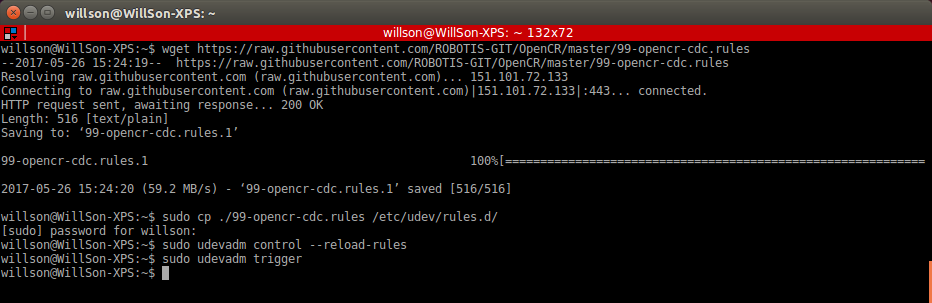
Make the OpenCR USB port be able to upload the Arduino IDE program without root permission.
$ wget https://raw.githubusercontent.com/ROBOTIS-GIT/OpenCR/master/99-opencr-cdc.rules
$ sudo cp ./99-opencr-cdc.rules /etc/udev/rules.d/
$ sudo udevadm control --reload-rules
$ sudo udevadm trigger
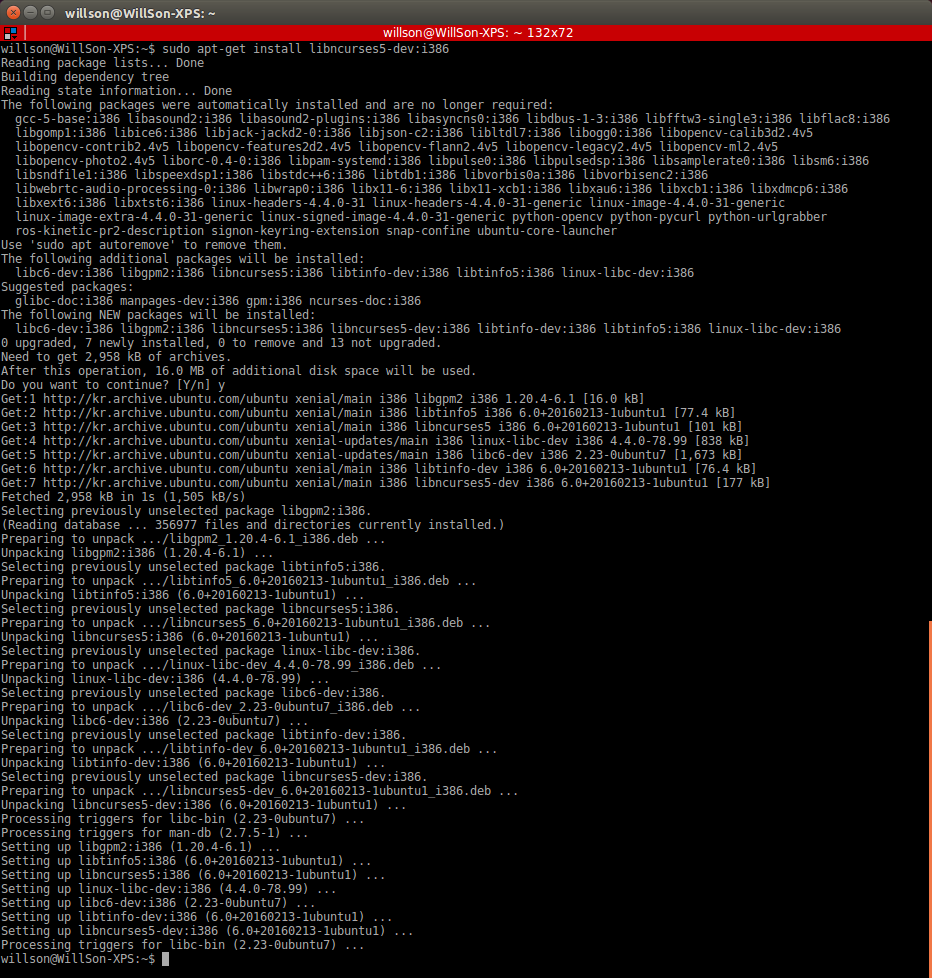
Compiler Settings
Since the OpenCR libraries is built for 32 bit platform, 64 bit PC needs the 32 bit compiler relevants for the ArduinoIDE.
$ sudo apt-get install libncurses5-dev:i386
Install Arduino IDE(Linux)
Download the latest version of Arduino IDE from the official arduino homepage, and install it. Currently, the OpenCR will be on service in the version 1.6.4 or later.
https://www.arduino.cc/en/Main/Software
Then, extract the downloaded file to the desired folder and execute the installation file from the terminal. In this case, the example shown below makes the folder tools in the user’s top folder (~/). This folder will act as the Arduino IDE folder.
$ cd ~/tools/arduino-1.6.4
$ ./install.sh
Set the file path of installed Arduino IDE as an absolute path named PATH in the bashrc file. Here recommends to use gedit editor. (Use another editor, if necessary.) Finally, source it to apply the changes.
$ gedit ~/.bashrc
$ export PATH=$PATH:$HOME/tools/arduino-1.6.4
$ source ~/.bashrc
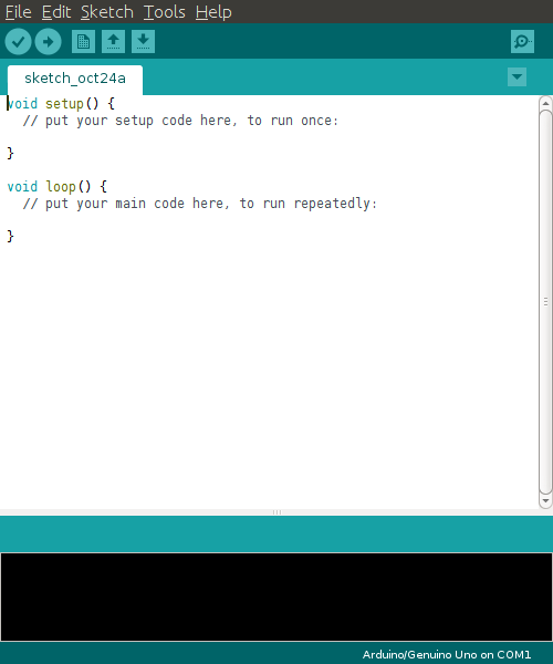
Run Arduino IDE(Linux)
To run the Arduino IDE on Linux platform, type into the terminal as follows.
$ arduino
Porting to Arduino IDE(Linux)
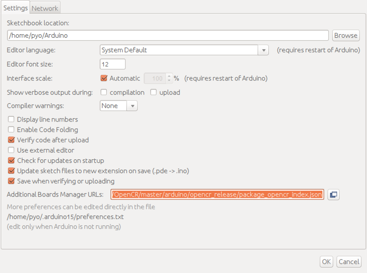
Preferences
After Arduino IDE is run, click File → Preferences in the top menu of the IDE. When the Preferences window appears, copy and paste following link to the Additional Boards Manager URLs textbox. (This step may take about 20 min.)
https://raw.githubusercontent.com/ROBOTIS-GIT/OpenCR/master/arduino/opencr_release/package_opencr_index.json
Install the OpenCR package via Boards Manager
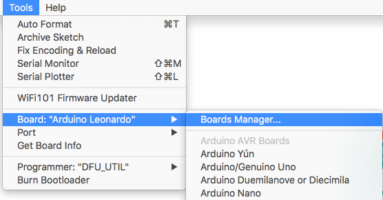
Click Tools → Board → Boards Manager.
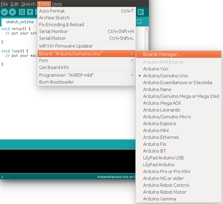
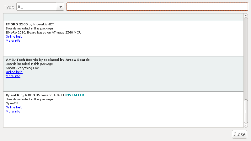
Type OpenCR into the textbox to find the OpenCR by ROBOTIS package. After it finds out, click Install.
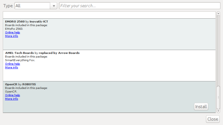
After the installation, “INSTALLED” will be appeared.
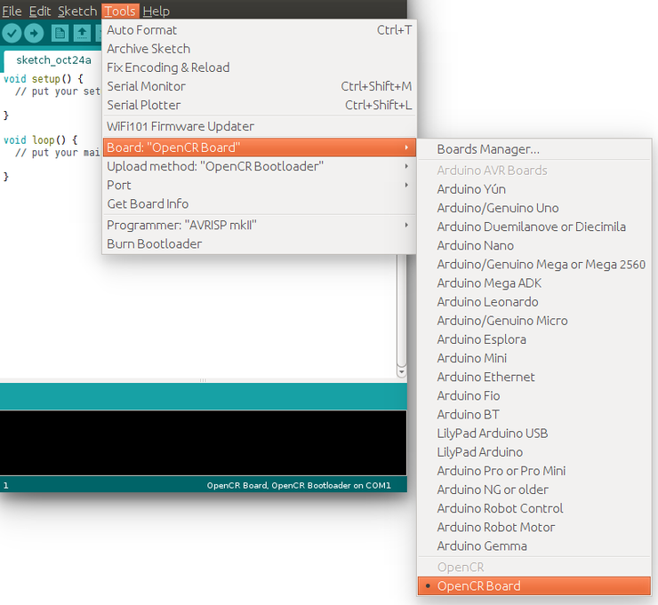
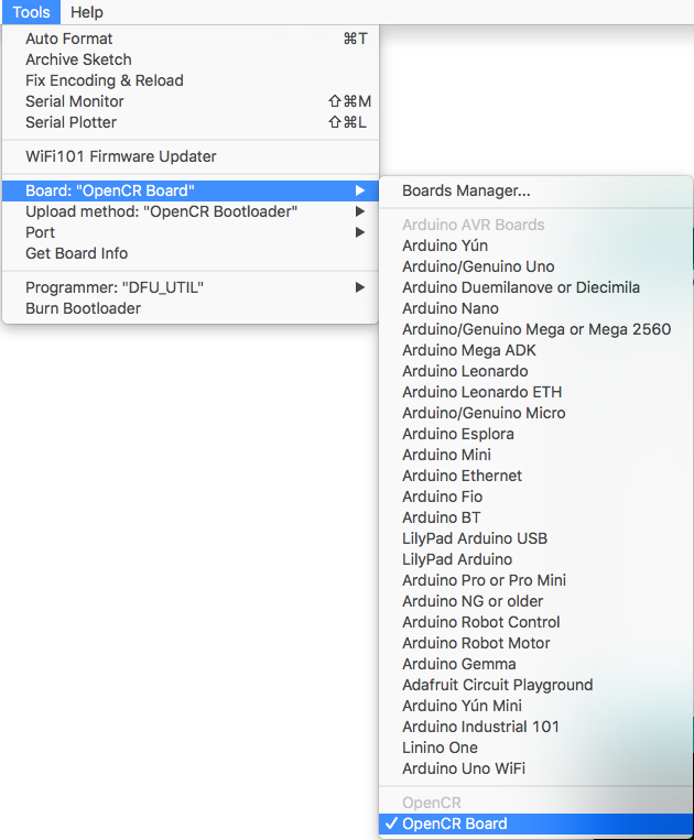
See if OpenCR Board is now on the list of Tools → Board. Click this to import the OpenCR Board source.
Port setting
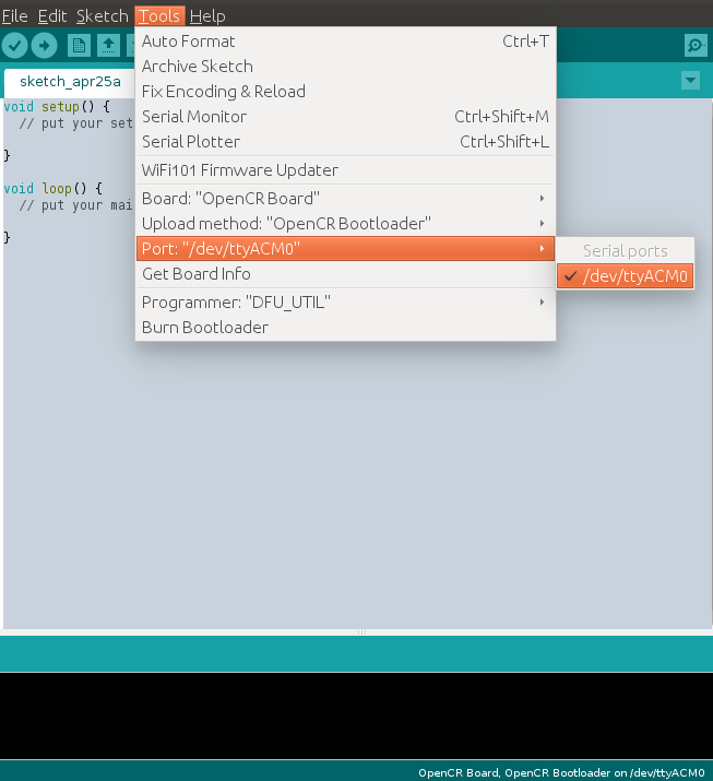
This step shows the port setting for the program uploads. The OpenCR should be connected to the PC and the OpenCR via the USB ports.
Select Tools → Port → /dev/ttyACM0.
WARNING : The last digit value 0 in the string /dev/ttyACM0 might be different depend on the USB connection environment.
Remove Modemmanager
After programming with the Arduino IDE and uploading the program to the OpenCR, the OpenCR will be restarted and be reconnected. At the same moment, the modem-related packages of the Linux will send the AT command to manage the device. Thus indicates an connection error on the OpenCR, so this step should be done previously.
$ sudo apt-get purge modemmanager
Install on Mac
Install Arduino IDE(Mac)
Download the latest version of Arduino IDE from the official arduino homepage, and install it. Currently, the OpenCR will be on service in the version 1.6.4 or later.
https://www.arduino.cc/en/Main/Software
Run Arduino IDE(Mac)
To run the Arduino IDE on Mac platform, click the Arduino IDE icon as follows.


Porting to Arduino IDE(Mac)
Preferences
After Arduino IDE is run, click File → Preferences in the top menu of the IDE. When the Preferences window appears, copy and paste following link to the Additional Boards Manager URLs textbox. (This step may take about 20 min.)
https://raw.githubusercontent.com/ROBOTIS-GIT/OpenCR/master/arduino/opencr_release/package_opencr_index.json

Install the OpenCR package via Boards Manager
Click Tools → Board → Boards Manager.
Type OpenCR into the textbox to find the OpenCR by ROBOTIS package. Install of the OpenCR package.
After the installation, “INSTALLED” will be appeared.
See if OpenCR Board is now on the list of Tools → Board. Click this to import the OpenCR Board source.
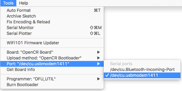
Port setting
This step shows the port setting for the program uploads. The OpenCR should be connected to the PC and the OpenCR via the USB ports.
Select Tools → Port → /dev/cu.usbmodem1411
CAUTION : The value of /dev/cu.usbmodem1411 may be different depending on the environment connected to the PC.
Install on Windows
Install Driver
WARNING : For Windows 10 PCs, please skip this driver installation.
Proper driver will be automatically installed.
To use OpenCR’s USB port as a serial port in Windows below 8.x, you need a USB CDC driver. You can install the USB driver provided by ST.
http://www.st.com/en/development-tools/stsw-stm32102.html
Install Arduino IDE(Windows)
Download the latest version of Arduino IDE from the official arduino homepage, and install it. Currently, the OpenCR will be on service in the version 1.6.4 or later.
https://www.arduino.cc/en/Main/Software
The Arduino IDE for Windows is available as an installation version and a compressed version, so you can install it using your preferred method.
Porting to Arduino IDE(Windows)
Preferences
After Arduino IDE is run, click File → Preferences in the top menu of the IDE. When the Preferences window appears, copy and paste following link to the Additional Boards Manager URLs textbox. (This step may take about 20 min.)
https://raw.githubusercontent.com/ROBOTIS-GIT/OpenCR/master/arduino/opencr_release/package_opencr_index.json
Install the OpenCR package via Boards Manager
- Click Tools → Board → Boards Manager.
- Type OpenCR into the textbox to find the OpenCR by ROBOTIS package. After it finds out, click Install.
- After the installation, “INSTALLED” will be appeared.
- See if OpenCR Board is now on the list of Tools → Board. Click this to import the OpenCR Board source.
Port setting
This step shows the port setting for the program uploads. The OpenCR should be connected to the PC and the OpenCR via the USB ports.
Select Tools → Port → COM1.
CAUTION : The value of COM1 may be different depending on the environment connected to the PC.
Examples
LED
It is a built-in LED test on the OpenCR board.
Code
There are 5 LEDs available in OpenCR, USER1 ~ 4, and the LED connected to base 13 of Arduino.
USER1 ~ 4 arduino pin numbers are defined as follows. When the corresponding pin is output as High / Low, the LED turns on / off.
#define BDPIN_LED_USER_1        22
#define BDPIN_LED_USER_2        23
#define BDPIN_LED_USER_3        24
#define BDPIN_LED_USER_4        25
It is a code that sequentially turns on and off all the LEDs.
int led_pin = 13;
int led_pin_user[4] = { BDPIN_LED_USER_1, BDPIN_LED_USER_2, BDPIN_LED_USER_3, BDPIN_LED_USER_4 };

void setup() {
  // Set up the built-in LED pin as an output:
  pinMode(led_pin, OUTPUT);
  pinMode(led_pin_user[0], OUTPUT);
  pinMode(led_pin_user[1], OUTPUT);
  pinMode(led_pin_user[2], OUTPUT);
  pinMode(led_pin_user[3], OUTPUT);
}

void loop() {
  int i;

  digitalWrite(led_pin, HIGH);  // set to as HIGH LED is turn-off
  delay(100);                   // Wait for 0.1 second
  digitalWrite(led_pin, LOW);   // set to as LOW LED is turn-on
  delay(100);                   // Wait for 0.1 second

  for( i=0; i<4; i++ )
  {
    digitalWrite(led_pin_user[i], HIGH);
    delay(100);
  }
  for( i=0; i<4; i++ )
  {
    digitalWrite(led_pin_user[i], LOW);
    delay(100);
  }
}
Result
Button
It is a built-in BUTTON test on the OpenCR board.
Code
There are Push switches SW1 ~ 2 and Dip switches 1 ~ 2 in OpenCR. The pin number is defined as below, so you can see the status of the current button when you input the data of that pin.
#define BDPIN_DIP_SW_1          26
#define BDPIN_DIP_SW_2          27
#define BDPIN_PUSH_SW_1         34
#define BDPIN_PUSH_SW_2         35
It is a code that outputs the button input status in serial.
void setup(){
  Serial.begin(115200);

  pinMode(BDPIN_DIP_SW_1, INPUT);
  pinMode(BDPIN_DIP_SW_2, INPUT);
  pinMode(BDPIN_PUSH_SW_1, INPUT);
  pinMode(BDPIN_PUSH_SW_2, INPUT);

}
void loop(){
  int dip_state;
  int push_state;

  dip_state  = digitalRead(BDPIN_DIP_SW_1)<<0;
  dip_state |= digitalRead(BDPIN_DIP_SW_2)<<1;

  push_state  = digitalRead(BDPIN_PUSH_SW_1)<<0;
  push_state |= digitalRead(BDPIN_PUSH_SW_2)<<1;

  Serial.print("dip_state = ");
  Serial.print(dip_state, BIN);

  Serial.print("\tpush_state = ");
  Serial.println(push_state, BIN);


  delay(100);
}
Result
Buzzer
It is a BUZZER related test built in the OpenCR board and uses the Tone function of Arduino.
Code
OpenCR has a built-in BUZZER, and the sound varies depending on the frequency. The built-in BUZZER is also mapped to the arduino pin number, and the arduino pin number is as follows. Arduino’s Tone function is ported, so you can use BUZZER by using this function.
#define BDPIN_BUZZER 31
It outputs the melody according to the scale defined in the pitches.h header. The following code is a change from OpenCR’s BUZZER to only the PIN number in the example provided in the Arduino IDE.
#include "pitches.h"

// notes in the melody:
int melody[] = {
  NOTE_C4, NOTE_G3, NOTE_G3, NOTE_A3, NOTE_G3, 0, NOTE_B3, NOTE_C4
};

// note durations: 4 = quarter note, 8 = eighth note, etc.:
int noteDurations[] = {
  4, 8, 8, 4, 4, 4, 4, 4
};

void setup() {
  // iterate over the notes of the melody:
  for (int thisNote = 0; thisNote < 8; thisNote++) {

    // to calculate the note duration, take one second
    // divided by the note type.
    //e.g. quarter note = 1000 / 4, eighth note = 1000/8, etc.
    int noteDuration = 1000 / noteDurations[thisNote];
    tone(BDPIN_BUZZER, melody[thisNote], noteDuration);

    // to distinguish the notes, set a minimum time between them.
    // the note's duration + 30% seems to work well:
    int pauseBetweenNotes = noteDuration * 1.30;
    delay(pauseBetweenNotes);
    // stop the tone playing:
    noTone(BDPIN_BUZZER);
  }
}
Result
PWM
This is the PWM output test from the Arundin pin of the OpenCR board.
Code
OpenCR has the same pin configuration as Arduino Uno. The PWM output is also mapped to the same port. Therefore, analogueWrite is used to output the PWM duty ratio to the corresponding ports. The resolution is 8 bits, from 0 to 255, and the frequency is 50 KHz.
This is an example of PWM output on all six pins.
int pwm_pins[6] = { 3, 5, 6, 9, 10, 11 };

void setup() {
  // put your setup code here, to run once:
}

void loop() {
  // put your main code here, to run repeatedly:
  int i;
  static uint8_t pwm_out = 0;

  for( i=0; i<6; i++ )
  {
    analogWrite(pwm_pins[i], pwm_out++);
  }
  delay(100);
}
Result
EEPROM
It is the EEPROM library test of OpenCR board.
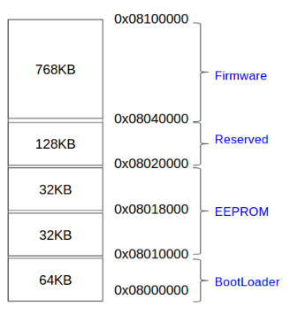
OpenCR does not have EEPROM memory, so it emulates a part of flash memory built in STM32F746 into EEPROM. The method of emulation was provided by ST as an example.
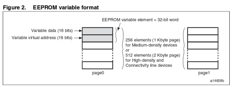
The area used as EEPROM is 0x08010000 ~ 0x08020000 as shown below. Two sectors are used.

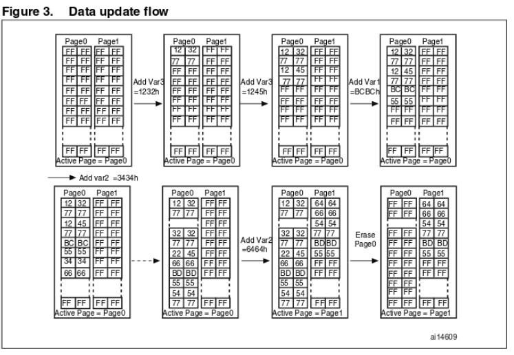
32 bits are used to store one data, the lower 16 bits are the data to be stored, and the upper 16 bits indicate the address of the corresponding data. When storing data, it is always stored in the new location. When you use one page while saving the data, only the latest values from the saved page are copied to the new page and the existing page is deleted. As a result, the number of flash memory erasures is reduced, thereby increasing the write-through life.
To use the EEPROM library, a header must be added, and the maximum size of the current EEPROM is 4 KBytes. Since the EEPROM library has ported what is supported in Arduino, the basic usage method is the same as that used in other existing Arduino boards. For more information on how to use it, please refer to the Adunion site.
https://www.arduino.cc/en/Reference/EEPROM
Code
#include <EEPROM.h>

void setup() {
  // put your setup code here, to run once:
  Serial.begin(115200);
}

void loop() {
  // put your main code here, to run repeatedly:
  uint32_t tTime;
  static int i = 0;


  if( (millis()-tTime) > 100 )
  {
    Serial.print(EEPROM.read(0));
    Serial.print("\t");
    Serial.print(EEPROM.read(1));
    Serial.print("\t");
    Serial.print(EEPROM.read(2));
    Serial.println("\t");

    tTime = millis();
  }

  if (Serial.available())
  {
    uint8_t inByte = Serial.read();

    if( inByte == '1' )
    {
      EEPROM.write(0, i+1);
      EEPROM.write(1, i+2);
      EEPROM.write(2, i+3);
      i++;
    }
  }
}
Result
OP3
OpenCR is used for power and sensor control in OP3, a humanoid robot. If the OpenCR firmware for OP3 has been changed, follow the procedure below to update it.
WARRNING : Please turn off the power switch before connecting power source(battery or SMPS) to the product.
Preparations
OpenCR develops and downloads firmware through the Arduino IDE. Therefore, you must install the Arduino IDE in advance and install the OpenCR board package. Install through the following link document.
Download OP3 firmware
-
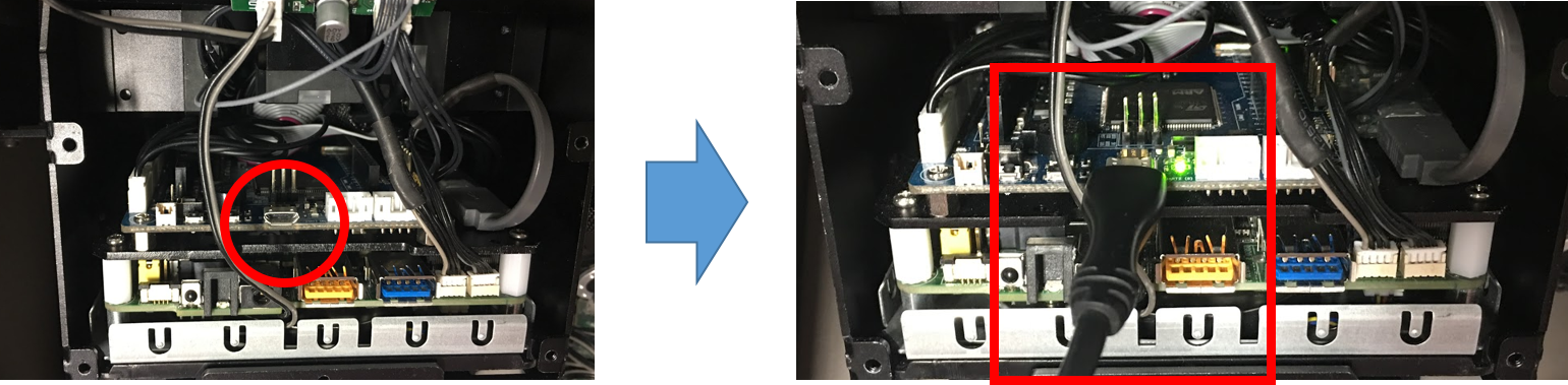
To update OpenCR’s firmware, open the front cover of OP3 and connect USB to PC as shown below.
- After connecting USB, select Tools-> Board-> OpenCR Board in Arduino IDE.
- Change Tools-> Port to the port to which the board is connected.
-
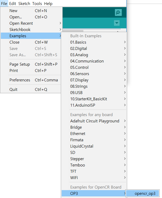
In the Arduino IDE Examples, select the firmware for OP3.
-
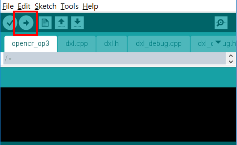
Click on the icon in the Arduino IDE that displays the red circle in the following figure to build and download the firmware. When the download is completed, the firmware is automatically executed.
Editing OP3 Firmware
The firmware that is provided as a basic example of OpenCR is read-only. If you want to edit it, you have to save it to a new folder and work on it.
-
Open the OP3 example.
-
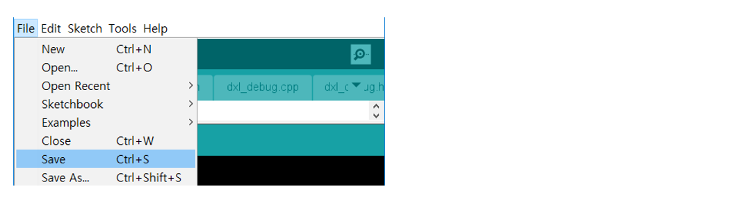
Select File-> Save.
-
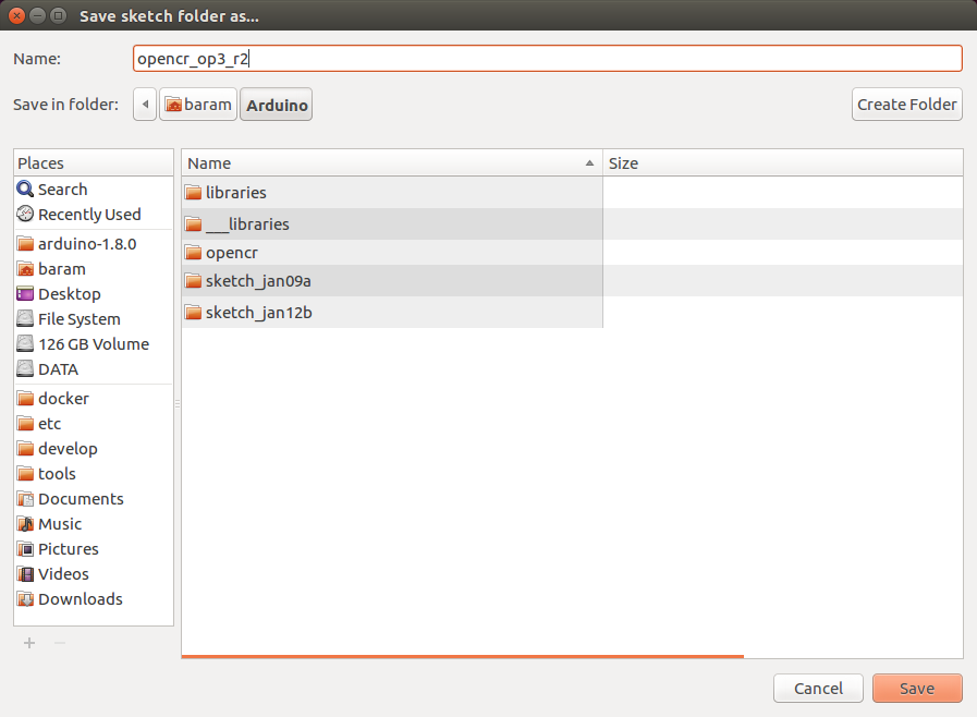
Since the example provided is Read-Only, select OK to save it as a new file.

-
Save it to a new folder and edit it. Once editing is complete, repeat the process of building and downloading the firmware.
Sensors
Ambient Light Sensor
It is ambient light sensor test on the OpenCR board.
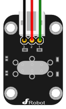
- Pinouts
- Green : Signal
- Red : Vcc
- Black : Gnd
- Specification
- ambient light sensor specification
- Supply Voltage : 3.3V to 5V
- Illumination range : 1 Lux to 6000 Lux
- Interface : Analog
Code
LED turns off/on sequentially depending on the light received by the sensor.
LED turns off in bright place. If it is dark place, the LED turns on.
This sensor is an analog sensor, connect it to port A0.
#define BDPIN_LED_USER_1     23
#define BDPIN_LED_USER_2     24
#define BDPIN_LED_USER_3     25
It is a code that turns on/off the LED depending on the brightness of light changes.
void setup()
{
  Serial.begin(9600);
  pinMode(BDPIN_LED_USER_1, OUTPUT);
  pinMode(BDPIN_LED_USER_2, OUTPUT);
  pinMode(BDPIN_LED_USER_3, OUTPUT);
}

void loop()
{
  if(analogRead(0)<200)
  {
    digitalWrite(BDPIN_LED_USER_1, LOW);
    digitalWrite(BDPIN_LED_USER_2, LOW);
    digitalWrite(BDPIN_LED_USER_3, LOW);
  }
  else if(analogRead(0)>200 && analogRead(0)<300)
  {
    digitalWrite(BDPIN_LED_USER_1, HIGH);
    digitalWrite(BDPIN_LED_USER_2, LOW);
    digitalWrite(BDPIN_LED_USER_3, LOW);
  }
  else if(analogRead(0)>300 && analogRead(0)<400)
  {
    digitalWrite(BDPIN_LED_USER_1, HIGH);
    digitalWrite(BDPIN_LED_USER_2, HIGH);
    digitalWrite(BDPIN_LED_USER_3, LOW);
  }
  else if(analogRead(0)>400 && analogRead(0)<500)
  {
    digitalWrite(BDPIN_LED_USER_1, HIGH);
    digitalWrite(BDPIN_LED_USER_2, HIGH);
    digitalWrite(BDPIN_LED_USER_3, HIGH);
  }
  Serial.println(analogRead(0), DEC);
  delay(100);
}
Result
Tilt Sensor
It is tilt sensor test on the OpenCR.
- Pinouts
- Green : Signal
- Red : Vcc
- Black : Gnd
- Specification
- Tilt Sensor Specification
- Supply Voltage : 3.3V to 5V
- Interface : Digital
Code
tilt sensor and led are connected to OpenCR. so that red/blue led is on/off when tilted and red/blue led is off/on when not tilted.
Connect the Tilt Sensor, Led_blue, and Led_red signal pins to D0, D1, and D2.
#define tilt     0
#define led_blue 1
#define led_red  2
void setup()
{
  pinMode(tilt, INPUT);
  pinMode(led_blue, OUTPUT);
  pinMode(led_red, OUTPUT);
}

void loop()
{
  if(digitalRead(tilt) == HIGH)
  {
    digitalWrite(led_blue, HIGH);
    digitalWrite(led_red, LOW);
  }
  else
  {
    digitalWrite(led_blue, LOW);
    digitalWrite(led_red, HIGH);
  }
}
Result
Rotation Sensor
It is rotation sensor test on the OpenCR board.
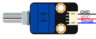
- Specification
- Rotation Sensor Specification
- Rotation Angle : 3600 degrees
- Supply Voltage : 3.3V to 5V
- Interface : Analog
Code
Rotation sensor is an analog sensor, the output value depending on the degree of rotation.
The LED turned on/off depending on the degree of rotation.
The signal pin is connected to A0 of OpenCR.
#define BDPIN_LED_USER_1        22
#define BDPIN_LED_USER_2        23
#define BDPIN_LED_USER_3        24
#define BDPIN_LED_USER_4        25
const int analogInPin = A0;
int sensorValue = 0;

void setup()
{
  Serial.begin(9600);
  pinMode(BDPIN_LED_USER_4, OUTPUT);
  pinMode(BDPIN_LED_USER_3, OUTPUT);
  pinMode(BDPIN_LED_USER_2, OUTPUT);
  pinMode(BDPIN_LED_USER_1, OUTPUT);
}

void loop()
{
  sensorValue = analogRead(analogInPin);
  Serial.print(" sensorValue : ");
  Serial.println(sensorValue);

  if(sensorValue>0 && sensorValue<50)
  {
    digitalWrite(BDPIN_LED_USER_4, LOW);
    digitalWrite(BDPIN_LED_USER_3, HIGH);
    digitalWrite(BDPIN_LED_USER_2, HIGH);
    digitalWrite(BDPIN_LED_USER_1, HIGH);
  }
  if(sensorValue>50 && sensorValue<100)
  {
    digitalWrite(BDPIN_LED_USER_4, LOW);
    digitalWrite(BDPIN_LED_USER_3, LOW);
    digitalWrite(BDPIN_LED_USER_2, HIGH);
    digitalWrite(BDPIN_LED_USER_1, HIGH);
  }
  if(sensorValue>100 && sensorValue<150)
  {
    digitalWrite(BDPIN_LED_USER_4, LOW);
    digitalWrite(BDPIN_LED_USER_3, LOW);
    digitalWrite(BDPIN_LED_USER_2, LOW);
    digitalWrite(BDPIN_LED_USER_1, HIGH);
  }
  if(sensorValue>200 && sensorValue<250)
  {
    digitalWrite(BDPIN_LED_USER_4, LOW);
    digitalWrite(BDPIN_LED_USER_3, LOW);
    digitalWrite(BDPIN_LED_USER_2, LOW);
    digitalWrite(BDPIN_LED_USER_1, LOW);
  }
  delay(100);
}
Result
Capacitive Touch Sensor
It is capacitive touch sensor test on the OpenCR board.
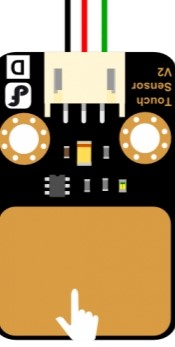
- Pinouts
- Green : Signal
- Red : Vcc
- Black : Gnd
- Specification
- Capacitive Touch Sensor Specification
- Supply Voltage : 3.3V to 5V
- Interface : Digital
Code
When you put your hand on the sensor, the led turn on/off sequentially and then the LED turns off when you take your hand.
Tilt sensor is a digital sensor, signal of sensor is connected to D0 of OpenCR.
#define SensorINPUT             0
#define BDPIN_LED_USER_1        22
#define BDPIN_LED_USER_2        23
#define BDPIN_LED_USER_3        24
#define BDPIN_LED_USER_4        25
int LED[] = {BDPIN_LED_USER_1, BDPIN_LED_USER_2, BDPIN_LED_USER_3, BDPIN_LED_USER_4};
int i = 0;

void setup()
{
  pinMode(SensorINPUT, INPUT);
  pinMode(BDPIN_LED_USER_1, OUTPUT);
  pinMode(BDPIN_LED_USER_2, OUTPUT);
  pinMode(BDPIN_LED_USER_3, OUTPUT);
  pinMode(BDPIN_LED_USER_4, OUTPUT);
}

void loop()
{
  if (digitalRead(SensorINPUT) == HIGH )
  {
    for(i=0; i<4; i++)
    {
      digitalWrite(LED[i], LOW);
      delay(100);
      digitalWrite(LED[i], HIGH);
    }
  }
  if (digitalRead(SensorINPUT) == LOW )
  {
    for(i=0; i<4; i++)
    {
      digitalWrite(LED[i], HIGH);
    }
  }
}
Result
Flame Sensor
It is flame sensor test on the OpenCR board.
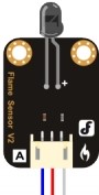
- Pinouts
- Blue : Signal
- Red : Vcc
- Black : Gnd
- Specification
- Flame Sensor Specification
- Detection range : 20cm(4.8V) ~ 100cm(1V)
- Supply Voltage : 3.3V to 5V
- Interface : Analog
Code
If the flame is detected, turns on the led.
Fire near the sensor, it outputs a high value close to 1024.
If the output exceeds 800, led will turn on.
Signal is connected to A0 of Arduino.
#define BDPIN_LED_USER_1 22
#define flame            0
void setup()
{
  Serial.begin(9600);
  pinMode(BDPIN_LED_USER_1, OUTPUT);
}

void loop()
{
  int val;
  val=analogRead(flame);

  if(val>800)
  {
    digitalWrite(BDPIN_LED_USER_1, LOW);
  }
  else
  {
    digitalWrite(BDPIN_LED_USER_1, HIGH);
  }

  Serial.println(val,DEC);
  delay(100);
}
Result
Joystic Sensor
It is joystic test on the OpenCR board.

- Specification
- Joystic Sensor Specification
- Interface : Analog
Code
Joystic is to get the output value according to the input.
We will look at the X Y Z values that change depending on how we move.
Signal of x,y and z is connected to A0, A1, A2 of Arduino.
#define X A0
#define Y A1
#define Z A2
void setup()
{
  Serial.begin(9600);
}
void loop()
{
  int x,y,z;
  x=analogRead(X);
  y=analogRead(Y);
  z=analogRead(Z);
.
  Serial.print(" X = ");
  Serial.print(x,DEC);

  Serial.print(" Y = ");
  Serial.print(y,DEC);

  Serial.print(" Z = ");
  Serial.println(z,DEC);
  delay(100);
}
Result
DYNAMIXEL Workbench
OpenMANIPULATOR
Bootloader
The bootloader is responsible for initializing the board and downloading and executing the firmware into flash memory.
The STM32F7xx, which is used for the main MCU on the OpenCR board, supports DFU(Device Firmware Upgrade).
This enables the built-in bootloader of the MCU by itself to boot the DFU protocol by using USB, primarily for the bootloader initialization, the recovery mode, and the bootloader update.
The biggest advantage to let the users be able to use bootloader with USB but no other JTAG equipment.
Write the firmware by using the DFU mode which is embedded in MCU without writing / debugging equipment, such as STLink.
| Item | Description |
|---|---|
| Supported OS | Windows, Linux, Mac |
| Compiler | gcc arm 5.4 2016q2 |
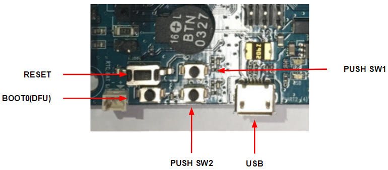
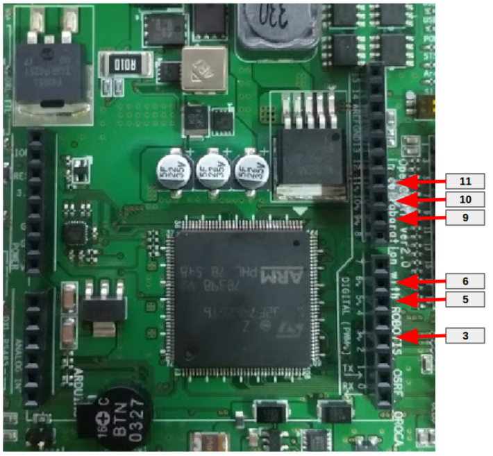
- USB Port
- Connected to PC and recognized as serial port
- A communication cable for downloading firmware through the bootloader.
- PUSH SW2
- Press and hold the button when the power is on or reset to execute the bootloader
- If the button is not pressed when the power is turned on, the bootloader is executed. If the firmware is in the flash memory, the bootloader executes the firmware.
Memory Map
The STM32F746 used in OpenCR has an internal flash memory of 1024KB, and each area is defined as follows. The bootloader is located at the lowest address in the flash memory and the bootloader is first executed when the power is turned on and reset.
Boot Sequence
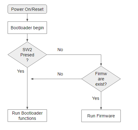
If the board is powered on or reset, if the SW2 button is pressed, it waits for commands from the PC in the boot loader state. If the SW2 button is not pressed, jump to the firmware if the firmware exists in the firmware area of the flash memory and execute it.
Communication Protocol
MavLink
The communication protocol for downloading firmware from the boot loader uses MavLink. MavLink was created for communication in UAV, see the link below for details.
As a feature, when the command name and parameters are generated as an xml file, the communication code for each command is automatically generated by the code such as java / c / python. It creates a function that performs CRC checking or data parsing for communication automatically, so if you define only necessary commands as xml file, you can generate the source automatically.
It is also easy to port because it generates in various languages.
http://qgroundcontrol.org/mavlink/start
Composition of Commands
<?xml version="1.0"?>
<mavlink>
        <!--<include>common.xml</include>-->
        <!-- NOTE: If the included file already contains a version tag, remove the version tag here, else uncomment to enable. -->
<!--<version>3</version>-->
<enums>
</enums>
<messages>
 <message id="150" name="ACK">
  <description></description>
  <field type="uint8_t"    name="msg_id"></field>
  <field type="uint16_t"   name="err_code"></field>
  <field type="uint8_t"    name="length"></field>
  <field type="uint8_t[16]" name="data"></field>
 </message>
</messages>
      ... omit ...
</mavlink>
The final defined xml file is added to github.
https://github.com/ROBOTIS-GIT/OpenCR/blob/master/arduino/opencr_bootloader/common/msg/xml/opencr_msg
The defined xml file should be converted to the command code of the language you want to use through the MavLink utility. Download the MavLink utility source code from github below.
https://github.com/mavlink/mavlink/
It is written in Python and requires Python 2.7 or later. If it is not installed, add it.
$ sudo apt-get install python-tk
$ sudo apt-get install python-future
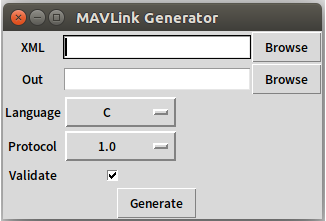
$ python mavgenerate.py
When you run MAVLink Generator, a GUI screen will appear, select the XML file already created in XML, set the language to C, and set the protocol version to 1.0. If you select the folder name for output in Out, and select Generate, a function header file that can use the command added based on the xml file is created and can be used in the firmware
The final generated communication code can be seen in the link below.
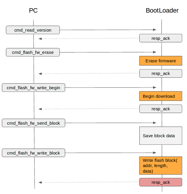
The commands for the boot loader to download and execute the firmware through the MavLink protocol are as follows.
void cmd_read_version( msg_t *p_msg );
void cmd_read_board_name( msg_t *p_msg );
void cmd_jump_to_fw( msg_t *p_msg );
void cmd_flash_fw_write_packet( msg_t *p_msg );
void cmd_flash_fw_write_begin( msg_t *p_msg );
void cmd_flash_fw_write_end( msg_t *p_msg );
void cmd_flash_fw_write_block( msg_t *p_msg );
void cmd_flash_fw_erase( msg_t *p_msg );
void cmd_flash_fw_verify( msg_t *p_msg );
void cmd_flash_fw_read_block( msg_t *p_msg );
Download Sequence
The main function of the boot loader is to receive the firmware file from the PC, store it in flash, and execute the stored firmware. The order of downloading is as follows, and you can check how to proceed and how to proceed by looking at it. You can do the actual implementation based on this.
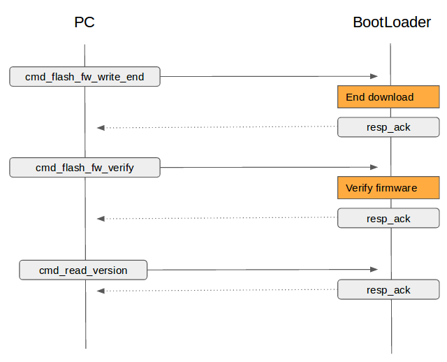
Message Processing
In the code actually implemented, the main function calls the msg_process_vcp() function for message processing. In this case, if there is data coming from USB, msg_recv function is called to parse the message, and if any command is received, it returns TRUE to call the corresponding command function.
int main(void)
{
  tTime = millis();
  while(1)
  {
    msg_process_vcp();
  }
}

void msg_process_vcp(void)
{
  BOOL ret;
  uint8_t ch;
  msg_t msg;


  while(vcp_is_available())
  {
    ch = vcp_getch();
    ret = msg_recv( 0, ch, &msg );

    if( ret == TRUE )
    {
      switch( msg.p_msg->msgid )
      {
        case MAVLINK_MSG_ID_READ_VERSION:
          cmd_read_version(&msg);
          break;

        case MAVLINK_MSG_ID_READ_BOARD_NAME:
          cmd_read_board_name(&msg);
          break;

        ... omit ...

       default:
         cmd_send_error(&msg, ERR_INVALID_CMD);
         break;
      }
    }
  }
}
For example, the Mavlink_msg_read_version_decode() function parses the message data into the data structure of the command. If the field Responsive to parsed mav_data is active, it sends the boot loader version and revision via the ACK command.
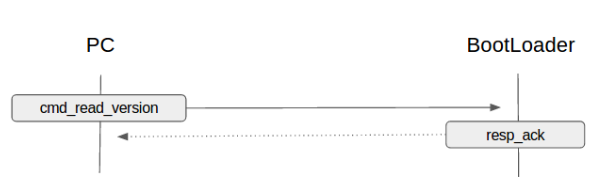
void cmd_read_version( msg_t *p_msg )
{
  err_code_t err_code = OK;
  mavlink_ack_t     mav_ack;
  mavlink_read_version_t mav_data;


  mavlink_msg_read_version_decode(p_msg->p_msg, &mav_data);


  if( mav_data.resp == 1 )
  {
    mav_ack.msg_id   = p_msg->p_msg->msgid;
    mav_ack.err_code = err_code;
    mav_ack.data[0] = boot_version;
    mav_ack.data[1] = boot_version>>8;
    mav_ack.data[2] = boot_version>>16;
    mav_ack.data[3] = boot_version>>24;
    mav_ack.data[4] = boot_revision;
    mav_ack.data[5] = boot_revision>>8;
    mav_ack.data[6] = boot_revision>>16;
    mav_ack.data[7] = boot_revision>>24;
    mav_ack.length  = 8;
    resp_ack(p_msg->ch, &mav_ack);
  }
}
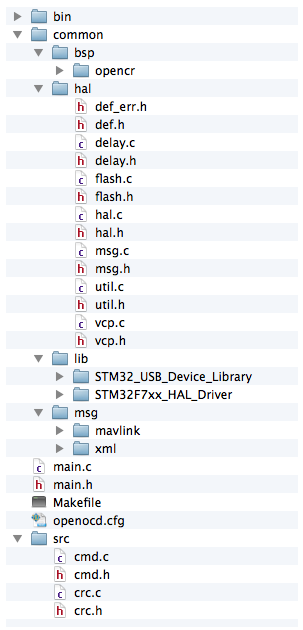
Folder Structure
| Item | Contents |
|---|---|
| bin | Save obj and bin files generated after build |
| common->bsp | Includes board-specific functions (LED / BUTTON / USB, etc.) |
| common->hal | Hardware independent function folders on the board |
| common->lib | Libraries used externally or publicly |
| msg->mavlink | Communication protocol source generated by Xml |
| msg->xml | The xml file folder where you defined the command |
| src | Function folder required for boot loader function |
Update Bootloader
You can update the bootloader using the MCU’s DFU mode on the OpenCR board.
To update using DFU mode, you need to install dfu-util.
$ sudo apt-get install dfu-util
Enter DFU Mode
To run OpenCR in DFU mode, please follow the instruction below.
- Hold down the
Bootbutton. - Press the
Resetbutton. - Release the
Resetbutton. - Release the
Bootbutton.
OpenCR will enter the DFU mode after reset by the built-in boot loader.
Check Boot Mode
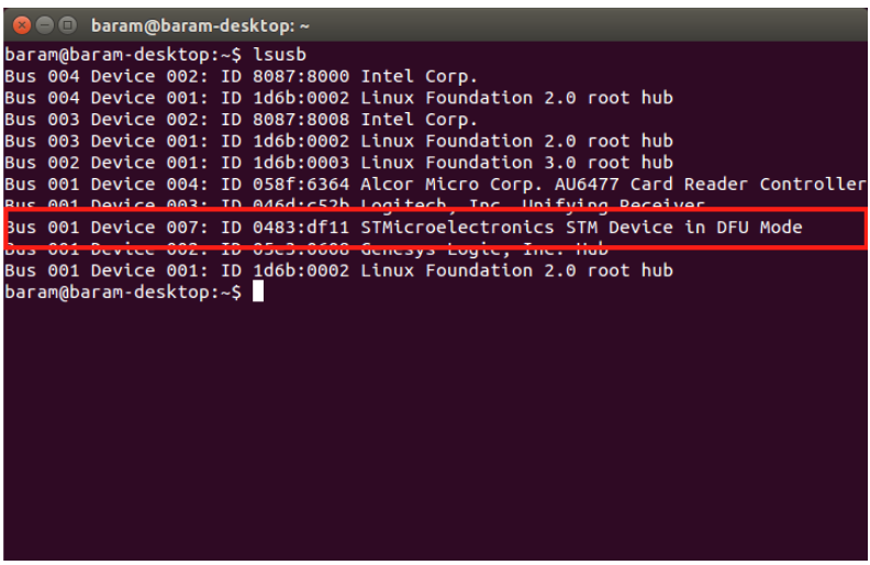
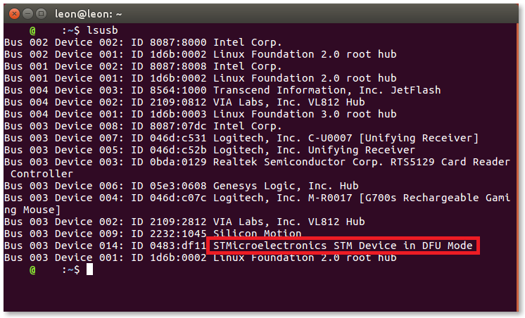
For Linux
If you run lsusb, you can check if it is in DFU mode. If the MCU is in DFU mode, the DFU device will be displayed after running lsusb.
$ lsusb
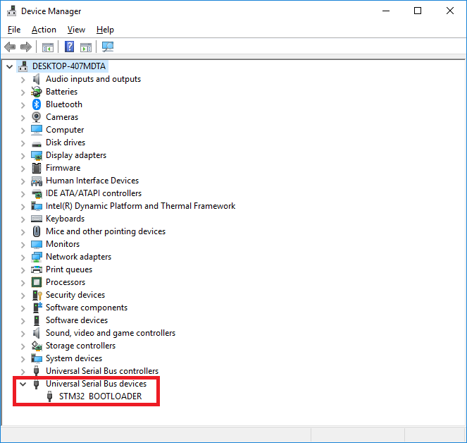
For Windows
Open the Device Manager > Universal Serial Bus Devices and see if STM32 BOOTLOADER is detected.
If not, please refer to Driver Install(Optional) section.
Burn Bootloader
Burn Bootloader(Linux)
CAUTION : Update the bootloader if version has been updated.
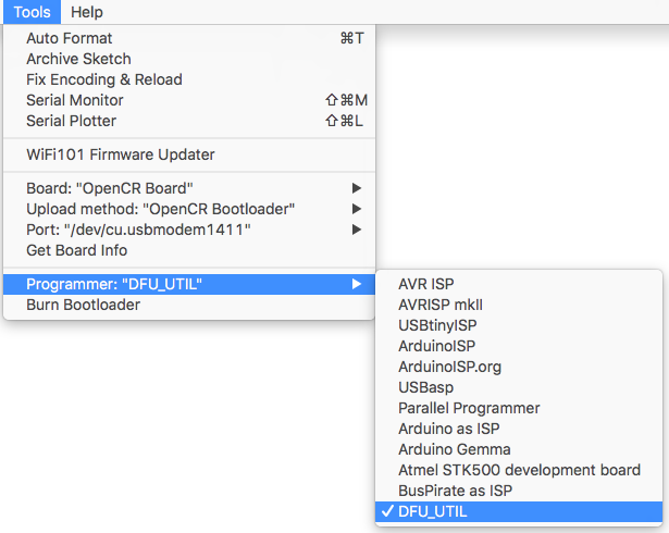
Programmer Setting
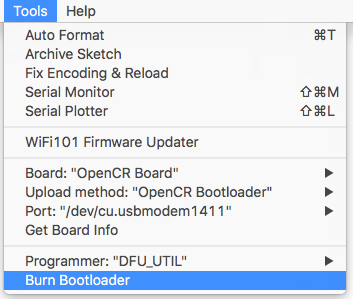
Select Tools → DFU-UTIL
Run DFU mode.
Press the Reset Button while the Boot Button is being pushed. This activates the DFU mode.
If you successfully entered to DFU mode, you will be able to find STMicroelectronics STM Device in DFU Mode text string when lsusb is entered in the terminal.
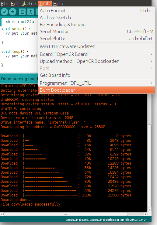
Download Bootloader.
Click Tools → Burn Bootloader to download the bootloader.
Burn Bootloader(Mac)
CAUTION : Update the bootloader if version has been updated.
Programmer Setting
Select Tools → DFU-UTIL
Run DFU Mode
Press the Reset Button while the Boot Button is being pushed. This activates the DFU mode.
Download Bootloader
Click Tools → Burn Bootloader to download the bootloader.
Burn Bootloader(Windows)
CAUTION : Update the bootloader if version has been updated.
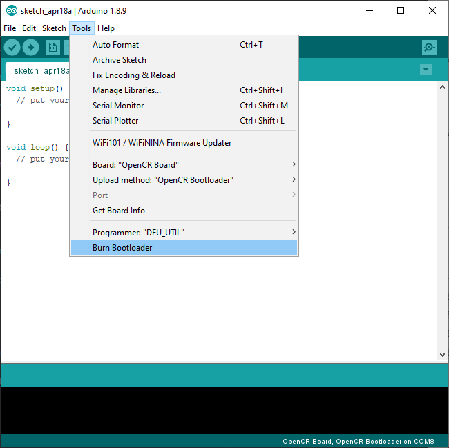
Run DFU Mode
Press the Reset Button while the Boot Button is being pushed. This activates the DFU mode.
Download Bootloader
After setting up the Arduino IDE, run Arduino IDE and go to Tools > Burn Bootloader to download the bootloader.
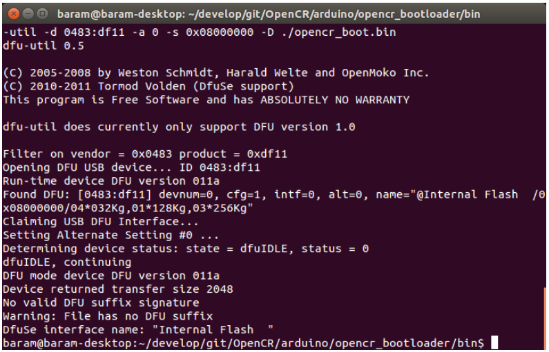
Custom Bootloader
If you have built a custom bootloader, move to the folder where the bin file is located and update it with dfu-util.
Below command is an example where opencr_boot.bin is placed at the root directory.
$ sudo dfu-util -d 0483:df11 -a 0 -s 0x08000000 -D ./opencr_boot.bin
Driver Install(Optional)
In order to perform Bootloader update, ST DFU driver has to be installed on your PC. In Windows 10, ST DFU driver is usually installed automatically.
However, if ST DFU driver is not properly installed, OpenCR will not be able to burn new bootloader in Arduino IDE.
When failing to burn the bootloader in Arduino IDE with below error message, please reinstall the DFU driver as described below.
Cannot open DFU device 0483:df11
No DFU capable USB device available
Error while burning bootloader.
Error Message from Arduino IDE while burning Bootloader.
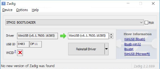
-
Download Zadig from http://zadig.akeo.ie/
-
Install and run Zadig.
-
Go to
Options>List All Devices.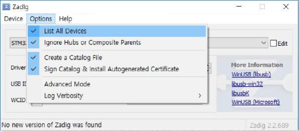
-
Select STM32 BOOTLOADER and install WinUSB driver.
Downloader
The PC Downloader application communicates with the boot loader and downloads the firmware from the PC to the firmware area of the OpenCR board flash.
The Downloader appends necessary information to the provided binary file.
| Item | Description |
|---|---|
| Supported OS | Windows, Linux, Mac |
| Compiler | Linux : gcc Windows : Qt 5.7 |
Description
Read the following description for use of the command to ensure proper use.
$ opencr_ld <Communication port> <Baudrate> <Firmware binary> <Firmware execution status [0|1]>
Communication port
- Type the name of the serial port in use (i.e,
/dev/ttyACM0is widely used for Linux.)
Baudrate
- The speed to communicate and input at 115,200 bps.
Firmware binary
- The firmware binary image has an extension of bin.
Firmware execution status
- Set
1to execute the downloaded firmware after download. -
Set
0(or not input status) to download the firmware.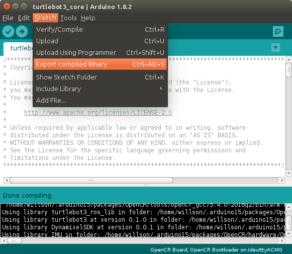
Exporting compiled binary file fron Arduino IDE
Example For Linux / Mac
The following is an example for Linux and Mac users. Be sure that the command may differ depending on your PC environment.
$ sudo opencr_ld /dev/ttyACM0 115200 ./opencrfw.bin 1
Communication port
- /dev/ttyACM0
Baudrate
- 115,200 bps.
Firmware binary
- opencrfw.bin
Firmware execution status
- 1
Example For Windows
The following is an example for Windows users. Be sure that the command may differ depending on your PC environment.
opencr_ld.exe COM1 115200 ./opencrfw.bin 1
Communication port
- COM1
Baudrate
- 115,200 bps.
Firmware binary
- opencrfw.bin
Firmware execution status
- 1
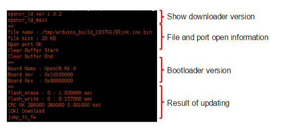
Execution Result
Download Executable File
Excutable file can be downloaded at the provided link.
Reference
Recovery Mode
If currupted or incompleted firmware is downloaded and the board freezes or does not work, you must enter a boot loader to be able to download the normal firmware. See Boot Sequence for more information.
To execute the boot loader, please follow the instruction below.
- Turn on the power of the OpenCR board.
- Hold down the
PUSH SW2button. - Press the
Resetbutton. - Release the
Resetbutton. - Release the
PUSH SW2button.
OpenCR will enter the boot loader after reset. When the boot loader is running, the STATUS LED blinks every 100ms.
You can download the normal firmware while the boot loader is running.
DYNAMIXEL Connectors
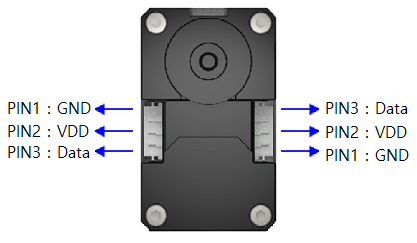
Following table refers the pinout of DYNAMIXEL.
| Item | TTL | RS-485 |
|---|---|---|
| Pinout | 1 GND2 VDD3 DATA |
1 GND2 VDD3 DATA+4 DATA- |
| Diagram |  |
 |
| Housing | 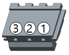 JST EHR-03 |
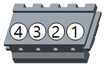 JST EHR-04 |
| PCB Header | 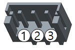 JST B3B-EH-A |
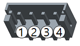 JST B4B-EH-A |
| Crimp Terminal | JST SEH-001T-P0.6 | JST SEH-001T-P0.6 |
| Wire Gauge for DYNAMIXEL | 21 AWG | 21 AWG |
Communication Circuit
To control the DYNAMIXEL actuators, the main controller needs to convert its UART signals to the half duplex type. The recommended circuit diagram for this is shown below.
TTL Communication
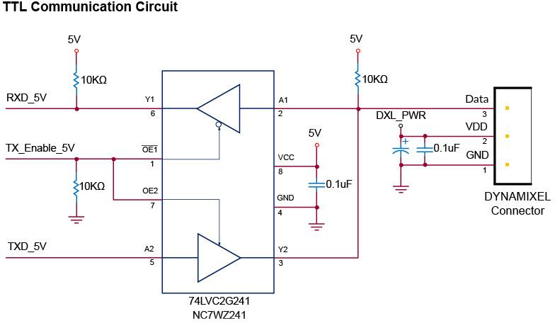
TTL Circuit
NOTE: Above circuit is designed for 5V or 5V tolerant MCU. Otherwise, use a Level Shifter to match the voltage of MCU.
RS-485 Communication
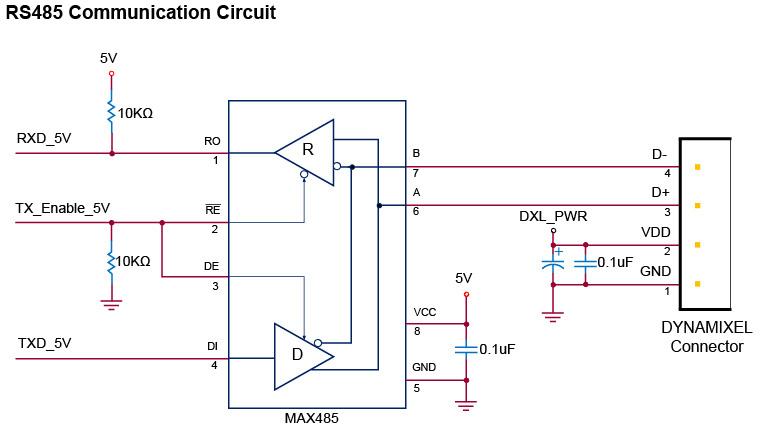
RS-485 Circuit
NOTE: Above circuit is designed for 5V or 5V tolerant MCU. Otherwise, use a Level Shifter to match the voltage of MCU.
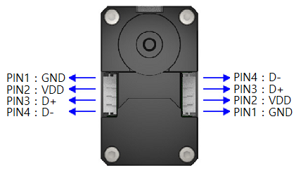
The power of DYNAMIXEL is supplied via Pin1(-), Pin2(+).
(The above circuit is built into DYNAMIXEL’s controller only)
In the above circuit diagram, the direction of data signal of TxD and RxD in the TTL Level is determined according to the level of DIRECTION 485 as follows:
In case of DIRECTION485 Level = High: The signal of TxD is output to D+ and D-
In case of DIRECTION485 Level = Low: The signal of D+ and D- is output to RxD
Download
Certifications
Please inquire us for information regarding unlisted certifications.
FCC
Note: This equipment has been tested and found to comply with the limits for a Class A digital device, pursuant to part 15 of the FCC Rules. These limits are designed to provide reasonable protection against harmful interference when the equipment is operated in a commercial environment. This equipment generates, uses, and can radiate radio frequency energy and, if not installed and used in accordance with the instruction manual, may cause harmful interference to radio communications. Operation of this equipment in a residential area is likely to cause harmful interference in which case the user will be required to correct the interference at his own expense.
WARNING
Any changes or modifications not expressly approved by the manufacturer could void the user’s authority to operate
the equipment.