
Introduction
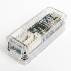
U2D2
U2D2 is a small size USB communication converter that enables to control and operate DYNAMIXEL with PC.
How to Use
NOTE: If U2D2 is unable to be detected by your computer, download the Virtual COM Port Driver to detect the FTDI devices such as the U2D2.
PC to DYNAMIXEL
U2D2 can be connected to the USB port of the PC with the enclosed USB cable.
It supports both 3Pin TTL connector and 4Pin RS-485 connector to link up with various DYNAMIXEL’s.
U2D2 does not supply power to DYNAMIXEL, therefore, an external power supply should provide power to DYNAMIXEL.
Be careful as recommended voltage for each DYNAMIXEL could be vary by model.
Please refer to e-Manual for recommended supply voltage and power connection with various power supplies.

PC to UART
U2D2 is able to connect ROBOTIS controllers that support 4Pin UART communication such as OpenCM9.04, CM-150 and CM-200 to the PC with the enclosed USB cable.
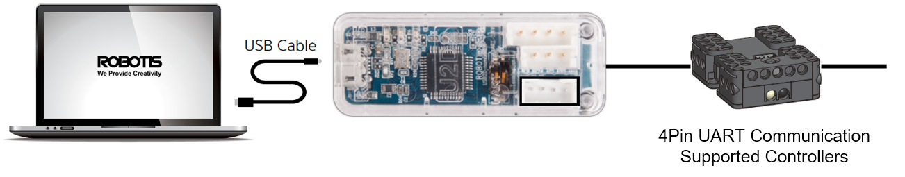
NOTE : In case of unstable communication with U2D2, check if there is a reference voltage difference in the communication. Please check PC and other devices are grounded properly. Failing to do so might cause damages on the U2D2.
Specifications
| Item | Description |
|---|---|
| Weight | 9g |
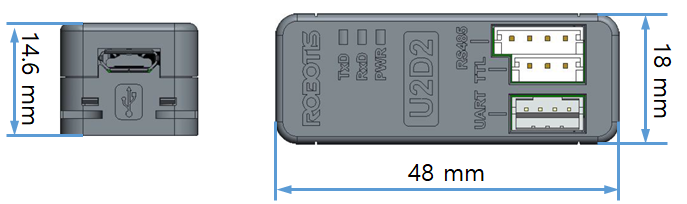
| Dimensions | 48mm x 18mm x 14.6mm |
| Ports | 3Pin TTL Level(TTL Communication supported DYNAMIXEL) 4Pin RS-485(RS-485 Communication supported DYNAMIXEL) 4Pin UART(Controllers that support 4Pin UART(such as CM-150 and CM-200) |
| Baudrate | Maximum 6Mbps |
![]()
DANGER
(May cause serious injury or death)
- Never place items containing water, flammables, or solvents near the product.
- Never place fingers, arms, toes, and other body parts near product during operation.
- Cut the power off if the product begins to emit strange odors or smoke.
- Keep product out of reach of children.
- Check input polarity before installing wiring or cables.
![]()
CAUTION
(May cause injury or damage to product)
- Always comply with operating environment specifications including voltage, current, and temperature.
- Do not insert blades or other sharp objects during product operation.
![]()
ATTENTION
(May cause injury or damage to product)
- Do not disassemble or modify the product.
- Do not drop or apply strong impacts to the product.
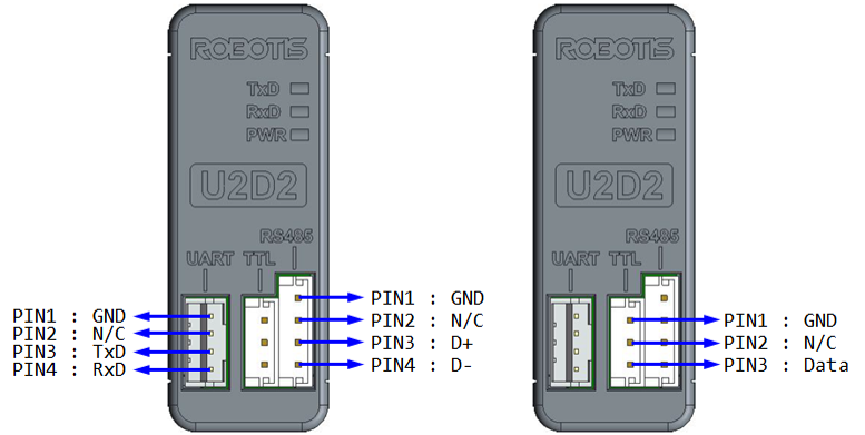
Layout
| Ports | Description |
|---|---|
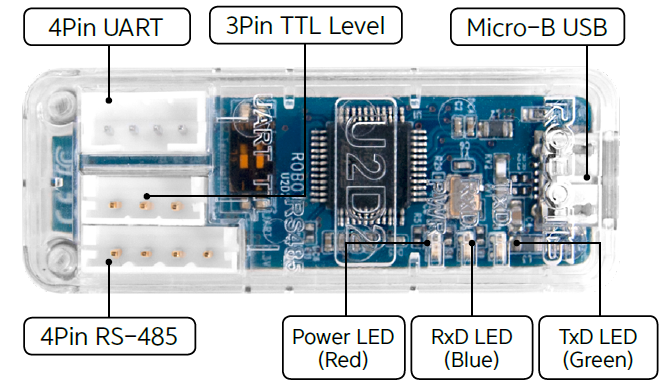
| 4Pin UART | Convert USB and UART |
| 3Pin TTL Level | Connect to DYNAMIXEL with 3Pin TTL Level Communication |
| 4Pin RS-485 | Connect to DYNAMIXEL with 4Pin RS-485 Communication |
| Status LED | Display status of Power supply, TxD(Data write) and RxD(Data Read) |
| Micro-B USB | Connect to the PC with USB cable |
Baudrate
| Reference BPS | Actual BPS | Error(%) |
|---|---|---|
| 9,600 | 9,600 | 0.00 |
| 57,600 | 57,588.4823 | -0.02 |
| 115,200 | 115,246.0984 | 0.04 |
| 1,000,000 | 1,000,000 | 0.00 |
| 2,000,000 | 2,000,000 | 0.00 |
| 3,000,000 | 3,000,000 | 0.00 |
| 4,000,000 | 4,000,000 | 0.00 |
| 4,500,000 | 4,571,428.571 | 1.56 |
| 6,000,000 | 6,000,000 | 0.00 |
NOTE : Less than 3% of the baud rate error will not affect to the UART communication.
NOTE : For the stable communication with higher baudrate, configure USB Latency value to the lower.
USB Latency Setting
Supply Power
U2D2 does not supply power to DYNAMIXEL, therefore, an external power supply should provide power to DYNAMIXEL as below. Before connecting DYNAMIXEL to an external power supply, please check the recommended voltage for DYNAMIXEL.
Caution for Power Supply
- For a stable power supply, it is recommended to use ROBOTIS controller or SMPS2Dynamixel.
- When connecting cable to DYNAMIXEL, please turn off the power.
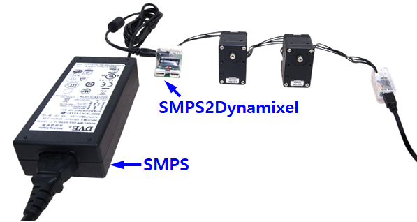
Using SMPS2Dynamixel
In order to operate DYNAMIXEL with SMPS2Dynamixel, please connect DYNAMIXEL to SMPS2Dynamixel, then connect SMPS to SMPS2Dynamixel as shown below image.
Please compare operating voltage of DYNAMIXEL with 12V 5A ROBOTIS SMPS before supplying power.
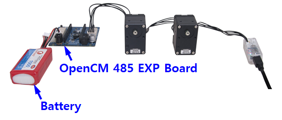
Using ROBOTIS Controller
In order to operate DYNAMIXEL with OpenCM 485 Expansion board, please connect DYNAMIXEL to OpenCM485 Exp board, then connect battery or SMPS to the expansion board as shown below image.
Please compare operating voltage of DYNAMIXEL with battery or 12V 5A ROBOTIS SMPS before supplying power.
OpenCM485 EXP board will bypass the input power source to output power.
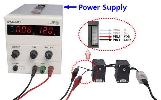
Using Power Supply
In order to operate DYNAMIXEL with Power Supply, please configure the power supply for DYNAMIXEL before connecting cable.
Please check the pinout of the cable to avoid connecting to wrong pins.
How to check whether the USB downloader(LN-101) driver is installed correctly.
Pinouts
Data Flow Control
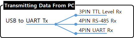
When data is transmitted from the USB port in PC to peripheral devices(Tx), all connected device will receive an identical data.
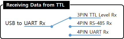
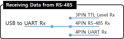
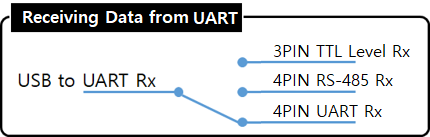
On the other hand, when data is received from one of the peripheral devices(Rx), it will be automatically converted as USB communication and sent to the PC. During this process, received data will not be transmitted to other peripheral devices. If data from more than two peripheral devices are received, the received data can be corrupted.
Therefore, when connecting 3Pin TTL Level DYNAMIXEL and 4Pin RS-485 DYNAMIXEL at the same time, all connected DYNAMIXEL should have its unique ID in order to prevent receiving corrupt data. In addition, when using Bulk Read and Sync Read instructions that requires to receive data from multiple DYNAMIXEL’s, relevant DYNAMIXEL’s should be connected to the same communication channel or else the instruction will not work properly.
Software
- RoboPlus
RoboPlus supports Windows environment to manage controllers and DYNAMIXEL’s.
- R+ Task 2.0 : R+ Task 2.0 can be used when downloading Task Code to the controller.
- R+ Motion 2.0 : R+ Motion 2.0 can be used when downloading Motion file to the controller.
- R+ Manager 2.0 : R+ Manager 2.0 is used to connect controllers or DYNAMIXEL’s and update firmware or test the control table..
- R+ Task 3.0 : Integrated software with R+ Task 2.0 and R+ Motion 2.0
- DYNAMIXEL Workbench
DYNAMIXEL Workbench supports Linux environment to test control table of DYNAMIXEL.
- DYNAMIXEL SDK
DYNAMIXEL SDK supports various programming languages such as C, C++, C#, MATLAB, LabVIEW, Python and Java in order to help developing DYNAMIXEL control software. DYNAMIXEL SDK provides a bundle of functions/methods that can be used for operating DYNAMIXEL with protocols in the form of digital packet. DYNAMIXEL SDK is free to download from GitHub.
Additional Features
Internal DIP Switch
There is a two-pole switch inside of the plastic cover. This switch is set to OFF as a default. Under normal circumstances this default setting is recommended, therefore, the switch cannot be accessed without opening the case. Please open the case and set RS-485 termination resistor and UART 3.3V power switch only after thoroughly understand its usage.
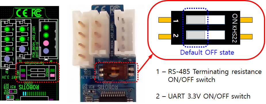
RS-485 Termination Resistor(120Ω) Switch
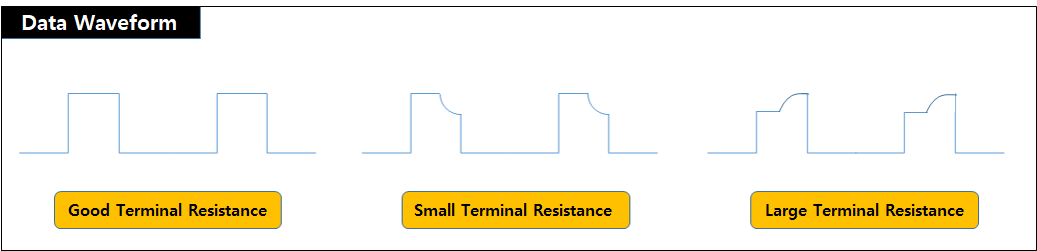
Transmission devices are designed to have certain impedances based on design standard and signal reflection or interference can occur when impedance do not match over the transmission lines. The termination resistors at the end of transmission lines suppress such effect by adjusting impedance and allowing constant current flow. However, the termination resistor is not a mandatory, especially in a short RS-485 network with lower communication baud rate.
If communication is suffering from frequent errors, the termination resistor might be required. The regular 120Ω termination resistor will be applied on the transmission line by shifting the switch to ON. If termination resistor doesn’t resolve the communication issue, the resistance value might need to be adjusted.
UART 3.3V Power Supply Switch
The peripheral device such as controllers that can be connected to the 4Pin UART usually have an external power source, therefore additional 3.3V power from the UART port #2 pin is not necessary.
However, when connecting BT-410 that does not have an external power source needs to be powered by the 4Pin UART port #2 pin. In this case, the UART 3.3V power switch need to be turned on.
If the switch is turned on, second pin of the 4Pin UART connector will be able to supply 3.3V.
Caution for Assembly
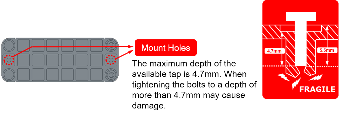
- Bolt for Mount Hole : M2 Tap bolt
- Mount Hole Depth : Valid depth 4.7mm, Depth from the surface 5.5mm
References
Connector Information
| Item | TTL | RS-485 |
|---|---|---|
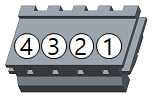
| Pinout | 1 GND2 VDD3 DATA |
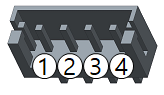
1 GND2 VDD3 DATA+4 DATA- |
| Diagram |  |
 |
| Housing | 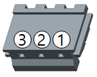 JST EHR-03 |
 JST EHR-04 |
| PCB Header | 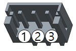 JST B3B-EH-A |
 JST B4B-EH-A |
| Crimp Terminal | JST SEH-001T-P0.6 | JST SEH-001T-P0.6 |
| Wire Gauge for DYNAMIXEL | 21 AWG | 21 AWG |
USB Latency Setting
For the most reliable high-speed communication with DYNAMIXEL it is recommended to reduce USB port latency as described below.
Windows
-
Open
Device Manager. Go toPortsitem and right click on the relative serial port to selectProperties.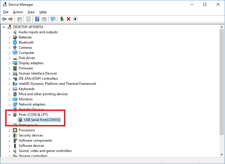
-
In the Properties window, go to
Port Settingstab and clickAdvancedbutton.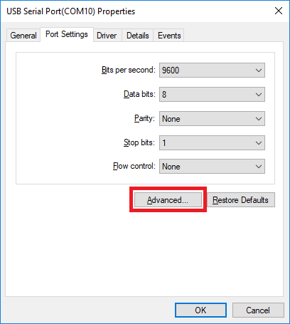
-
Set the
Latency Timer (msec)to1msand clickOKto confirm the change.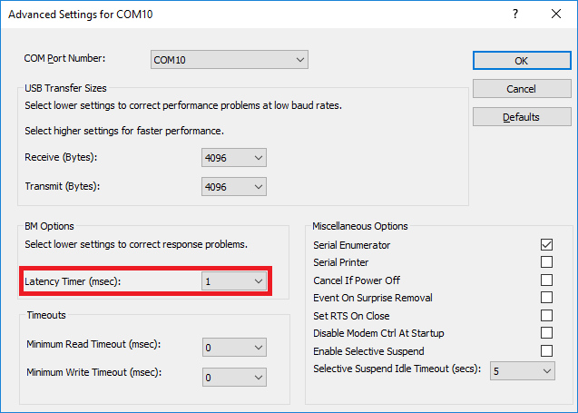
Linux
-
Execute below commands to configure the
latency_timerto1ms.# cat /sys/bus/usb-serial/devices/ttyUSB0/latency_timer 16 # echo 1 > /sys/bus/usb-serial/devices/ttyUSB0/latency_timer # cat /sys/bus/usb-serial/devices/ttyUSB0/latency_timer 1
Certifications
Please inquire us for information regarding unlisted certifications.
FCC
Note: This equipment has been tested and found to comply with the limits for a Class A digital device, pursuant to part 15 of the FCC Rules. These limits are designed to provide reasonable protection against harmful interference when the equipment is operated in a commercial environment. This equipment generates, uses, and can radiate radio frequency energy and, if not installed and used in accordance with the instruction manual, may cause harmful interference to radio communications. Operation of this equipment in a residential area is likely to cause harmful interference in which case the user will be required to correct the interference at his own expense.
WARNING
Any changes or modifications not expressly approved by the manufacturer could void the user’s authority to operate
the equipment.