
References
Brochure
Download PDFOutside pages (1, 4)Download PDFInside pages (2, 3)
Specifications
- Main controller : powered by Intel Atom Z530 CPU (clocked @ 1.6GHz)
- Sub controller : powered by STMicroelectronics Cortex-M3 STM32F103RE (clocked at 73MHz).
- Camera
- 2MP HD webcam with up to 1600x1200 resolution (720p-capable)
- 30 fps
- YUV (capture format)
- Carl Zeiss focus.
LinkOverall SpecificationsDownload PDFDiagrams
Hardware Specifications
Core Component Specifications
- Main Controller (fit-PC2i)
| Feature | Specifications |
|---|---|
| CPU | Intel Atom Processor: Z530 - 1.6Ghz @533MHz FSB L2-512KB(dynamic sizing), L1-32KB IC, 24KB DC. Intel Deep Power Down(C6) technology support |
| Chipset | Poulsbo US15 Intel System Controller Hub (INTEL SCH) |
| Memory | 1GB DDR2, 533MHz, 64-bit |
| Solid State Disk | 3.6GB NAND flash disk |
| Display Interface | SDVO based DVI interface(up to 1920x1080). Hotplug support. |
| Audio | Realtek ALC260, High Definition Audio, Line Out, shared line-in / mic-in |
| Ethernet | based on Gigabit PCI-Express controller Realtek RTL8111 |
| WiFi | 802.11 b/g/n capabilities, using RaLink RT3070 USB module. Up to 150Mbps, 2.4GHz band. |
| USB | 2 external USB ports |
| BIOS | Phoenix SecureCore BIOS |
| SDIO slot | mini SD connector supporting SDIO1.1 and MMC4.1 |
| Active consumption | 5-7W depending on CPU load |
| Dimensions | 104 x 96 x 23 mm |
| MTBF | > 100,000 hours |
| Operation temperature | 0°C to 70°C |
| Storage temperature | -40°C to 85°C |
| Relative humidity | 10% to 90% (operation) 5% to 95% (storage) |
You may download CompuLab’s reference guide with detailed specifications here. You can also get information on the speaker, microphones, and camera.
- Sub Controller (CM-730)
- STMicroelectronics 32F103RE ARM Cortex 32-bit CPU (clocked @ 72MHz)
- Actuator Interface (TTL or RS-485 (5x) each)
- Converters (USB-to-Serial, ADC)
- Actuator (DYNAMIXEL MX-28)
- Stall torque 24kgf.cm @ 12V
- Maxon RE-Max customized DC motor
- 193:1 reduction ratio
- Up to 3Mbps buffered TTL interface
- User programmable PID Gain
- Up to 4096 resolution absolute encoder
- DYNAMIXEL Protocol 1.0
- Interface
- 3 buttons
- 7 LED’s (2EA : 15-bit RGB, user-programmable)
- Sensors
- IMUs (3-axis accelerometers, 3-axis gyroscope, both intrgrated into sub controller)
- Image (2MP Logitech C905) HD Camera
- (OPTION) Force: 4 FSR per foot
- Battery (LiPo)
- Voltage : 11.1V
- Capacity : 1000 mAh
- Discharge : 10C
- Dimension : 70 x 35 x 15
- Weight : 83g
- PCM embedded to protect from over charge, over discharge, and excess current.
- PCB Schematics
Download PDFHead PCB SchematicDownload PDFInterface(Back Panel) PCB SchematicDownload PDFPower Schematic
Sub Controller
Download ZIPFrameworkDownload PDFSchematicsDownload ZIPReference Guide
You can also get information about the gyroscope and accelerometer.
How to convert TTL to RS485
Simply apply the 2 changes below to change the comm. method.
- Yellow Rectangle : Change location of resistance
- RS24 Short : 3P
- R25 Short : 4P
- Red Rectangle : Must change connector.
- Not sold separately by ROBOTIS.
For more information on the connector, please refer to the MX-28 Connector Information.
Features
| Feature | Specifications |
|---|---|
| CPU | STMicroelectronics 32F103RE ARM Cortex 32-bit CPU (clocked @ 72MHz) (512KB Flash, 64KB SRAM ) |
| Interface | 5 x LED , 2 x RGB LED, 3 x Button, 1 x Buzzer |
| External ports | 13 x ADC /I/O Ports |
| Sensor | 3-axis gyroscope , 3-axis accelerometer, supply voltage sensor |
| Communication | USB Port, Serial Port , 5x TTL Ports (for DYNAMIXEL) |
| Audio & Mic Amp | Audio amp gain : 20, mic amp gain : 2027 |
| ETC | DYNAMIXEL Power Control Unit, Head board port, Interface board port. |
| External supply voltage | 8V ~ 16.8v |
| Current consumption | Maximum 150mA , Standby 50mA |
| Dimensions | 80.0mm x 75.0mm x 20.0mm |
| Operation temperature | -65°C to +80°C |
| Weight | 51g |
Control Table
Control Table consists of data regarding the current status and operation of CM-730. The user can control CM-730 by changing data of Control Table via Instruction packet.
EEPROM and RAM
Data in RAM area is reset to initial values whenever the power is turned on while data in EEPROM area is kept once values are set even if the power is turned off.
Address
Represents the location of data. To read from or write data to the control table the user should assign the correct address in the Instruction packet.
Access
CM-730 has two kinds of data: Read-only data, used mainly for sensing, and read-and-write data used for driving.
Initial Value
In case of data in the EEPROM Area, the initial values on the right side of the below Control Table are the factory default settings.
In case of data in the RAM Area, the initial values on the right side of the following control table are the ones when the power is turned on.
Highest/Lowest Byte
In the Control table, some data share the same name, but they are attached with (L) or (H) at the end of each name to distinguish the address. This data requires 16-bit, but it is divided into 8bit each for the addresses (low) and (high). These two addresses should be written with one Instruction Packet simutaneously.
EEPROM Area
| Address | Name | Description | Access | Init Value |
|---|---|---|---|---|
| 0 (0X00) | Model Number(L) | model number low byte | R | 0(0X00) |
| 1 (0X01) | Model Number(H) | model number high byte | R | 115 (0X73) |
| 2 (0X02) | Version of Firmware | firmware version | R | - |
| 3 (0X03) | ID | DYNAMIXEL ID | RW | 200 (0XC8) |
| 4 (0X04) | Baud Rate | DYNAMIXEL baud rate | RW | 1 (0X01) |
| 5 (0X05) | Return Delay Time | Return Delay Time | RW | 0 (0X0) |
| 16 (0X10) | Status Return Level | Status Return Level | RW | 2 (0X02) |
RAM Area
| Address | Name | Description | Access | Init Value |
|---|---|---|---|---|
| 24 (0X18) | DYNAMIXEL Power | DYNAMIXEL On/Off | RW | 0 (0X00) |
| 25 (0X19) | LED Pannel | LED Pannel On/Off | RW | 0 (0X00) |
| 26 (0X1A) | LED 5 (L) | LED 5 low byte | RW | 0 (0X00) |
| 27 (0X1B) | LED 5 (H) | LED 5 high byte | RW | 0 (0X01) |
| 28 (0X1C) | LED 6 (L) | LED 6 low byte | RW | 0 (0X00) |
| 29 (0X1D) | LED 6 (H) | LED 6 high byte | RW | 0 (0X01) |
| 30 (0X1E) | Button | Button status | R | - |
| 38 (0X26) | Gyro_Z(L) | Gyroscope Z-axis low byte | R | - |
| 39 (0X27) | Gyro_Z(H) | Gyroscope Z-axis high byte | R | - |
| 40 (0X28) | Gyro_Y(L) | Gyroscope Y-axis low byte | R | - |
| 41 (0X29) | Gyro_Y(H) | Gyroscope Y-axis high byte | R | - |
| 42 (0X2A) | Gyro_X(L) | Gyroscope X-axis low byte | R | - |
| 43 (0X2B) | Gyro_X(H) | Gyroscope X-axis high byte | R | - |
| 44 (0X2C) | ACC_X(L) | Accelerometer X-axis low byte | R | - |
| 45 (0X2D) | ACC_X(H) | Accelerometer X-axis high byte | R | - |
| 46 (0X2E) | ACC_Y(L) | Accelerometer Y-axis low byte | R | - |
| 47 (0X2F) | ACC_Y(H) | Accelerometer Y-axis high byte | R | - |
| 48 (0X30) | ACC_Z(L) | Accelerometer Z-axis low byte | R | - |
| 49 (0x31) | ACC_Z(H) | Accelerometer Z-axis high byte | R | - |
| 50 (0X32) | Present Voltage | Current Voltage | R | - |
| 51 (0X33) | MIC 1 (L) | Mic 1 low byte | R | - |
| 52(0x34) | MIC 1 (H) | Mic 1 high byte | R | - |
| 53(0x35) | ADC 2(L) | ADC channel 2 low byte | R | - |
| 54(0x36) | ADC 2(H) | ADC channel 2 high byte | R | - |
| 55(0x37) | ADC 3(L) | ADC channel 3 low byte | R | - |
| 56(0x38) | ADC 3(H) | ADC channel 3 high vyte | R | - |
| 57(0x39) | ADC 4(L) | ADC channel 4 low byte | R | - |
| 58(0x3A) | ADC 4(H) | ADC channel 4 high byte | R | - |
| 59(0x3B) | ADC 5(L) | ADC channel 5 low byte | R | - |
| 60(0x3C) | ADC 5(H) | ADC channel 5 high byte | R | - |
| 61(0x3D) | ADC 6(L) | ADC channel 6 low byte | R | - |
| 62(0x3E) | ADC 6(H) | ADC channel 6 high byte | R | - |
| 63(0x3F) | ADC 7(L) | ADC channel 7 low byte | R | - |
| 64(0x40) | ADC 7(H) | ADC channel 7 high byte | R | - |
| 65(0x41) | ADC 8(L) | ADC channel 8 low byte | R | - |
| 66(0x42) | ADC 8(H) | ADC channel 8 high byte | R | - |
| 67(0x43) | MIC 2 (L) | Mic 2 low byte | R | - |
| 68(0x44) | MIC 2 (H) | Mic 2 high byte | R | - |
| 69(0x45) | ADC 10(L) | ADC channel 10 low byte | R | - |
| 70(0x46) | ADC 10(H) | ADC channel 10 high byte | R | - |
| 71(0x47) | ADC 11(L) | ADC channel 11 low byte | R | - |
| 72(0x48) | ADC 11(H) | ADC channel 11 high byte | R | - |
| 73(0x49) | ADC 12(L) | ADC channel 12 low byte | R | - |
| 74(0x4A) | ADC 12(H) | ADC channel 12 high byte | R | - |
| 75(0x4B) | ADC 13(L) | ADC channel 13 low byte | R | - |
| 76(0x4C) | ADC 13(H) | ADC channel 13 high byte | R | - |
| 77(0x4D) | ADC 14(L) | ADC channel 14 low byte | R | - |
| 78(0x4E) | ADC 14(H) | ADC channel 14 high byte | R | - |
| 79(0x4F) | ADC 15(L) | ADC channel 15 low byte | R | - |
| 80(0x50) | ADC 15(H) | ADC channel 15 high byte | R | - |
Address Function Help
Model Number
Represents the Model Number.
Firmware Version
Represents the firmware version.
ID
Is a unique number to identify DYNAMIXEL.
Values range from 0 (0x00) to 253 (0xFD), Value 254 (0xFE) is used as the Broadcast ID.
If the Broadcast ID is used to transmit Instruction Packet, then it can command to all DYNAMIXEL.
NOTE : Please be careful not to duplicate the ID of connected DYNAMIXEL.
Baud Rate
Represents the communication speed. 0 (0x00) to 254 (0xFE) can be used for it. This speed is calculated by using the below formula.
Speed(BPS) = 2000000/(Data+1)
| Data | Set BPS | Target BPS | Tolerance |
|---|---|---|---|
| 1 | 1000000.0 | 1000000.0 | 0.000 % |
| 3 | 500000.0 | 500000.0 | 0.000 % |
| 4 | 400000.0 | 400000.0 | 0.000 % |
| 7 | 250000.0 | 250000.0 | 0.000 % |
| 9 | 200000.0 | 200000.0 | 0.000 % |
| 16 | 117647.1 | 115200.0 | -2.124 % |
| 34 | 57142.9 | 57600.0 | 0.794 % |
| 103 | 19230.8 | 19200.0 | -0.160 % |
| 207 | 9615.4 | 9600.0 | -0.160 % |
NOTE : Maximum Baud Rate error of 3% is within the tolerance of UART communication.
Return Delay Time
Is the delay time per data value that takes from the transmission of Instruction packet until the return of Status packet.
0 (0x00) to 254 (0xFE) can be used. The delay time per data value is 2 microseconds (usec).
If the data value is delayed by 10, 20 usec the initial value is 250 (0xFA) (i.e., 0.5 msec).
Status Return Level
Decides how to return Status packet. There are three possibilities:
| Value | Return of Status Packet |
|---|---|
| 0 | No return against all commands (Except PING Command) |
| 1 | Return only for the READ command |
| 2 | Return for all commands |
NOTE : When Instruction packet is Broadcast ID, Status packet is not returned regardless of Status return level.
DYNAMIXEL Power
| Value | Meaning |
|---|---|
| 0 | Turn off the power of all DYNAMIXEL connected to CM-730. |
| 1 | Turn on the power of all DYNAMIXEL connected to CM-730. |
LED Pannel
| BIT | 7 ~ 3 | 2 | 1 | 0 |
|---|---|---|---|---|
| Value | X | LED4 | LED3 | LED2 |
If each bit is SET, applicable LED lights up.
If each bit is RESET, applicable LED goes off.
EX) When the LED Panel = 3 (00000101), the LED4 and LED2 light up.
LED5 / LED6
| BIT | 15 | 14 ~ 10 | 9 ~ 5 | 4 ~ 0 |
|---|---|---|---|---|
| Value | X | the value of blue light | the value of green light | the value of red light |
LED HEAD/ LED EYE is 3 color LED. It can represent the value of 32 steps by colors.
It can be represent by controling the value of light by colors.
BUTTON STATUS
| BIT | 7 ~ 2 | 1 | 0 |
|---|---|---|---|
| Value | X | the state value of START button | the state value of MODE button |
It is the value which represents the state of buttons.
If the bit is SET, it represents that the button is pressed.
If the bit is RESET, it represents that the button isn’t pressed.
GYRO / ACC
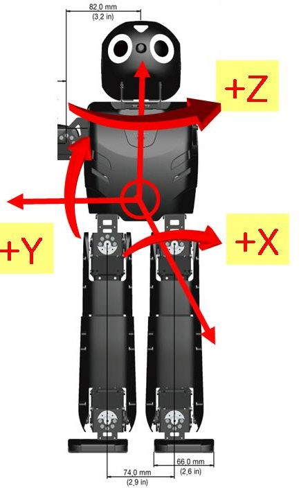
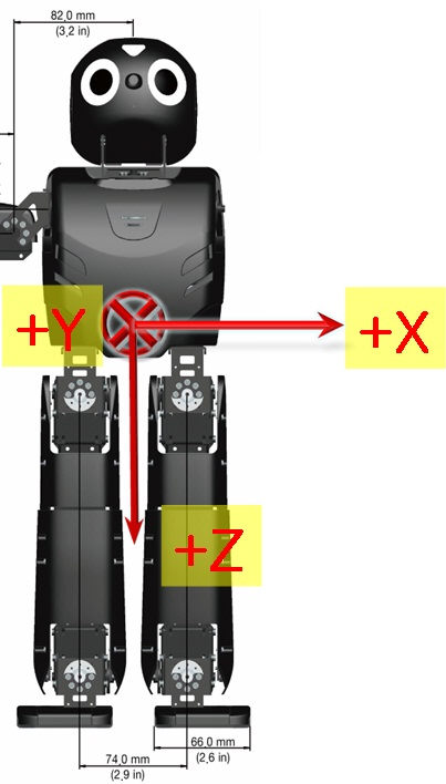
The following picture is the direction of axis at CM-730.
The Gyroscope and Accelerometer is 10mm distant respectively from the central axis of Dawin.
The positions of central axis and sensor at Dawin
Gyroscope
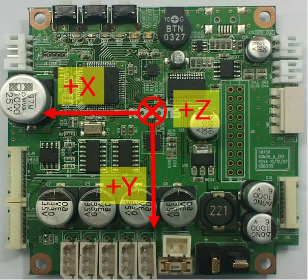
Accelerometer
 |
 |
|---|---|
| The Gyroscope axis in the DARWIN-OP | The Accelerometer axis in DARWIN-OP |
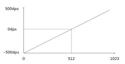
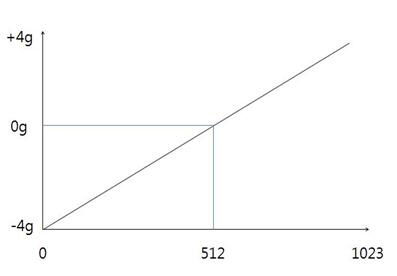
GYRO_X, GYRO_Y, GYRO_Z
They represent the angular velocity values of X-axis, Y-axis, Z-axis respectively.
The observable maximum velocity is -500DPS ~ 500DPS.
The following graph shows the process that angular velocity represents to value in reality.
ACC_X, ACC_Y, ACC_Z
They represent the acceleration values of X-axis, Y-axis, Z-axis respectively.
The observable maximum velocity is -4g ~ +4g.
The following graph shows the process that acceleration represents to value in reality.
PRESENT VOLTAGE
Present (input) voltage.
This value is 10 times larger than the actual voltage. For example, when 10V is supplied, the data value is 100 (0x64)
MIC 1 , MIC 2
They are the wave values of MIC on the ears at HEAD PCB.
It is the value of ADC, and its range is 0~1023.
ADC 2 ~ ADC15
They are ADC values of ADC channel connected external port(J8).
CM-730 has ADC of 10BIT RESOLUTION.
Its range is 0~1023
FSR(Force Sensing Resister)
| Feature | Specifications |
|---|---|
| Voltage | 9V~12V |
| Running Temperature | -5°C ~ +80°C |
| Command Signal | Digital Packet |
| Protocol Type | Half duplex Asynchronous Serial Communication (8bit,1stop,No Parity) |
| Link (Physical) | TTL Level Multi Drop (daisy chain type Connector) |
| ID | 254 ID (0~253) |
| Communication Speed | 7,843bps ~ 3 Mbps |
| Feedback | Position, Temperature, Load, Input Voltage, etc. |
| Standby current | 50 mA |
Control Table
Control Table consists of data regarding the current status and operation of DYNAMIXEL. The user can control DYNAMIXEL by changing data of Control Table via Instruction packet.
EEPROM and RAM
Data in RAM area is reset to initial values whenever the power is turned on while data in EEPROM area is kept once values are set even if the power is turned off.
Address
Represents the location of data. To read from or write data to the control table the user should assign the correct address in the Instruction packet.
Access
DYNAMIXEL has two kinds of data: Read-only data, used mainly for sensing, and read-and-write data used for driving.
Initial Value
In case of data in the EEPROM Area, the initial values on the right side of the below Control Table are the factory default settings.
In case of data in the RAM Area, the initial values on the right side of the following control table are the ones when the power is turned on.
Highest/Lowest Byte
In the Control table, some data share the same name, but they are attached with (L) or (H) at the end of each name to distinguish the address. This data requires 16-bit, but it is divided into 8bit each for the addresses (low) and (high). These two addresses should be written with one Instruction Packet simutaneously.
EEPROM Area
| Address | Name | Description | Access | Init Value |
|---|---|---|---|---|
| 0 (0X00) | Model Number(L) | Lowest byte of model number | R | 84 (0X54) |
| 1 (0X01) | Model Number(H) | Highest byte of model number | R | 1 (0X01) |
| 2 (0X02) | Version of Firmware | Information on the version of firmware | R | - |
| 3 (0X03) | ID | ID of DYNAMIXEL | RW | 100 (0X64) |
| 4 (0X04) | Baud Rate | Baud Rate of DYNAMIXEL | RW | 34 (0X22) |
| 5 (0X05) | Return Delay Time | Return Delay Time | RW | 250 (0XFA) |
| 16 (0X10) | Status Return Level | Status Return Level | RW | 2 (0X02) |
RAM Area
| Address | Name | Description | Access | Init Value |
|---|---|---|---|---|
| 25 (0X19) | LED | LED On/Off | RW | 0 (0X00) |
| 26 (0X1A) | FSR1_L | Lowest byte of FSR 1 sensor data | R | - |
| 27 (0X1B) | FSR1_H | Highest byte of FSR 1 sensor data | R | - |
| 28 (0X1C) | FSR2_L | Lowest byte of FSR 2 sensor data | R | - |
| 29 (0X1D) | FSR2_H | Highest byte of FSR 2 sensor data | R | - |
| 30 (0X1E) | FSR3_L | Lowest byte of FSR 3 sensor data | R | - |
| 31 (0X1F) | FSR3_H | Highest byte of FSR 3 sensor data | R | - |
| 32 (0X20) | FSR4_L | Lowest byte of FSR 4 sensor data | R | - |
| 33 (0X21) | FSR4_H | Highest byte of FSR 4 sensor data | R | - |
| 34 (0X22) | FSR_Central_X | Center point of the X-axis force | R | - |
| 35 (0X23) | FSR_Central_Y | Center point of the Y-axis force | R | - |
| 42 (0X2A) | Present Voltage | Current Voltage | R | - |
| 44 (0X2C) | Registered | Means if Instruction is registered | R | 0 (0X00) |
| 47 (0X2F) | Lock | Locking EEPROM | RW | 0 (0X00) |
Address Function Help
Model Number
Represents the Model Number.
Firmware Version
Represents the firmware version.
ID
Is a unique number to identify DYNAMIXEL.
Values range from 0 (0x00) to 253 (0xFD), Value 254 (0xFE) is used as the Broadcast ID.
If the Broadcast ID is used to transmit Instruction Packet, then it can command to all DYNAMIXEL.
when it’s searched as Unknown Device, change the baudrate to 1(1000000).
Connect with DARWIN-OP after setting the ID as 111 for the right foot and 112 for the left.
NOTE : Please be careful not to duplicate the ID of connected DYNAMIXEL.
Baud Rate
Represents the communication speed. 0 (0x00) to 254 (0xFE) can be used for it. This speed is calculated by using the below formula.
Speed(BPS) = 2000000/(Data+1)
| Data | Set BPS | Target BPS | Tolerance |
|---|---|---|---|
| 1 | 1000000.0 | 1000000.0 | 0.000 % |
| 3 | 500000.0 | 500000.0 | 0.000 % |
| 4 | 400000.0 | 400000.0 | 0.000 % |
| 7 | 250000.0 | 250000.0 | 0.000 % |
| 9 | 200000.0 | 200000.0 | 0.000 % |
| 16 | 117647.1 | 115200.0 | -2.124 % |
| 34 | 57142.9 | 57600.0 | 0.794 % |
| 103 | 19230.8 | 19200.0 | -0.160 % |
| 207 | 9615.4 | 9600.0 | -0.160 % |
NOTE : Maximum Baud Rate error of 3% is within the tolerance of UART communication.
Return Delay Time
Is the delay time per data value that takes from the transmission of Instruction packet until the return of Status packet.
0 (0x00) to 254 (0xFE) can be used. The delay time per data value is 2 microseconds (usec).
If the data value is delayed by 10, 20 usec the initial value is 250 (0xFA) (i.e., 0.5 msec).
Status Return Level
Decides how to return Status packet. There are three possibilities:
| Value | Return of Status Packet |
|---|---|
| 0 | No return against all commands (Except PING Command) |
| 1 | Return only for the READ command |
| 2 | Return for all commands |
NOTE : When Instruction packet is Broadcast ID, Status packet is not returned regardless of Status return level.
LED
| Value | Meaning |
|---|---|
| 0 | Turns LED off |
| 1 | Turns LED on |
 |
|---|
| Diagram 1 |
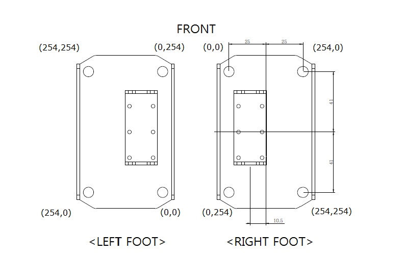
FSR1,FSR2,FSR3,FSR4
FSR sensor data. Diagram 1 shows the location of each sensor.
Value range is 0 ~ 65535. Each value has 1/1000 N units.
For example, FSR1 has a load of 9.8N(1kgf); the value of FSR1 is 9800.
The smallest measurement load is 0.493N.
The measurement range is 0.493 N ~ 65.535N.
FSR_Central_X, FSR_Central_Y
DARWIN-OP’s load is at the center of the foot.
Value range is 0 ~ 254.
When no load is present values will read 255.
Diagram 1 shows of the center point of each foot.
Present Voltage
Current input voltage. This value is 10 times larger than the actual voltage. For example, when 10V is supplied the data value is 100 (0x64).
Registered Instruction
| Value | Meaning |
|---|---|
| 0 | There are no commands transmitted by REG_WRITE |
| 1 | There are commands transmitted by REG_WRITE |
NOTE : If ACTION command is executed, the value is changed into 0.
Lock
| Value | Meaning |
|---|---|
| 0 | EEPROM area can be modified |
| 1 | EEPROM area cannot be modified |
CAUTION : If Lock is set to 1, the power must be turned off and then turned on again to change into 0.
Mechanical Specifications
Actuator ID Map
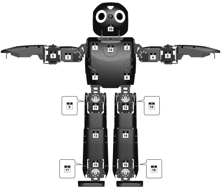
Download PDF ID Map
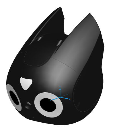
Camera (Logitech C905)
- Carl Zeiss® optics with autofocus
- Native 2MP HD sensor
- HD video capture (up to 1600x1200@10fps, 1280x720@30fps)
- 720p widescreen mode with recommended system
- Up to 8-megapixel photos (enhanced from native 2MP sensor)
- Microphone with Logitech® RightSound™ technology
- Hi-Speed USB 2.0 certified
- Output : MJPG, YUYV
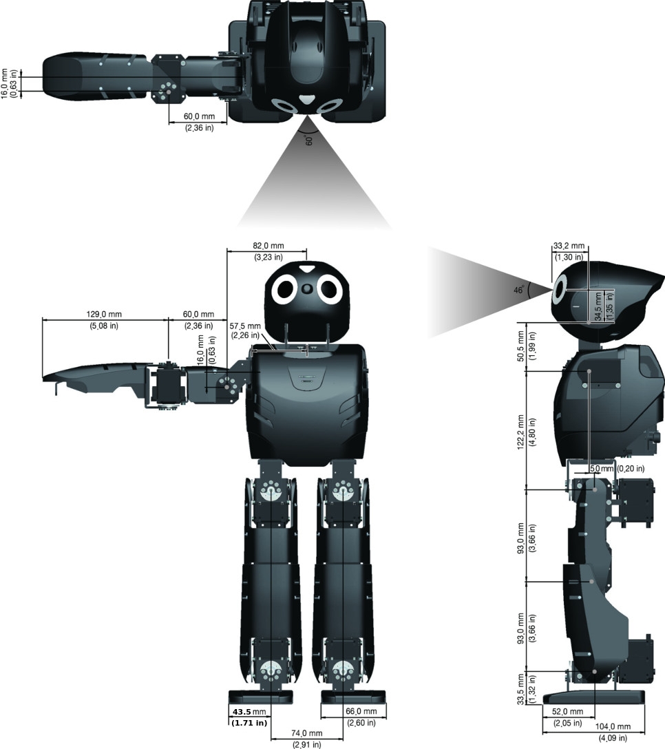
Dimensions
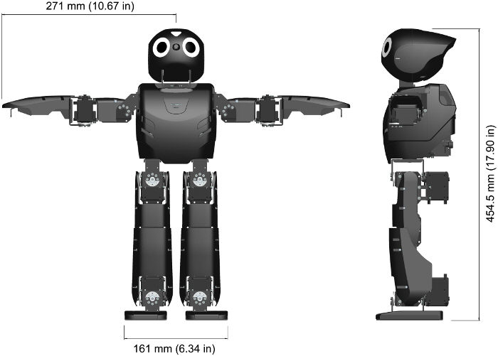
DARWIN-OP dimensions illustrated in both SI and Imperial units.
Weight: 2.9kg (6.39lb)
Total height: 454.5mm (17.90in)
Download PDFDimensionsDownload ZIP3D CAD FilesDownload PDFAssembly ManualDownload PDFWiring ManualDownload PDFFabrication Manual
Dynamics
Information regarding DARWIN-OP’s dynamics can be found here : DARWIN-OP_Dynamics.zip
Download ZIP3D CAD Files
Kinematics
Download ZIP DARWIN-OP Kinematics
Software Specifications
Main Controller
Recovery Software
Every DARWIN-OP robot comes equipped with a USB thumb drive loaded with factory-default setting recovery software.
Please visit the link periodically for updates
Download Recovery Software
Source Code
You can update the source code for DARWINOP via Subversion.
The source code also contains the color cards.
Download Source Code
Sub Controller(CM-730)
Download CM-730 Information
Software Update Info
Framework Release Note
Framework source code download : SourceForge DARWIN-OP framework
Ver 1.6.0 - 2013.04.11
- New Additions
- Webots controller can be compiled into DARwin-OP.
- DARWIN-OP can be controller from Webots GUI.
- MX28.cpp, Camera.cpp added to ensure compatibility with Webots.
- Modifications
- CM730, Image, Imgprocess, LinuxCamera, JointData, Action, Kinematics added Webots functionality
- MX28.h values now reside in MX28.cpp
- Camera.h values now reside in Camera.cpp
Ver 1.5.0 - 2012.03.19
- New Additions
- FSR firmware has been added.
- FSR tutorial has been adde
- Modifications
- LinuxMotionTimer has been changed to use clock_nanosleep function.
Ver 1.4.0 - 2012.01.16
- Modifications
- MX-28 firmware updated.
- Stand-up motion changed.
- Cannot change the camera gain/exposure value from a web page bug fixed.
- offset tuner ‘set’ command bug fixed.
Ver 1.3.0 - 2011.09.20
- New Additions
- offset_tuner added.
- web-based walk_tuner added.
- Modifications
- CM-730 firmware updated.
- roboplus support 4096 resolution(MX-28 firmware ver 27 or higher).
- dxl_monitor : can change baudrate (control table addr 4)
- Get-up motion changed.
- read_write tutorial : left arm P gain value changed. (1 -> 8)
Ver 1.2.0 - 2011.06.01
- New Additions
- BulkRead instruction added.
- Support for FSR sensor.
- Modifications
- Actuator Model name changed (RX-28M -> MX-28)
- MX-28 firmware updated.
- dxl_monitor : can change ID (control table addr 3)
- Get-up motion changed.
- Sensor calibration routine changed. (use standard deviation)
- demo & walk_tuner share the config.ini file. (/darwin/Data/config.ini)
- action_editor : command line bug fixed. (can’t input space or number)
linux terminal backspace bug fixed. - walk_tuner : linux terminal backspace bug fixed.
- read_write : at the start, torque off the right arm.
- firmware installer : seperate firmware of the controller and actuator
Ver 1.1.0 - 2011.04.08
- New Additions
- firmware_installer : CM-730 & RX-28M firmware installer
- Modifications
- CM-730 firmware updated. (ver 0x11)
- RX-28M firmware updated (ver 0x1B)
- Action class : type casting bug fixed.
- dxl_monitor : CM-730 control table dump bug fixed.
- action_editor : command line first char backspace bug fixed. / save command bug fixed.
- walk_tuner : command line first char backspace bug fixed.
- some minor bug fixed.
Ver 1.0.1 - 2011.03.28
- Modifications
- LinuxCM730 class : move semaphore initial code to constructor
- action_script : stand-up motion page number changed from 16 to 1
- demo : at the start of soccer mode, reset the gyro sensor calibration
- Some walking parameters changed.
- action_editor : page 255 access problem fixed.
- Walking class : Y move amplitude bug fixed.
Ver 1.0.0 - 2011.02.01
- First Release
CM-730 Firmware Release Note
CM-730 Firmware source code download : SourceForge CM730 Firmware
Ver 19 (0x13) - 2011.08.26
- New Additions
- Reset Instruction added.
- Modifications
- Baudrate bug fixed.
- Increase TX/RX LED turn on time.
- Mic. Control table address changed. (67 -> 53)
- Battery alarm bug fixed.
- Read / Bulk Read Instruction process routine optimized.
Ver 18 (0x12) - 2011.04.26
- New Additions
- BulkRead instruction added.
- Modifications
- LED bug fixed.
Ver 17 (0x11) - 2011.04.08
- New Additions
- Low battery alarm added.
- Modifications
- USB recognition method changed (interrupt -> polling)
Ver 16 (0x10) - 2011.02.28
- First Release
MX-28 Firmware Release Note
DYNAMIXEL firmware is NOT an open source software.
Ver 30 (0x1E) - 2012.01.05
- New Additions
- The new hardware was applied.
- added self-calibration algorithms.
- added calibration data protection algorithms.
- Modifications
- CPU main clock was updated to 72MHz.
- fixed EEPROM bug.
Ver 29 (0x1D) - 2011.05.18
- Modifications
- Wheel mode bug fixed.
Ver 28 (0x1C) - 2011.05.02
- Modifications
- PID Resolution 4 times increase.
- P gain default value changed. (8 -> 32)
Ver 27 (0x1B) - 2011.04.11
- New Additions
- PID Control
- Modifications
- Resolution changed from 1024 to 4096.
Ver 26 (0x1A) - 2011.02.28
- First Release
FSR Firmware Release Note
FSR firmware is NOT an open source software.
Ver 17 (0x11) - 2012.03.08
- First Release
Links
Download DARWIN-OP Logo Images
Sites
- ROBOTIS(http://www.robotis.com)
- SourceForge(http://www.sourceforge.net/projects/darwinop)
- Collaborating Partners
- Robotics and Mechanics Laboratory, RoMeLa(http://www.romela.org/)
- University of Pennsylvania: GRASP Laboratories(http://www.grasp.upenn.edu/)
- Webots simulator for DARWIN-OP by Cyberbotics(http://www.cyberbotics.com/overview)
Recommended Tools
- PC
- Remote Desktop: Real VNC(http://www.realvnc.com/)
- SSH Slient: PuTTY(http://www.putty.org/), ZOC(http://www.emtec.com/zoc)
- MAC
- Remote Desktop: Chicken of the VNC(http://www.macupdate.com/app/mac/9517/chicken-of-the-vnc)
- SSH client: RBrowser(http://www.rbrowser.com/)
- iOS
- There are many remote desktop and SSh client apps for iOS devices. The listed ones below are free of charge.
- Remote Desktop: Mocha VNC Lite(http://itunes.apple.com/us/app/mocha-vnc-lite/id284984448?mt=8)
- SSH client: SSH Mobile Free(http://itunes.apple.com/us/app/ssh-mobile-free/id481718124?mt=8)
- Android
- There are several free of charge apps for the Android platform
- Remote Desktop: http://slodive.com/freebies/android-remote-desktop-apps/
- SSH client: http://www.androidzoom.com/android_applications/ssh+client+free
- Blackberry
- SSH client: BBSSH(http://www.bbssh.org/)
Text Editor Tutorials
- VI
- A convenient tool for screen-based editing. Extremely useful to write code. VI comes installed with DARWIN-OP, as well as, incorporated onto the restore USB thumbdrive.
- Tutorials: http://www.gentoo.org/doc/en/vi-guide.xml
- Emacs
- VI may seem very complicated to a lot of users. Emacs is an alternative to VI while being extremely useful as well for writing code. Emacs does not come pre-installed with DARWIN-OP but it can easily be installed and its memory footprint is negligible.
- Installation
- Ensure DARWIN-OP’c PC has internet access. On a command line type
- sudo apt-get install emacs
- Tutorials : http://www.gnu.org/s/emacs/tour/
- gedit
- GUI-based (either connected via remote desktop or directly via HDMI/DVI display).
- Just like VI; gedit is incorporated with DARWIN-OP. gedit is useful for users that want a GUI-based text editor and is just as useful for writing code.
- Tutorials: http://live.gnome.org/Gedit
Videos
DARWIN-OP Webots simulator
IEEE-RAS Humanoids Conference 2010 (Individual Presentations and Workshop)
Presentation by Dr. Dennis Hong.
Presentation by ROBOTIS’ CEO.
Presentation by JK Han.
Presentation by ROBOTIS’ VP.
Presentation by Dr. Daniel Lee.
UPenn workshop.
IEEE-RAS Humanoids Conference 2010 (Third Party clips)
Dr. Dennis Hong Interview while DARWIN-OP performs Interactive Mode at the conference.
- At IEEE RAS Humanoids DARWIN-OP:
InnoRobo 2011 Lyon, France
Recorded by a visitor
RoboCup 2011 (Istanbul, Turkey)
Team DARwin defeats the defending world champion (semifinal).
Team DARwin becomes world champion (final).
Popular Science
http://www.popsci.com/technology/article/2011-07/video-darwin-op-wants-tecate-not-bud-light
Other Third Party Clips
From Virginia Tech’s RoMeLa
Chasing and Kicking the ball
From a fan
DARWIN-OP in Japan
An independent opinion
Back on it feet
DAREIN-OP’s software
DARWIN-OP with gripper demo
Certifications
Please inquire us for information regarding unlisted certifications.
FCC
Note: This equipment has been tested and found to comply with the limits for a Class A digital device, pursuant to part 15 of the FCC Rules. These limits are designed to provide reasonable protection against harmful interference when the equipment is operated in a commercial environment. This equipment generates, uses, and can radiate radio frequency energy and, if not installed and used in accordance with the instruction manual, may cause harmful interference to radio communications. Operation of this equipment in a residential area is likely to cause harmful interference in which case the user will be required to correct the interference at his own expense.
WARNING
Any changes or modifications not expressly approved by the manufacturer could void the user’s authority to operate
the equipment.