
Tutorials
ROBOTIS-OP3 Bringup
Overview
This chapter explains how to operate the ROBOTIS-OP3. The op3_bringup demo launches op3_manager.
Several modules of op3_manager are used to control the ROBOTIS-OP3 and various topics and services transmit commands and report current status.
The op3_manager cooperates with other programs such as op3_demo and op3_gui_demo.
Reference : op3_manager
Test environment
- Linux Mint 22 Wilma (Base : Ubuntu Noble)
- ROS2 Jazzy
Getting started
Download & Build
Reference : Installing ROBOTIS ROS Package
Stop the Linux service that run default demo
ROBOTIS-OP3 runs the default demo automatically. To run the op3_bringup demo, you have to stop the default demo service.
$ sudo systemctl stop op3_demo.service
[sudo] password for robotis: 111111
Bringup
Type the commands below in a terminal window.
$ ros2 launch op3_bringup op3_bringup.launch.py
Note that, if the op3_bringup package is missing, update the package to download the missing package by following the given instruction.
$ cd ~/robotis_ws/src/ROBOTIS-OP3-Demo
$ git pull
$ cd ~/robotis_ws
$ colcon build --symlink-install
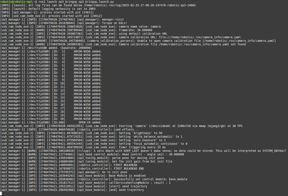
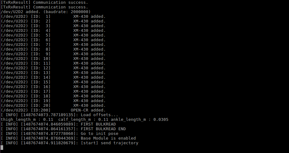
Execution result
When op3_bringup runs, the robot moves to it’s initial posture.
-
execution result screen
If you get an error for offset.yaml, run op3_offset_tuner(server and client) and save the offset.
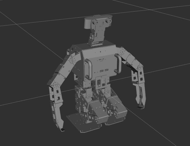
-
execution result on ROBOTIS-OP3 (Init pose in RVIZ)
-
It’s ready to move, now the user can control ROBOTIS-OP3 using a program such as op3_gui_demo.
-
If user turn off the program, press
ctrl+cin terminal window.
op3_bringup.launch.py
import launch
from launch import LaunchDescription
from launch_ros.actions import Node
from launch.actions import IncludeLaunchDescription
from launch.launch_description_sources import PythonLaunchDescriptionSource
from ament_index_python.packages import get_package_share_directory

def generate_launch_description():
  op3_manager_launch = IncludeLaunchDescription(
    PythonLaunchDescriptionSource(
      [get_package_share_directory('op3_manager'), '/launch/op3_manager.launch.py']
    )
  )

  usb_cam_node = Node(
    package='usb_cam',
    executable='usb_cam_node_exe',
    name='usb_cam_node_exe',
    output='log',
    parameters=[{
      'video_device': '/dev/video0',
      'image_width': 1280,
      'image_height': 720,
      'framerate': 30.0,
      'camera_frame_id': 'cam_link',
      'camera_name': 'camera',
      'io_method': 'mmap',
      'pixel_format': 'mjpeg2rgb',
      'av_device_format': 'YUV422P',
    }],
    remappings=[('/image_raw', '/usb_cam_node/image_raw')]
  )

  return LaunchDescription([
    op3_manager_launch,
    usb_cam_node
  ])
op3_manager: framework to control of ROBOTIS-OP3- Robot file :
op3_manager/config/OP3.robot - Joint initialize file :
op3_manager/config/dxl_init_OP3.yaml - Offset file :
op3_manager/config/offset.yaml
- Robot file :
usb_cam: package for usb camera of ROBOTIS-OP3
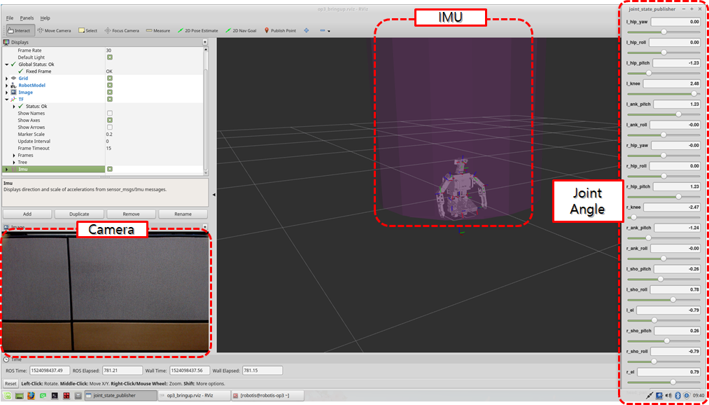
Visualization
Type the commands below in a terminal window for visualization.
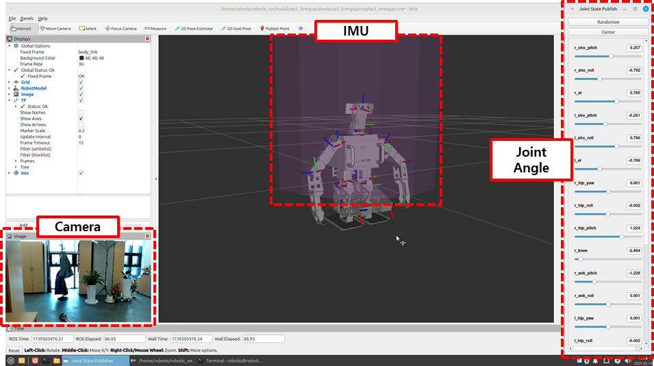
$ ros2 launch op3_bringup op3_bringup_visualization.launch.py
-
rviz2 screen
op3_bringup_visualization.launch.py
from launch import LaunchDescription
from launch.actions import DeclareLaunchArgument, IncludeLaunchDescription
from launch.substitutions import LaunchConfiguration, PathJoinSubstitution, Command
from launch_ros.substitutions import FindPackageShare
from launch_ros.actions import Node

from launch_ros.parameter_descriptions import ParameterValue

def generate_launch_description():
  ld = LaunchDescription()

  op3_description_path = FindPackageShare('op3_description')
  op3_urdf_path = PathJoinSubstitution([op3_description_path, 'urdf', 'robotis_op3.urdf.xacro'])
  op3_description_content = ParameterValue(Command(['xacro ', op3_urdf_path]), value_type=str)

  default_rviz_config_path = PathJoinSubstitution([op3_description_path, 'rviz', 'op3.rviz'])

  # Launch description
  # joint_state_publisher
#   ld.add_action(Node(
#     package='joint_state_publisher',
#     executable='joint_state_publisher',
#     parameters=[{'source_list': ['/robotis/present_joint_states']}],
#     remappings=[('/joint_states', '/robotis/present_joint_states')])
#   )

  # joint_state_publisher_gui
  ld.add_action(Node(
    package='joint_state_publisher_gui',
    executable='joint_state_publisher_gui',
    parameters=[{'source_list': ['/robotis/present_joint_states']}],
    remappings=[('/joint_states', '/robotis/present_joint_states')])
  )

  # robot_state_publisher
  ld.add_action(Node(
    package='robot_state_publisher',
    executable='robot_state_publisher',
    parameters=[{'robot_description': op3_description_content,}],
    remappings=[('/joint_states', '/robotis/present_joint_states'),],)
  )

  # Rviz
  ld.add_action(Node(
    package='rviz2',
    executable='rviz2',
    name='rviz2',
    output='screen',
    arguments=['-d', default_rviz_config_path],)
  )

  return ld
joint_state_publisher_gui: visualization of joint value of ROBOTIS-OP3robot_state_publisher: making TF message for robot modelrviz2: visualization tool
Description
This section explains configuration files used in the op3_manager (within op3_bringup.launch.py).
Robot file(.robot)
Information required for the robot to operate.
Control frequency, communication interface, baud rate, available devices and their properties are defined here.
-
Default path to Robot File :
op3_manager/config/OP3.robot -
Contents
[ control info ]
control_cycle = 8   # milliseconds

[ port info ]
# PORT NAME  | BAUDRATE  | DEFAULT JOINT
/dev/U2D2    | 2000000   | r_sho_pitch

[ device info ]
# TYPE    | PORT NAME    | ID  | MODEL          | PROTOCOL | DEV NAME       | BULK READ ITEMS
dynamixel | /dev/U2D2    | 1   | XM-430         | 2.0      | r_sho_pitch    | present_position
dynamixel | /dev/U2D2    | 2   | XM-430         | 2.0      | l_sho_pitch    | present_position
dynamixel | /dev/U2D2    | 3   | XM-430         | 2.0      | r_sho_roll     | present_position
dynamixel | /dev/U2D2    | 4   | XM-430         | 2.0      | l_sho_roll     | present_position
dynamixel | /dev/U2D2    | 5   | XM-430         | 2.0      | r_el           | present_position
dynamixel | /dev/U2D2    | 6   | XM-430         | 2.0      | l_el           | present_position
dynamixel | /dev/U2D2    | 7   | XM-430         | 2.0      | r_hip_yaw      | present_position
dynamixel | /dev/U2D2    | 8   | XM-430         | 2.0      | l_hip_yaw      | present_position
dynamixel | /dev/U2D2    | 9   | XM-430         | 2.0      | r_hip_roll     | present_position
dynamixel | /dev/U2D2    | 10  | XM-430         | 2.0      | l_hip_roll     | present_position
dynamixel | /dev/U2D2    | 11  | XM-430         | 2.0      | r_hip_pitch    | present_position
dynamixel | /dev/U2D2    | 12  | XM-430         | 2.0      | l_hip_pitch    | present_position
dynamixel | /dev/U2D2    | 13  | XM-430         | 2.0      | r_knee         | present_position
dynamixel | /dev/U2D2    | 14  | XM-430         | 2.0      | l_knee         | present_position
dynamixel | /dev/U2D2    | 15  | XM-430         | 2.0      | r_ank_pitch    | present_position
dynamixel | /dev/U2D2    | 16  | XM-430         | 2.0      | l_ank_pitch    | present_position
dynamixel | /dev/U2D2    | 17  | XM-430         | 2.0      | r_ank_roll     | present_position
dynamixel | /dev/U2D2    | 18  | XM-430         | 2.0      | l_ank_roll     | present_position
dynamixel | /dev/U2D2    | 19  | XM-430         | 2.0      | head_pan       | present_position
dynamixel | /dev/U2D2    | 20  | XM-430         | 2.0      | head_tilt      | present_position
sensor    | /dev/U2D2    | 200 | OPEN-CR        | 2.0      | open-cr        | button, present_voltage, gyro_x, gyro_y, gyro_z, acc_x, acc_y, acc_z, roll, pitch, yaw
Reference : Robot Information file(.robot)
Joint Initialize File (.yaml)
Set initialization values for properties of DYNAMIXEL or sensor.
-
Default path of Initialization file :
op3_manager/config/dxl_init_OP3.yaml -
Contents
r_sho_pitch :   # XM-430
   return_delay_time        : 1    # item name : value
   min_position_limit       : 0
   max_position_limit       : 4095

r_sho_pitch :   # XM-430
   return_delay_time        : 1    # item name : value
   min_position_limit       : 0
   max_position_limit       : 4095

...
Reference : Joint initialize file(.yaml)
Offset file(.yaml)
If the robot is mechanically distorted due to assembly tolerance or other reasons, adjusting offsets can help to correct the error.
The offset file contains offset angles for each joint, in radians, to correct distortion and initial posture joint angles for Offset Tuner.
-
Default path of Offset file :
op3_manager/config/offset.yaml -
Contents
offset:
  head_pan: 0
  head_tilt: 0
  l_ank_pitch: 0
  l_ank_roll: 0
  l_el: 0
  l_hip_pitch: 0
  l_hip_roll: 0
  l_hip_yaw: 0
  l_knee: 0
  l_sho_pitch: 0
  l_sho_roll: 0
  r_ank_pitch: 0
  r_ank_roll: 0
  r_el: 0
  r_hip_pitch: 0
  r_hip_roll: 0
  r_hip_yaw: 0
  r_knee: 0
  r_sho_pitch: 0
  r_sho_roll: 0
Reference : How to use offset tuner
How to execute Default Demo
Overview
This chapter explains how to use the basic demonstrations of the OP3. There are three available demos; playing soccer, vision and a sequence of various actions.
Reference : op3_demo
Getting started
Download & Build
Reference : Installing ROBOTIS ROS Package
Run
-
Auto Start
ROBOTIS-OP3 begins to play the demo on startup. -
Manual Start
Connect to the ROBOTIS-OP3 and open the terminal window.
The demo launch file executesop3_demoandop3_manager.$ ros2 launch op3_demo demo.launch.xml
Execution result
DYNAMIXELs in the ROBOTIS-OP3 will be powered and move to the initial posture.
Description
Button Functions
Starting from the left, the buttons are Mode, Start, User and Reset.
- Mode button
- short press : In Ready Mode, mode button switches to the next demo(soccer > vision > action)
- long press : While demo is running, press and hold the mode button to switch to Ready Mode.
- Start button
- short press : Play selected demo from Ready Mode. If demo is running, the start button will pause or resume the demo.
- User button
-
Reserved for user defined functions, not used by the default demos.
- Reset button
- The reset button will cut off the power to all connected DYNAMIXELs.
Soccer Demo
-
How to play
Press the mode button once from demonstration ready mode to switch to autonomous soccer mode, then start the soccer demo by pressing the start button.
(ROBOTIS-OP3 will announce “Autonomous soccer mode” and the red LED in the back will be lit.)
When the demo begins, ROBOTIS-OP3 will announce “Start soccer demonstration” and stand up to search for a ball.
If the desired ball is detected, it will walk close to the ball and kick it. - Setting Walking Parameters
Walking motion imports parameters saved in theop3_walking_moduleinop3_manager. Default parameters can be configured by using the walking tuner in theop3_gui_demo.Reference : How to use walking tuner
- Return to Demonstration Ready Mode
Pressing and holding the mode button for 3 seconds will make ROBOTIS-OP3 return to the initial posture and return to Demonstration ready mode.
Vision Demo
- How to Play
Press the mode button twice from demonstration ready mode to switch to vision processing mode, then play vision demo by pressing the start button. (ROBOTIS-OP3 will announce “Vision processing mode” and the green LED in the back will be lit.)
When the demo begins, ROBOTIS-OP3 will announce “Start vision processing demonstration” and stand up to search for a face.
If a face is detected, the RGB-LED on the chest and back will illuminate white and OP3’s head will follow the detected face.Reference : Face Tracker -
branch:jazzy-devel - Return to Demonstration Ready Mode
Pressing and holding the mode button for 3 seconds will make ROBOTIS-OP3 to return to the initial posture and return to Demonstration ready mode.
Action Demo
-
How to Play
Press the mode button thrice from demonstration ready mode to switch to interactive motion mode, then play action demo by pressing the start button. (ROBOTIS-OP3 will announce “Interactive motion mode” and blue LED in the back will be lit.)
When the demo begins, ROBOTIS-OP3 will start playing predefined action sequence along with audio.
action_script.yamlcontains motion and audio bundles. action_script.yamlfile description- File path :
/op3_demo/list/action_script.yaml -
Contents
# combination action page number and mp3 file path action_and_sound: 4 : "/home/robotis/robotis_ws/src/ROBOTIS-OP3-Demo/op3_demo/data/mp3/Thank you.mp3" 41: "/home/robotis/robotis_ws/src/ROBOTIS-OP3-Demo/op3_demo/data/mp3/Introduction.mp3" 24: "/home/robotis/robotis_ws/src/ROBOTIS-OP3-Demo/op3_demo/data/mp3/Wow.mp3" 23: "/home/robotis/robotis_ws/src/ROBOTIS-OP3-Demo/op3_demo/data/mp3/Yes go.mp3" 15: "/home/robotis/robotis_ws/src/ROBOTIS-OP3-Demo/op3_demo/data/mp3/Sit down.mp3" 1: "/home/robotis/robotis_ws/src/ROBOTIS-OP3-Demo/op3_demo/data/mp3/Stand up.mp3" 54: "/home/robotis/robotis_ws/src/ROBOTIS-OP3-Demo/op3_demo/data/mp3/Clap please.mp3" 27: "/home/robotis/robotis_ws/src/ROBOTIS-OP3-Demo/op3_demo/data/mp3/Oops.mp3" 38: "/home/robotis/robotis_ws/src/ROBOTIS-OP3-Demo/op3_demo/data/mp3/Bye bye.mp3" # 101 : "/home/robotis/robotis_ws/src/ROBOTIS-OP3-Demo/op3_demo/data/mp3/Oops.mp3" 110 : "" 111 : "/home/robotis/robotis_ws/src/ROBOTIS-OP3-Demo/op3_demo/data/mp3/Intro01.mp3" 115 : "/home/robotis/robotis_ws/src/ROBOTIS-OP3-Demo/op3_demo/data/mp3/Intro02.mp3" 118 : "/home/robotis/robotis_ws/src/ROBOTIS-OP3-Demo/op3_demo/data/mp3/Intro03.mp3" # play list prev_default: [4, 41, 24, 23, 15, 1, 54, 27, 38] default: [4, 110, 111, 115, 118, 24, 54, 27, 38] # example of play list #certification: [101] - action_and_sound : Combined information of page number of action file and mp3 file path to play with
action number : mp3 file path - default : Play list of action and sound in the interactive motion mode
- File path :
- Return to Demonstration Ready Mode
Pressing and holding the mode button for 3 seconds will make ROBOTIS-OP3 to take the initial posture and return to Demonstration ready mode.
How to execute GUI program
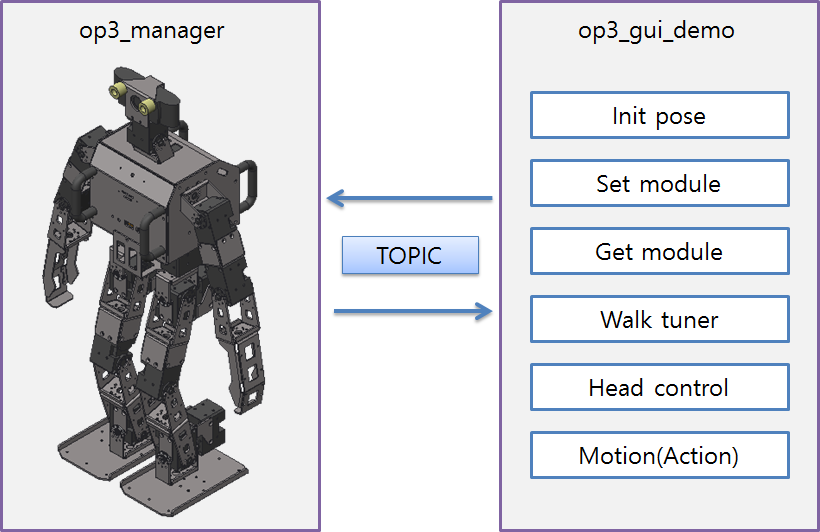
Reference : op3_gui_demo
Run the program
There are three options to run the GUI program.
- Connect input devices and display device directly to ROBOTIS-OP3 and run the GUI program on the robot.
- Use VNC from a remote PC to obtain control over the OP3 SBC(Intel NUC) and initiate the GUI program remotely.
-
Run the GUI program on a remote PC on the same ROS network with ROBOTIS-OP3.
Open the terminal window and enter the following command.
op3_managershould be running before executing GUI demo program.$ ros2 launch op3_gui_demo op3_demo.launch.pyReference : How to run op3_manager
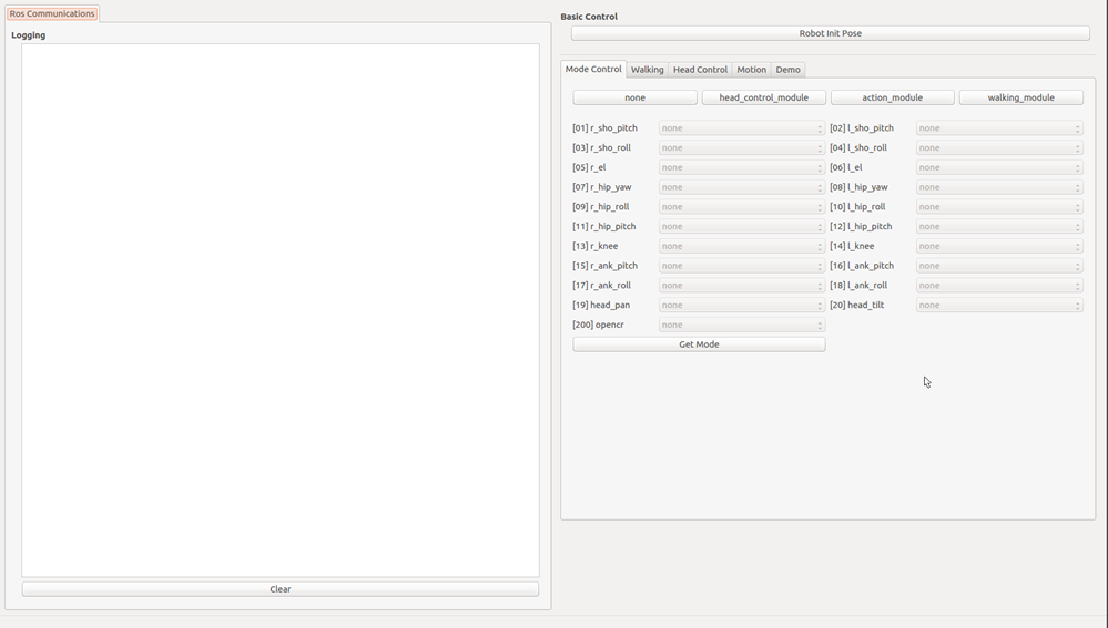
- Execution result
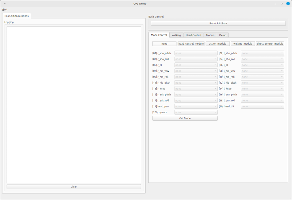
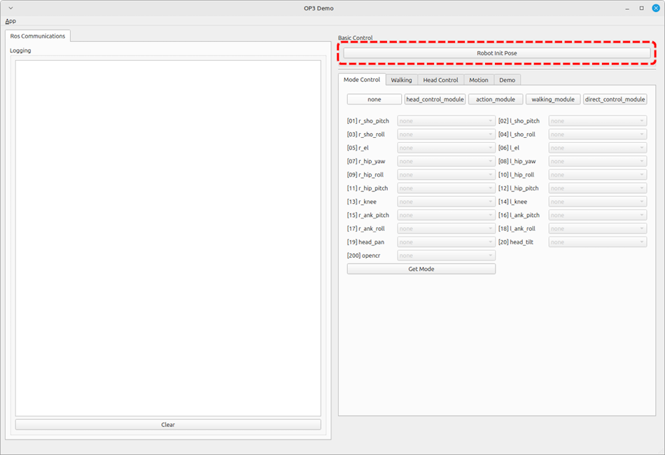
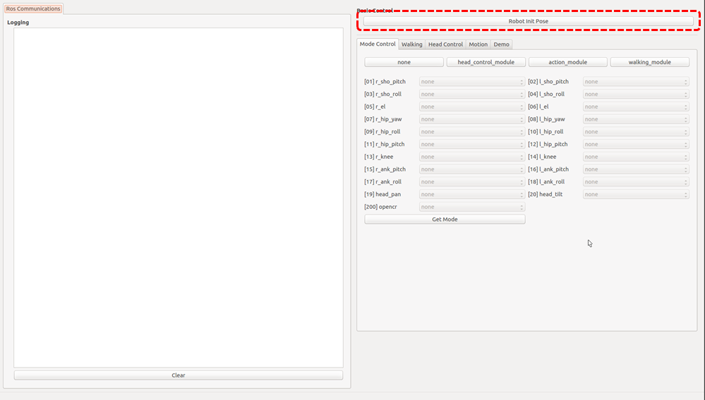
How to take the initial pose
Clicking the button surrounded by the red dashed rectangle will let the base_module control each joint of ROBOTIS-OP3 and move to the initial posture.
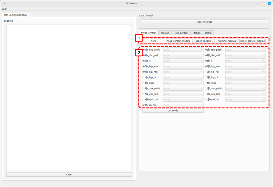
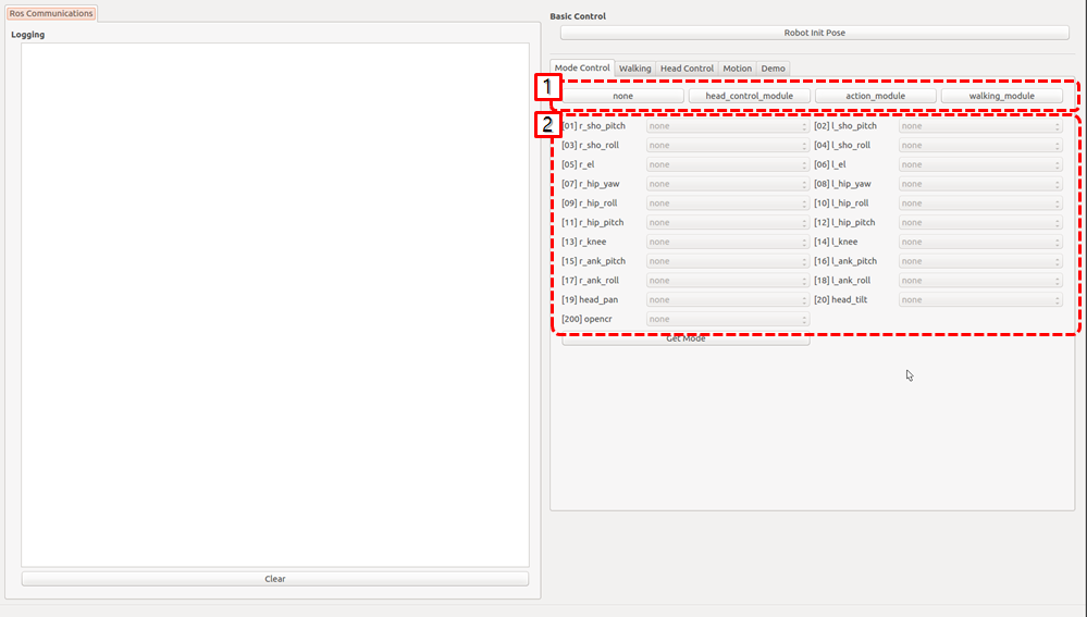
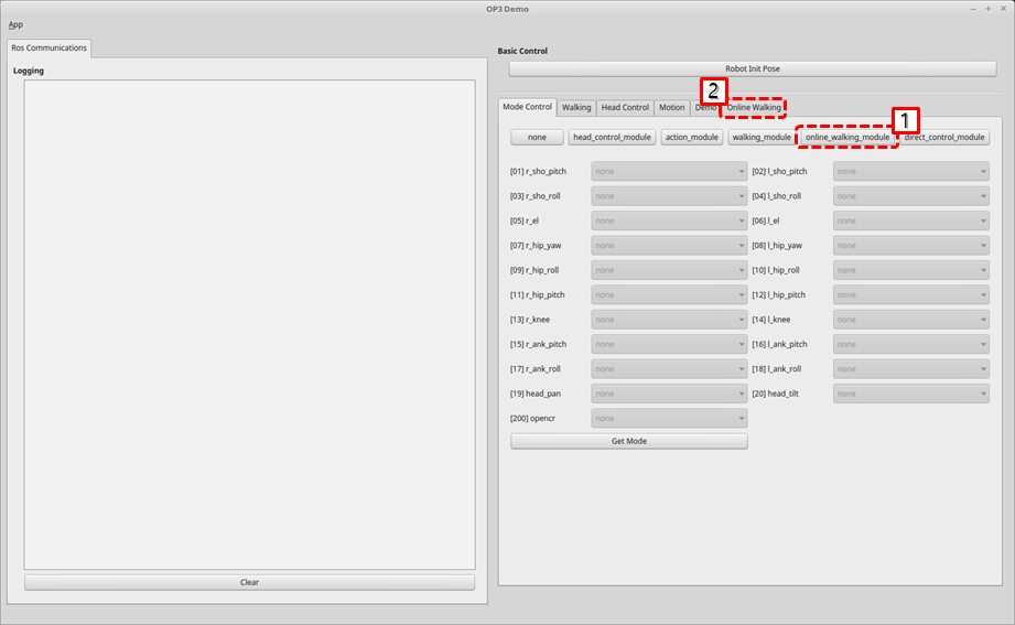
How to set the Module
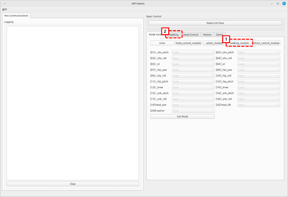
- Follow the below procedure to configure modules that control the corresponding joints of ROBOTIS-OP3.
-
Click the module button to configure.
-none
-head_control_module
-action_module
-walking_module
-direct_control_module -
Confirm from the joint status table below the module buttons that corresponding joints are set correctly.
-
-
Get Modebutton will report which module is assigned for each joint.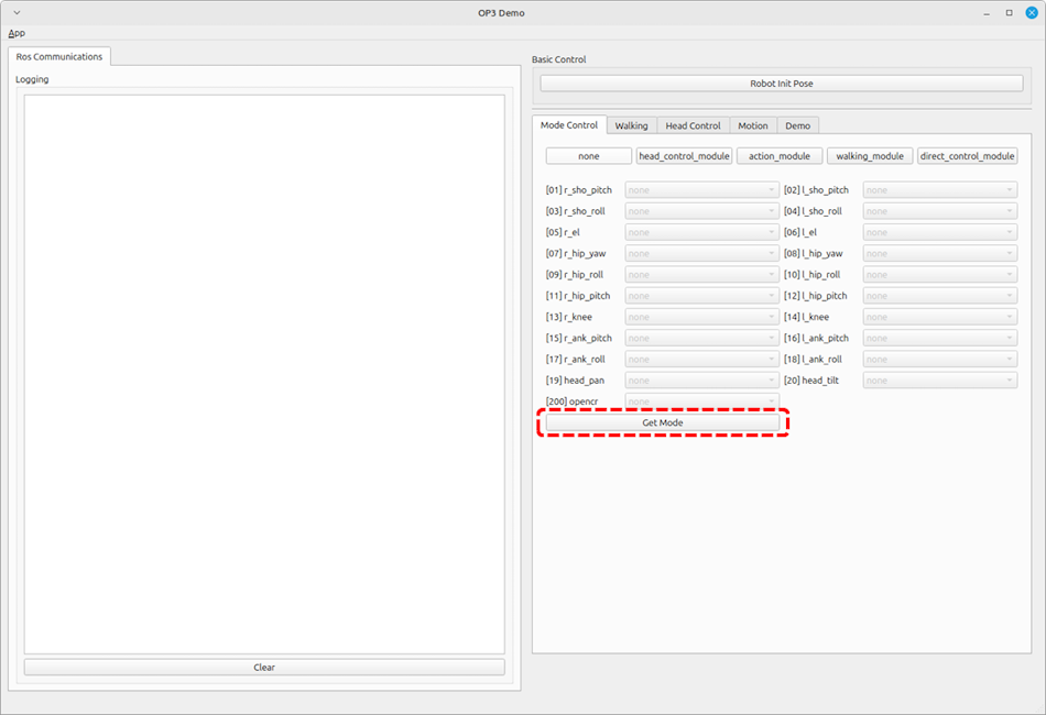
How to use walking tuner
Overview
This chapter explains how to configure walking parameters and test them with ROBOTIS-OP3.
The basic demo uses these saved walking parameters.
Description
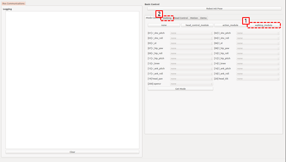
Setting Module
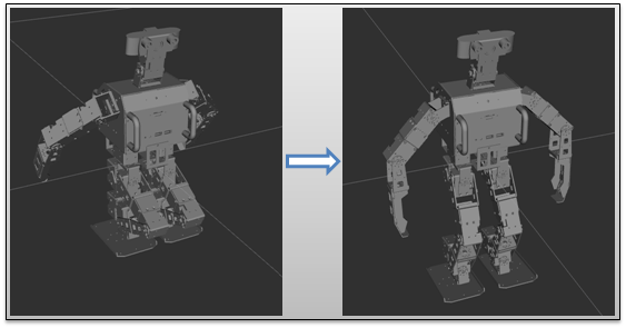
Activate walking_module on the lower body part of ROBOTIS-OP3 for walking test.
Confirm that the joints used for walking are set in the walking_module, then move to the Walking tab.
When the walking module is activated, ROBOTIS-OP3 will take the initial posture for walking.
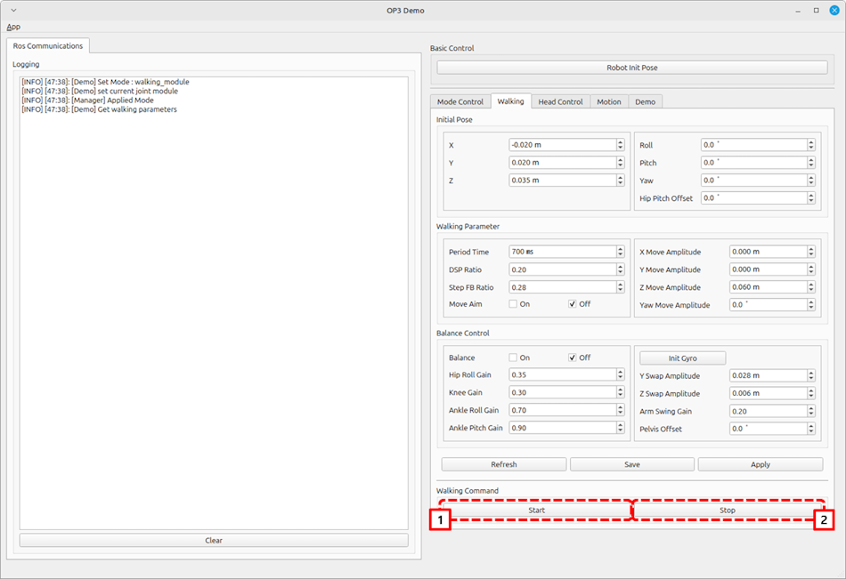
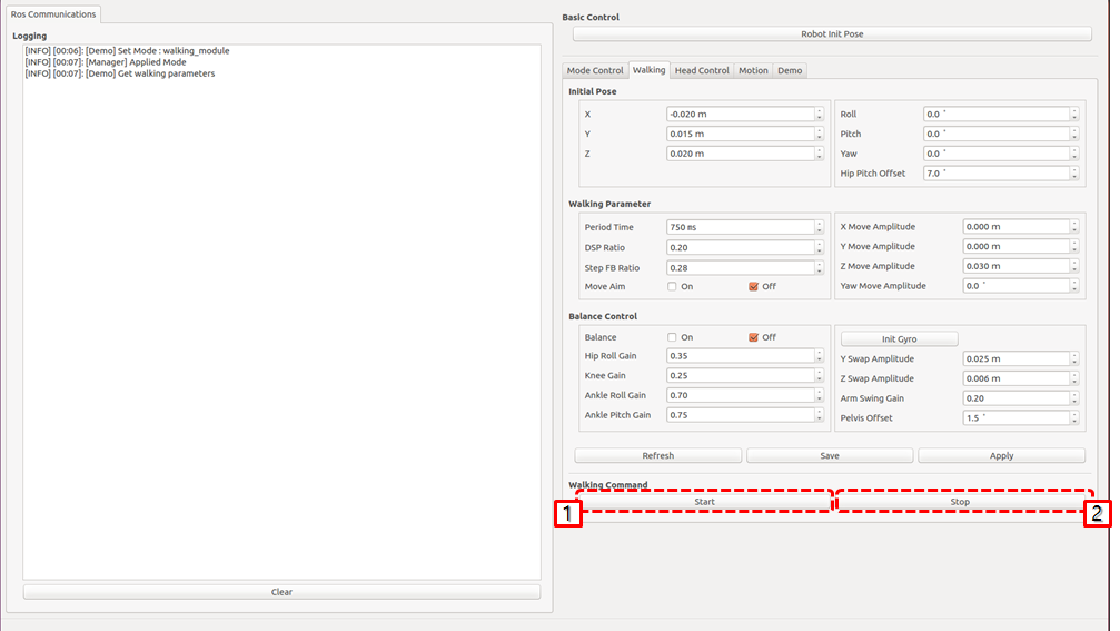
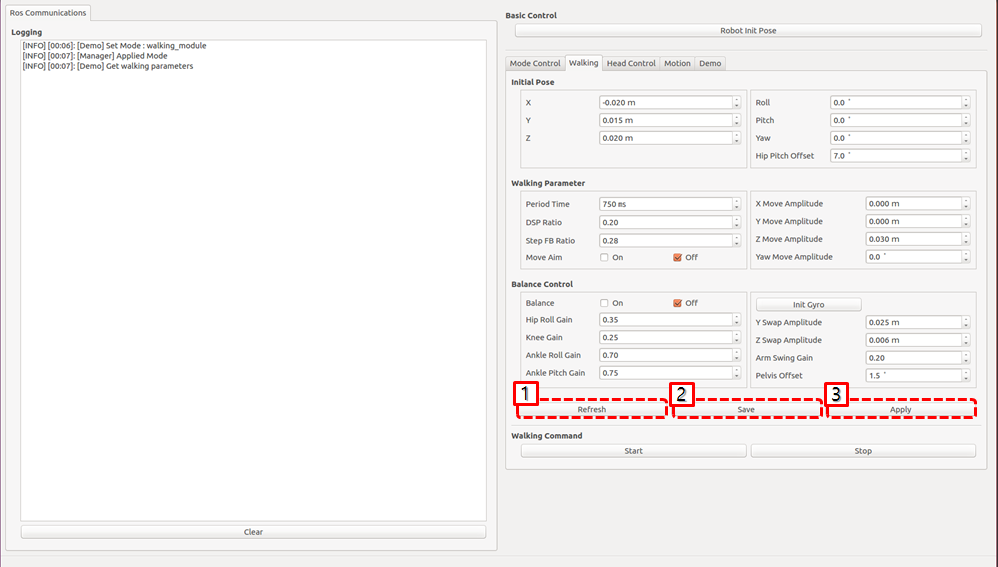
Start / Stop Walking
startbutton : Initiate walkingstopbutton : Stop walking. When stopped, walking related parameters will be reset.
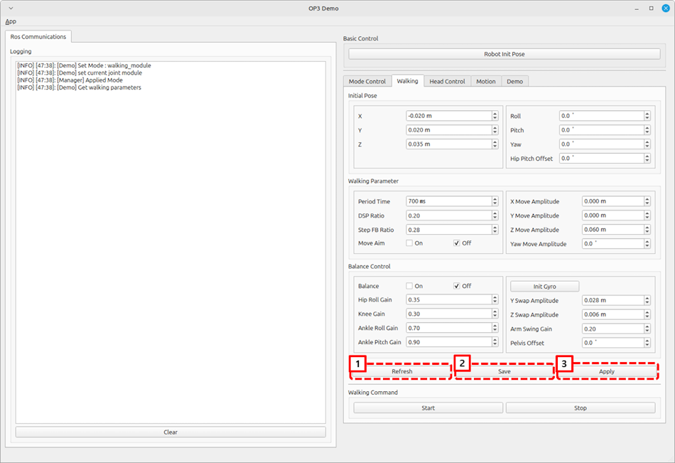
Apply Parameters
Refreshbutton : Acquire all parameters currently applied to thewalking_module.Savebutton : Save all parameters currently applied to thewalking_moduleas default parameters.Applybutton : Apply modified parameters from the GUI to thewalking_module.
How to play the motions
Overview
This chapter explains how to play predefined actions.
The action_module controls each joint of ROBOTIS-OP3.
Reference : op3_action_module
Description
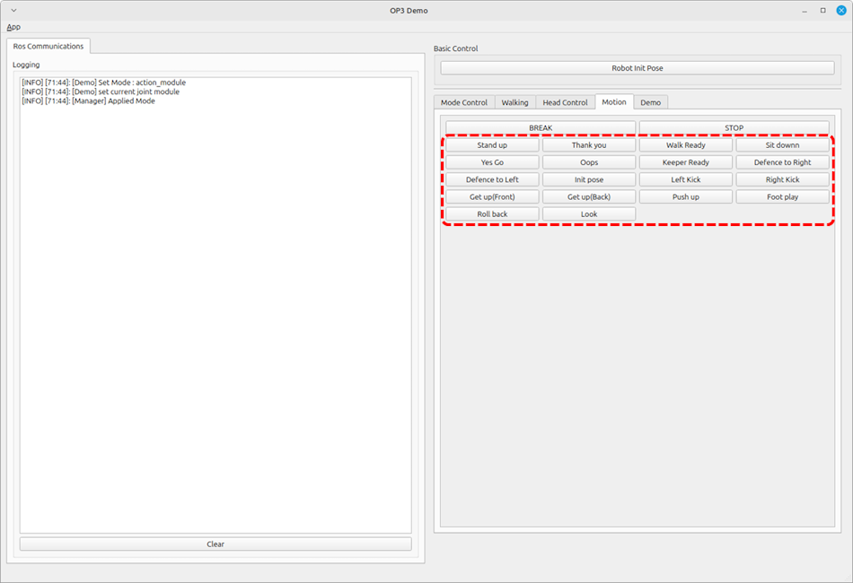
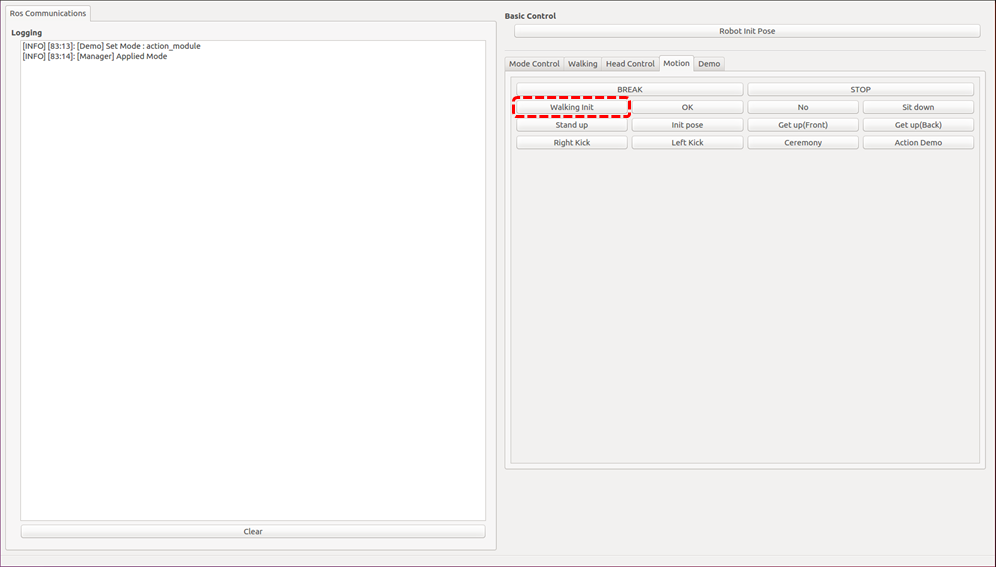
How to play
- Set the module : Press the
action_modulebutton. -
Select
Motiontab of the gui demo program.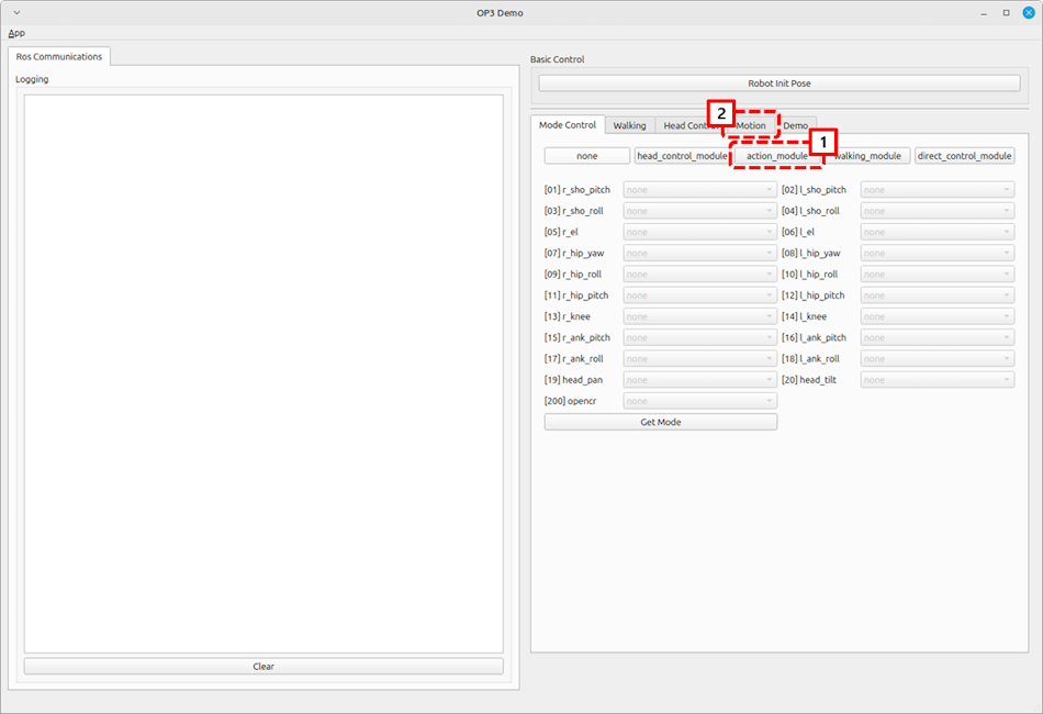
-
Click the action button to play
Creating and editing actions for action_module
Reference : How to create the motions
How to control the head joints
Overview
This chapter explains how to control the head joint of ROBOTIS-OP3.
The operator can get different camera view angles by controlling head joints.
Reference : op3_head_control_module
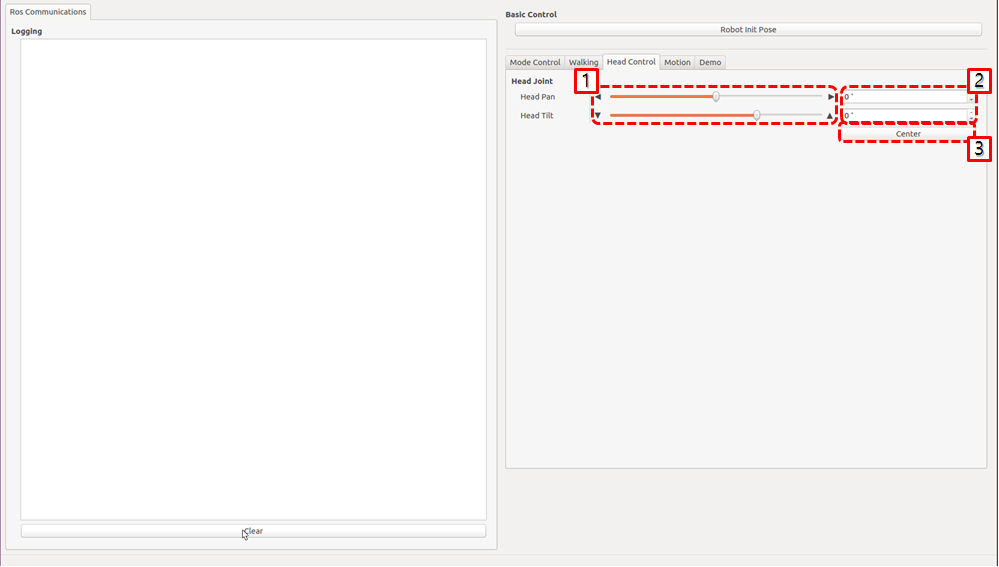
Head Joint Control
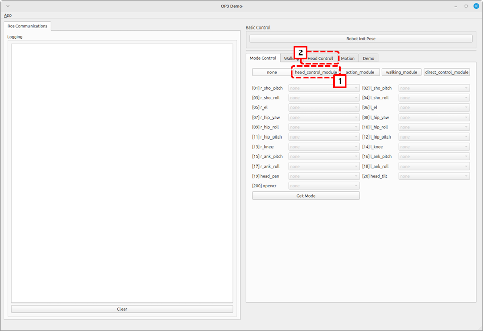
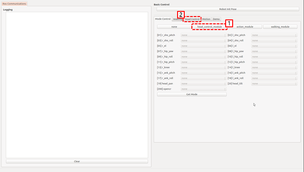
- Setting the Module : Click
head_control_modulebutton -
Select
Head Controltab of the gui demo program.
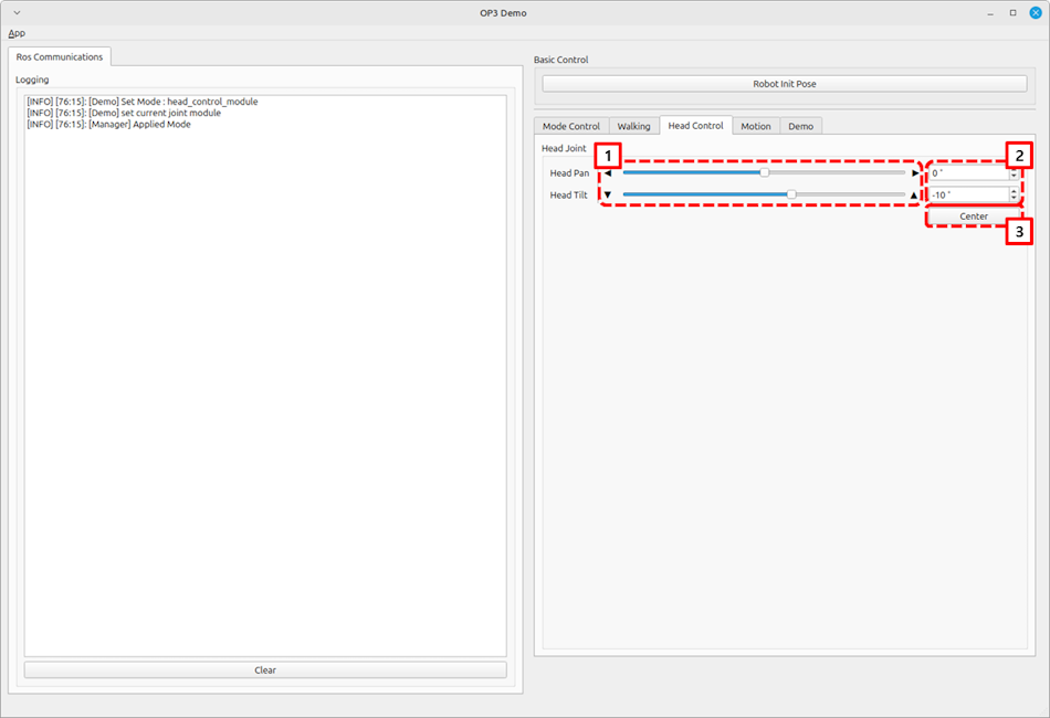
- Change the value for the specific joint.
- Use the slide bar to control the head joint.
- Enter desired values in the text box to control the head joint.
- Bring the head joint to center position.
How to control upgraded walking(online walking)
This version does not support this feature.
How to use offset tuner
Overview
deprecated
This chapter has been merged into How to use tuner client
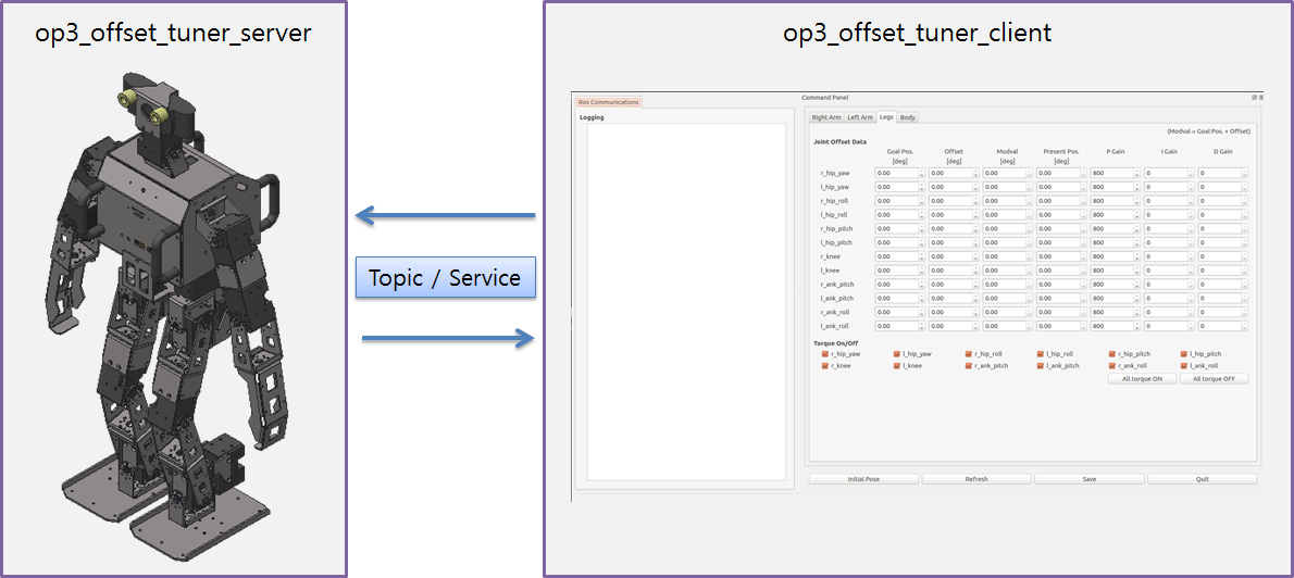
Reference : op3_offset_tuner_server
Reference : op3_offset_tuner_client
How to use tuner client
Overview
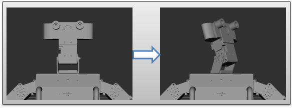
this chapter explains how to adjust kinematic offset and position gain of ROBOTIS-OP3. In the past, we were able to adjust the offset by using op3_offset_server and op3_offset_client. Now we can set both offset and gain using new op3_tuning_module and op3_tuner_client. We made an op3_tuning_module and used it with op3_manager, so you do not need to run the server just to tune the offset.
Reference : op3_tuning_module
Reference : op3_tuner_client
- Before
- After
Run Tuner Program
How to launch programs
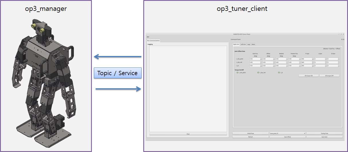
Launching op3_manager and op3_tuner_client program separately
The tuner consists of op3_manager and client programs so that other PC in the same ROS network can tune offsets and gains.
Execute the op3_manager first.
(Other programs such as op3_action_editor and op3_walking_tuner should be terminated to run the op3_manager).
$ ros2 launch op3_manager op3_manager.launch.py
After starting the op3_manager, execute client GUI program from the identical PC or any PCs in the same ROS network.
$ ros2 launch op3_tuner_client op3_tuner_client.launch.xml
Launching op3_manager and op3_tuner_client program at once
Enter the following commands in the terminal window.
(Other programs such as op3_action_editor and op3_walking_tuner should be terminated to run the offset tuner.)
$ ros2 launch op3_tuner_client op3_tuner.launch.xml
Configuration Files
op3_manager configuration files
- config/
OP3.robot: Contains the description of ROBOTIS-OP3. - config/
dxl_init_OP3.yaml: Stores DYNAMIXEL configurations, included gains, used for joint initialization. - config/
offset.yaml: Saves offset data.
op3_tuning_module configuration files
-
data/
tune_pose.yaml: Stores offset adjustment posture data and gain tuning posture data.init_pose: move_time: time # sec target_pose: joint_name: angle(degree) ... tune_pose_01: move_time: [time, time, ...] # sec target_pose: [pose_name, pose_name, ...] tune_pose_02: move_time: [time, time, ...] target_pose: [pose_name, pose_name, ...] tune_pose_03: move_time: [time, time, ...] target_pose: [pose_name, pose_name, ...] tune_pose_04: move_time: [time, time, ...] target_pose: [pose_name, pose_name, ...] pose_data: pose_name: joint_name: angle(degree) ...
op3_tuner_client configuration file
- config/
joint_data.yaml: GUI menu configuration file
How to use tuner client GUI program
How to tune the offset
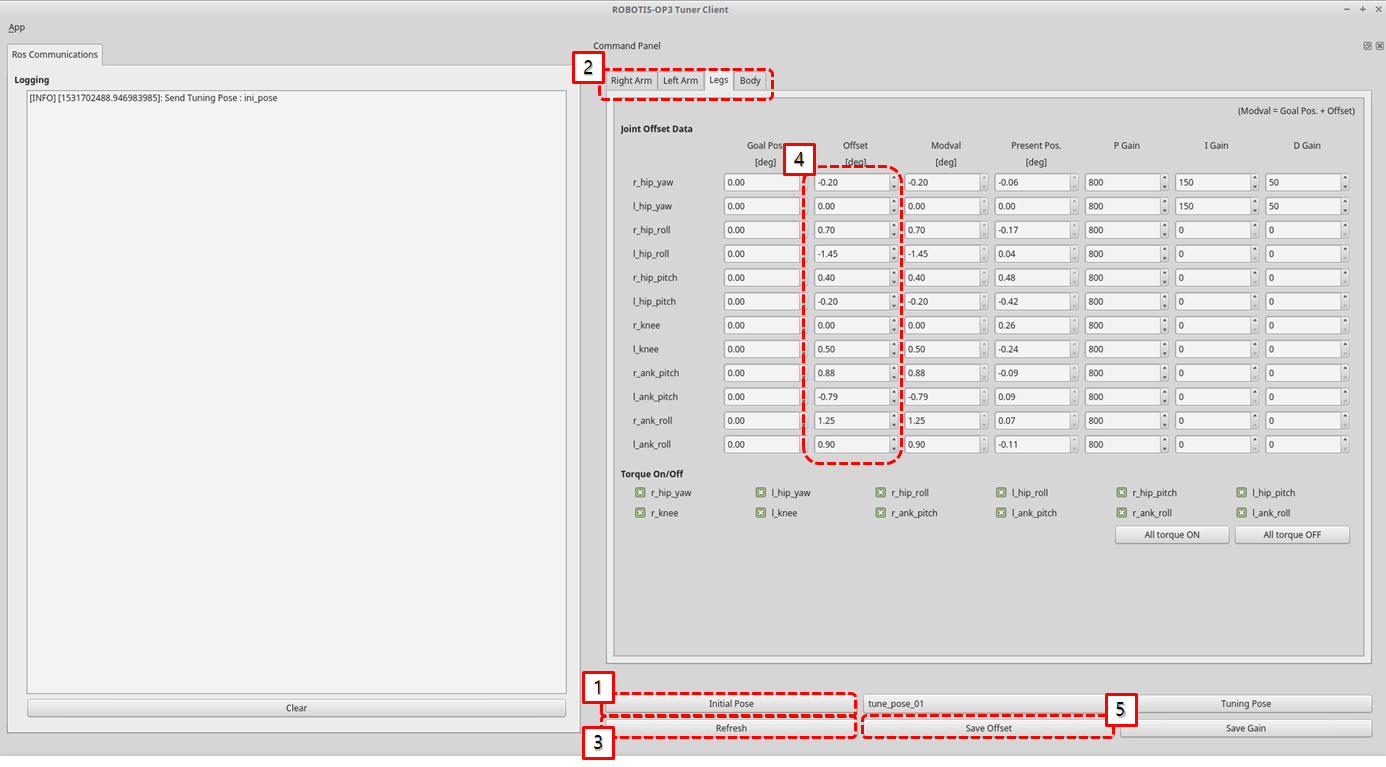
- Go to the
Initial Pose - Select the
Kinematics Grouptab - Click the
RefreshButton to update the current states of joints - Tune the offset of joints
- Click the
Save Offsetbutton for saving to file.
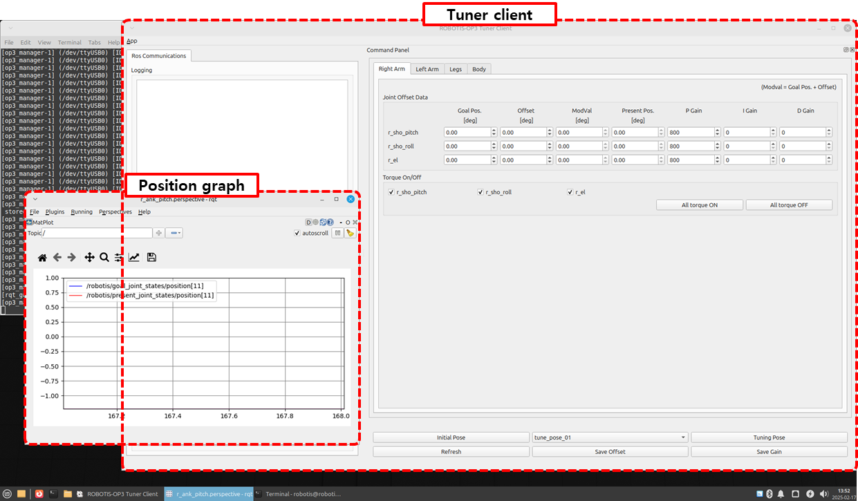
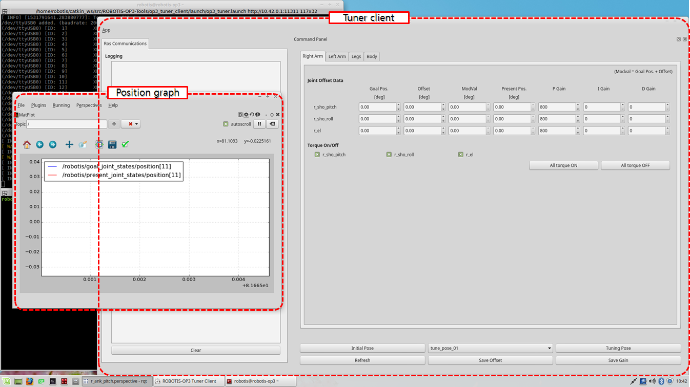
How to tune the gain
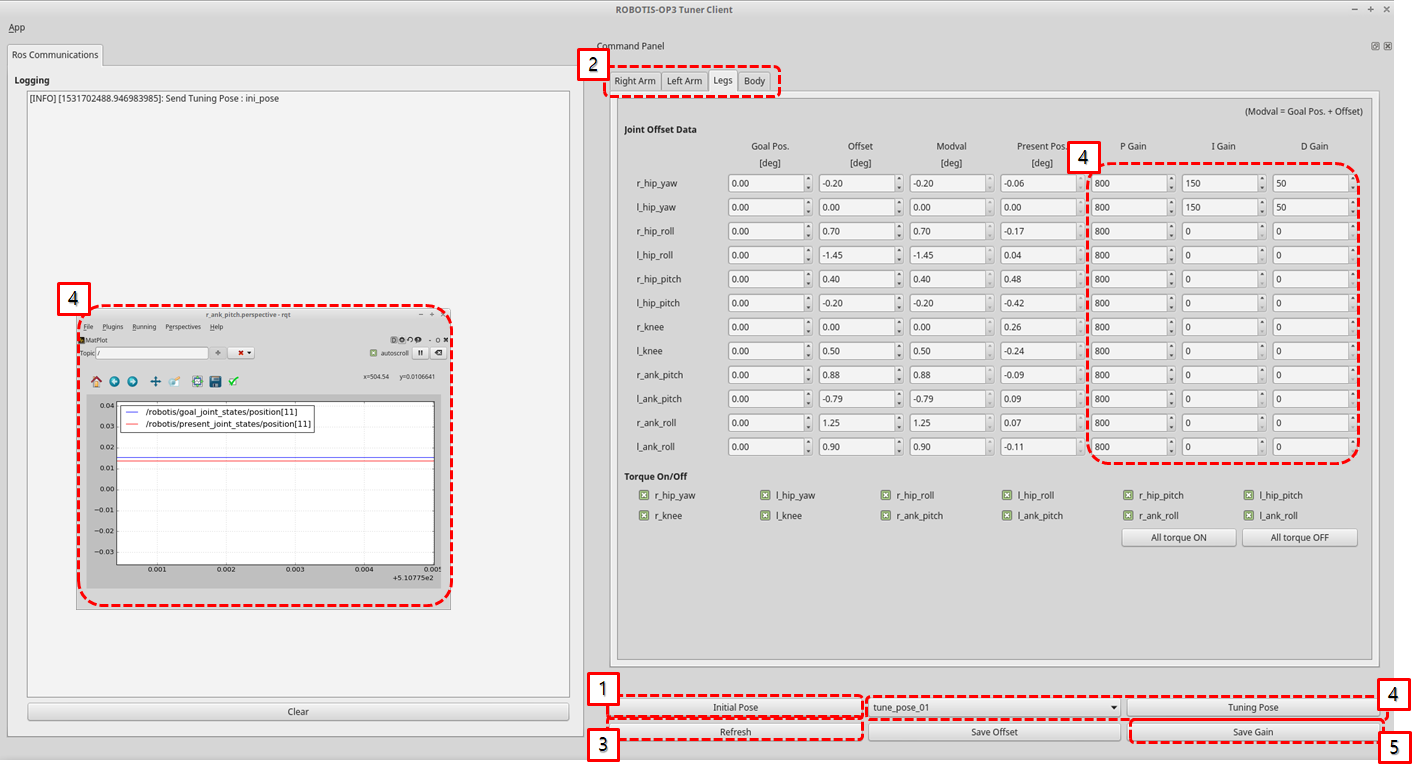
- go
Initial Pose - Select tab of
Kinematics Group - Click the
RefreshButton for getting current states of joints - change the pose and tune the gain of joints for watching the graph of the joint
(If you want to tune other joint, delete topics and add topics that you want to tune) - Click the
Save Gainbutton for saving to file.
Reference : Order of the joint name in the topic(
/robotis/goal_joint_states)
  0 : haed_pan
  1 : haed_tilt
  2 : l_ank_pitch
  3 : l_ank_roll
  4 : l_el
  5 : l_hip_pitch
  6 : l_hip_roll
  7 : l_hip_yaw
  8 : l_knee
  9 : l_sho_pitch
  10 : l_sho_roll
  11 : r_ank_pitch
  12 : r_ank_roll
  13 : r_el
  14 : r_hip_pitch
  15 : r_hip_roll
  16 : r_hip_yaw
  17 : r_knee
  18 : r_sho_pitch
  19 : r_sho_roll
Use the following command to check the saved values
$ ros2 topic echo /robotis/goal_joint_states --once
How to create the motions
Overview
ROBOTIS-OP3 Action Editor Node.
This chapter explains how to create and edit action files used in the op3_action_module of ROBOTIS-OP3.
Action File
The action file contains ROBOTIS-OP3’s poses and time data. The Current position describes positions of DYNAMIXEL, which are converted from the actual DYNAMIXEL resolution to a 4,095 resolution. The action file is written as a binary file, so users can read its contents with op3_action_editor. ROBOTIS currently provides a default action file with the source code. It is located in the op3_action_module/data directory.
The action file contains 256 pages. Each page can store up to 7 stages (or steps) of action data. The default action file does not use all pages, and users can add their own actions by writing them to the empty pages.
Getting started
Download & Build
Reference : Installing ROBOTIS ROS Package
Run
Run the executor file.
op3_action_editor has direct control over ROBOTIS-OP3, other control programs such as op3_manager, op3_offset_tuner and op3_walking_tuner should not be running.
$ ros2 run op3_action_editor executor.py
UI
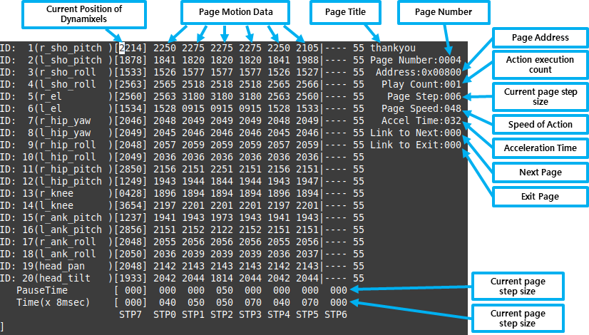
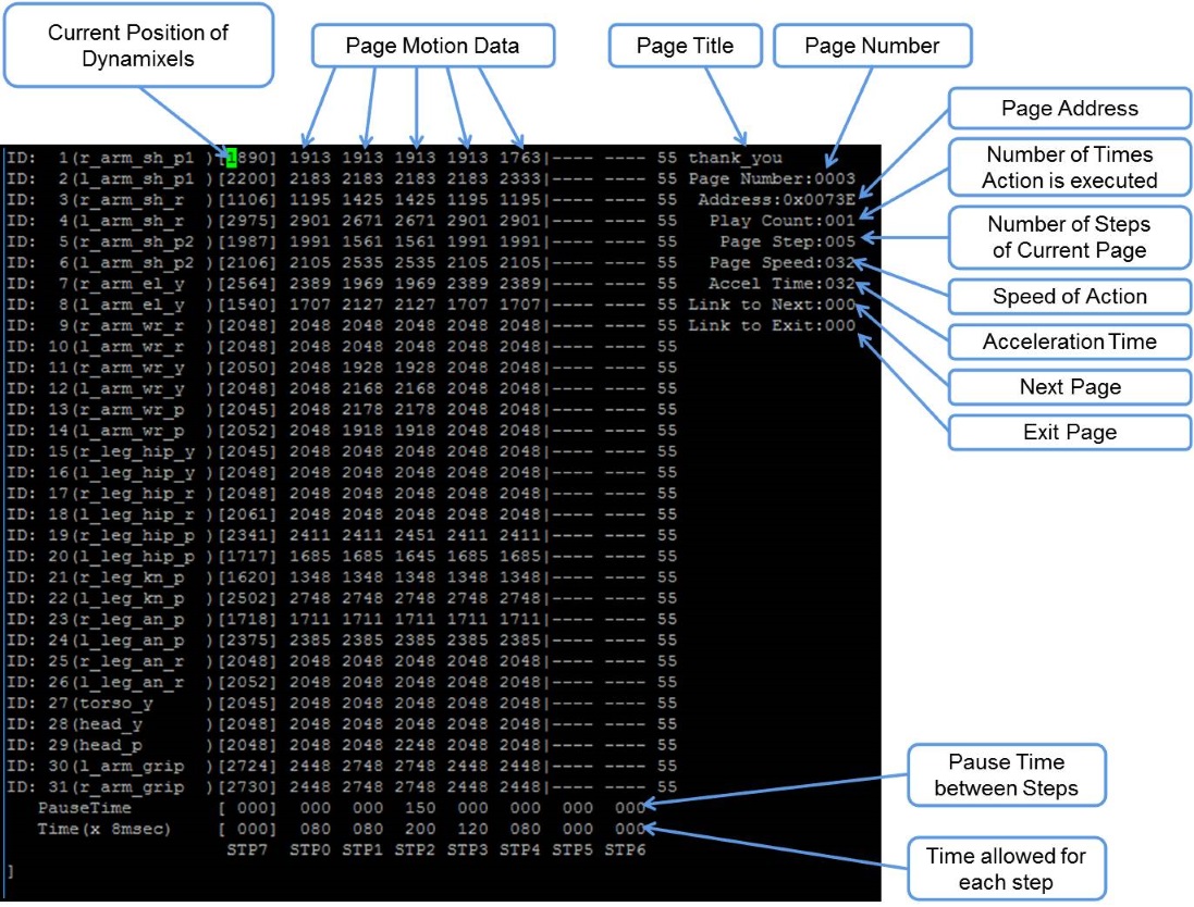
- Page number: Page number is the listed page number. If user wants to create a new action pose, the user can use any empty page.
- Page title: ROBOTIS recommends the use of a page title when creating a new action on an empty page.
- Current position: The current position describes position of DYNAMIXEL which converted from actual DYNAMIXEL resolution to 4,095 resolution. This data is represented by STP7 in op3_action_editor. Sometimes the position may be read as —- in op3_action_editor. This means position of DYNAMIXEL has not been read (or torque is off).
If user turns DYNAMIXEL off, current position cannot be read until turn it back on.
User can turn off the torque of specific DYNAMIXEL. This is very convenient when acquiring position values directly from DYNAMIXEL for a new robot posture instead of calculating those values. To do that, turn off the torque of desired DYNAMIXEL, then make a posture and hold the robot joint by hand until turn the torque back on. The robot will be remaining at current posture and user can read position values of corresponding DYNAMIXEL. - Steps or stages: Each page can store up to 7 steps, from STP0 to STP6. However, some actions may be required more than 7 stages to perform completely. This can be resolved by simply using multiple pages and link them with Next
- Next: Next indicates whether to continue action on a different page. To continue actions, just list the page number where the action is to be continued. Number 0 indicates that action does not continue onto another page (default value). Linking page does not have to have the numerical order.
- Play Count: The number of times the page’s action will be executed.
- Exit: There might be some cases when an action has to be stopped. In these cases, the robot may be in unstable position. Exit is much like “Next”, so “Exit” should be linked to a page where ROBOTIS-OP3 can return to a stable pose. If “Exit” is 0, it means that there is no linked exit page (default value).
Tip: When calling an action requires multiple pages, ROBOTIS strongly suggests user to call the action from the starting page. For example, clap starts at page 7 and ends at page 8. This means you should call page 7 when calling clap. Calling the page 8 may cause unexpected behavior of the robot. - STP7: “STP7” column is the current position of DYNAMIXEL which converted to 4,095 resolution from its original resolution. “—-“ means that torque has been released.
- PauseTime: “PauseTime” is the pause duration period for motion playback for step STP[x].
- Time(x 8msec) : “Time” is the time period for ROBOTIS-OP3 to complete step STP[x]. Each time unit account for 8ms of time.
It is strongly advised that when user tests user’s own newly-created or edited actions, there should be small incremental changes in position, speed/time, and pause values for the sake of ROBOTIS-OP3’s stability.
The Contents of The Default Action File
The below table shows the contents of the default action file.
| page number | page title | brief description of page | number of pages |
|---|---|---|---|
| 1 | standup | Standing-up | 1 |
| 4 | thankyou | Thank you | 1 |
| 9 | walkready | Walking-ready | 1 |
| 15 | sit down | Sitting-down | 1 |
| 23 | yes go | Yes Go | 1 |
| 24 | wow1 | Wow | 2 |
| 27 | oops | Oops | 1 |
| 38 | bye1 | Bye | 2 |
| 41 | talk2 | Introduction | 7 |
| 54 | clapplz1 | Clap please | 2 |
| 60 | keep_re | Keeper Ready | 1 |
| 61 | keep_r | Defence to Right | 1 |
| 62 | keep_l | Defence to Left | 1 |
| 80 | walk_ready | Soccer Init pose | 1 |
| 120 | l_kick_170519 | Soccer Left Kick | 1 |
| 121 | r_kick_170519 | Soccer Right Kick | 1 |
| 122 | f_get_up | Get up (Front) | 1 |
| 123 | b_get_up | Get up (Back) | 1 |
| 126 | push up | Push-up | 4 |
| 202 | b_getup_dumb | Roll back | 1 |
| 204 | see_right_up | Look | 1 |
Basic Command of Action Editor
After typing “help”, the commend list will appear as shown below.
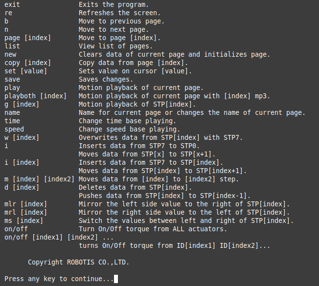
- exit: exits the program.
- re: refreshes the screen.
- b: moves to the previous page.
- n: moves to the next page.
- page [index]: moves to the [index] page. For example typing page 5 outputs data from page 5 on screen.
- list: outputs a list of pages.
- new: initializes current page by clearing all actuator position data.
- copy [index]: copies data from page [index] to current page. For example if you are on page 5 and want to copy page 9 then type copy 9.
- set [value]: sets position value on chosen actuator. For example If you want ID19 (head pan) to have a value of 512 then using the keyboard’s directional keys place the cursor on ID19 and type set 512.
- save: saves any changes you’ve made. the saved motion file (motion_4096.bin can be found at “op3_action_module/data”)
- play: plays motion(s) of current page.
- playboth [index]: plays motion(s) of current page with [index] mp3.
- g [index]: plays motion of STP[index].
- name: changes the name of the current page. You can view the name of the page at the top right portion of the screen. For example, page 2 is titled hello; to change the name type name and press the “ENTER” key. “name:” will appear at the bottom of the screen. Input the desired name for the page, good for instance, and press the “ENTER” key again.
- time: change time base playing.
- speed: change speed base playing.
- w [index]: overwrites the data of STP[index] with the data of STP7(current pose).
- i: inserts data from STP7 to STP0. Moves data from STP[x] to STP[x + 1] if any.
- i [index]: inserts data from STP7 to STP[index]. Moves data from STP[index] to STP[index + 1] if any.
- m [index] [index2]: moves data from [index2] to [index].
- d [index]: deletes data from STP[index]. Moves data from STP[index] to STP[index - 1].
- mlr [index]: mirrors the left-side values of STP[index] to the right-side values.
- mrl [index]: mirrors the right-side values of STP[index] to the left-side values.
- ms [index]: swaps the left and right values of STP[index].
- on/off: turns on/off torque from all DYNAMIXEL.
- on/off [index1] [index2] [index3] … : turns torque on/off from ID[index1] ID[index2] ID[index3]. For example off 20 releases torque from ID20. Notice that STP7 for ID20 will read [—-]. Typing on 20 turns torque from ID20 on again and the screen outputs the current position data of ID20.
Example Action editing with op3_action_editor
- Run the op3_action_editor
-
Type
listto find where thewalkreadypage is located.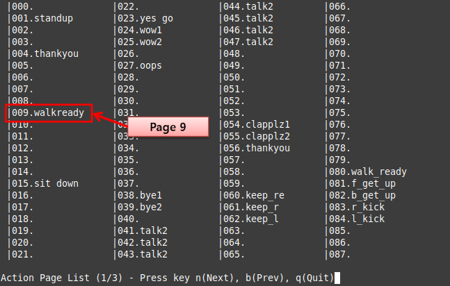
-
Exit the list and go to any blank page by typing
page [x](for example, page 12).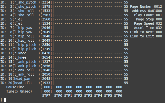
-
And copy the page 9 to page [x] by typing
copy 9.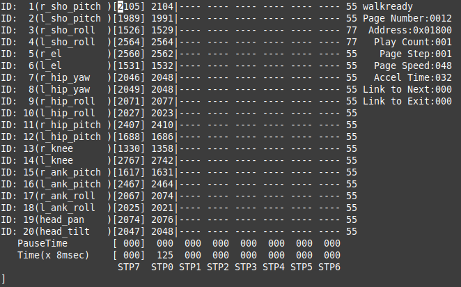
- Go to
walkreadypose by typingplay -
Turn off the torque of ID 2, 4 and 8 by typing
off 2 4 8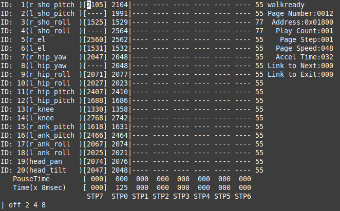
-
After getting the desired pose turn torque on again by simple typing
on. And insert the pose to step 1 by typingi 1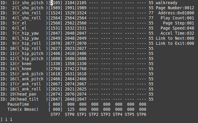
-
Edit
Pause Time,Timeof STP1 andPage Stepas shown below.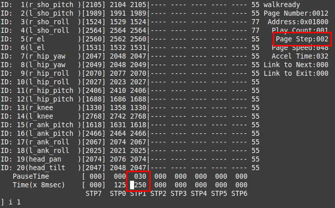
- Type
playand check the ROBOTIS-OP3’s action
How to use ball detector
Overview
This chapter explains how to calibrate the ball_detector_node to find a ball. The ball_detector_node detects a ball by the designated color and Hough Circle Transform.
Getting started
Run the program
$ ros2 launch op3_ball_detector ball_detector_from_usb_cam.launch.py
or
$ ros2 launch op3_demo demo.launch.xml
How to change the parameters
- Dynamic Reconfigure and Image View
-
run the
rqt$ rqt -
Open
Dynamic Reconfigure
SelectPlugins -> Configuration -> Dynamic Reconfigure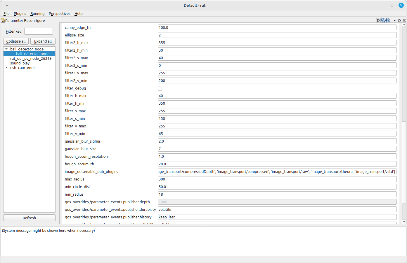
-
Open
Image View
SelectPlugins -> Visualization -> Image View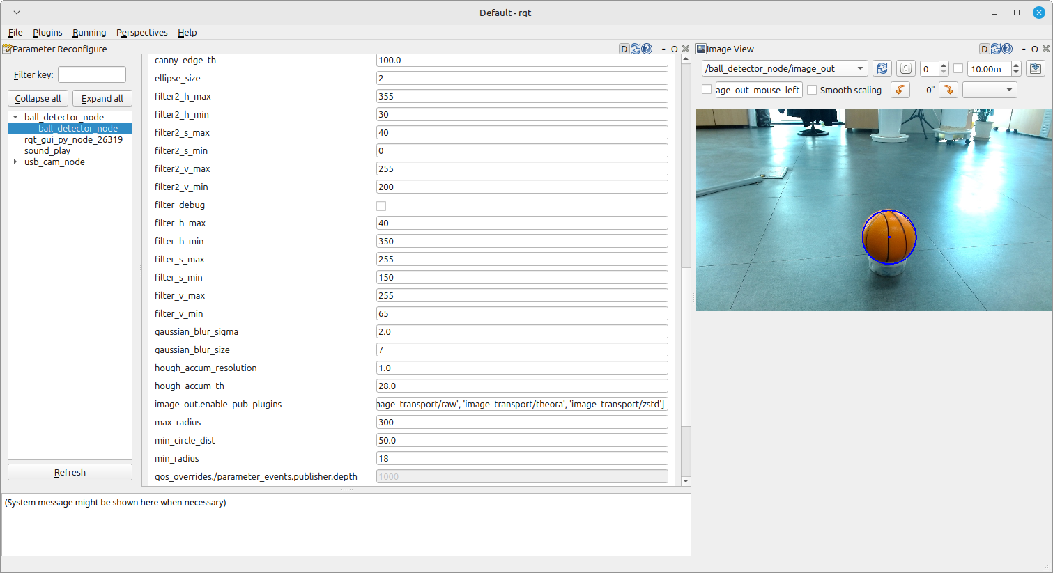
-
- Parameters
- canny_edge_th: Threshold of the edge detector
- ellipse_size: Ellipse size
- gaussian_blur_sigma: Std deviation of Gaussian Blur
- gaussian_blur_size: Size of Gaussian Blur Kernel (odd value)
- hough_accum_resolution: Resolution of the Hough accumulator, in terms of inverse ratio of image resolution
- hough_accum_th: Accumulator threshold to decide center detection
- min_circle_dist: Minimum distance between circles
- min_radius: Minimum circle radius allowed, pixels. (if unknown, put 0 for a detault.)
- max_radius: Maximum circle radius allowed, pixels. (if unknown, put 0 for a detault.)
- filter_h_min: Minimum threshold of H filter
- filter_h_max: Maximum threshold of H filter
- filter_s_min: Minimum threshold of S filter
- filter_s_max: Maximum threshold of S filter
- filter_v_min: Minimum threshold of V filter
- filter_v_max: Maximum threshold of V filter
- use_second_filter: Use second filter
- filter2_h_min: Minimum threshold of H filter
- filter2_h_max: Maximum threshold of H filter
- filter2_s_min: Minimum threshold of S filter
- filter2_s_max: Maximum threshold of S filter
- filter2_v_min: Minimum threshold of V filter
- filter2_v_max: Maximum threshold of V filter
- debug_image: Show filtered image to debug
- Description
-
How the ball_detector_node works
ball_detector_node filters the HSV value first, then detect the ball withHoughCircles -
How to calibrate
-
Set H(hue) value (color value) first with full range of S and V. Then set the range of S(saturation) and V(value) to remove the noise.
Hueis measured by degrees within the cylindrically represented color system. Therefore, the value 360 can be represented as 0, and the minimum value can have a bigger number than the maximum value. (ex : min - 350 / max - 10 [Red area]) -
If you check the
use_second_filteryou can get an image which is detected with two HSV variations.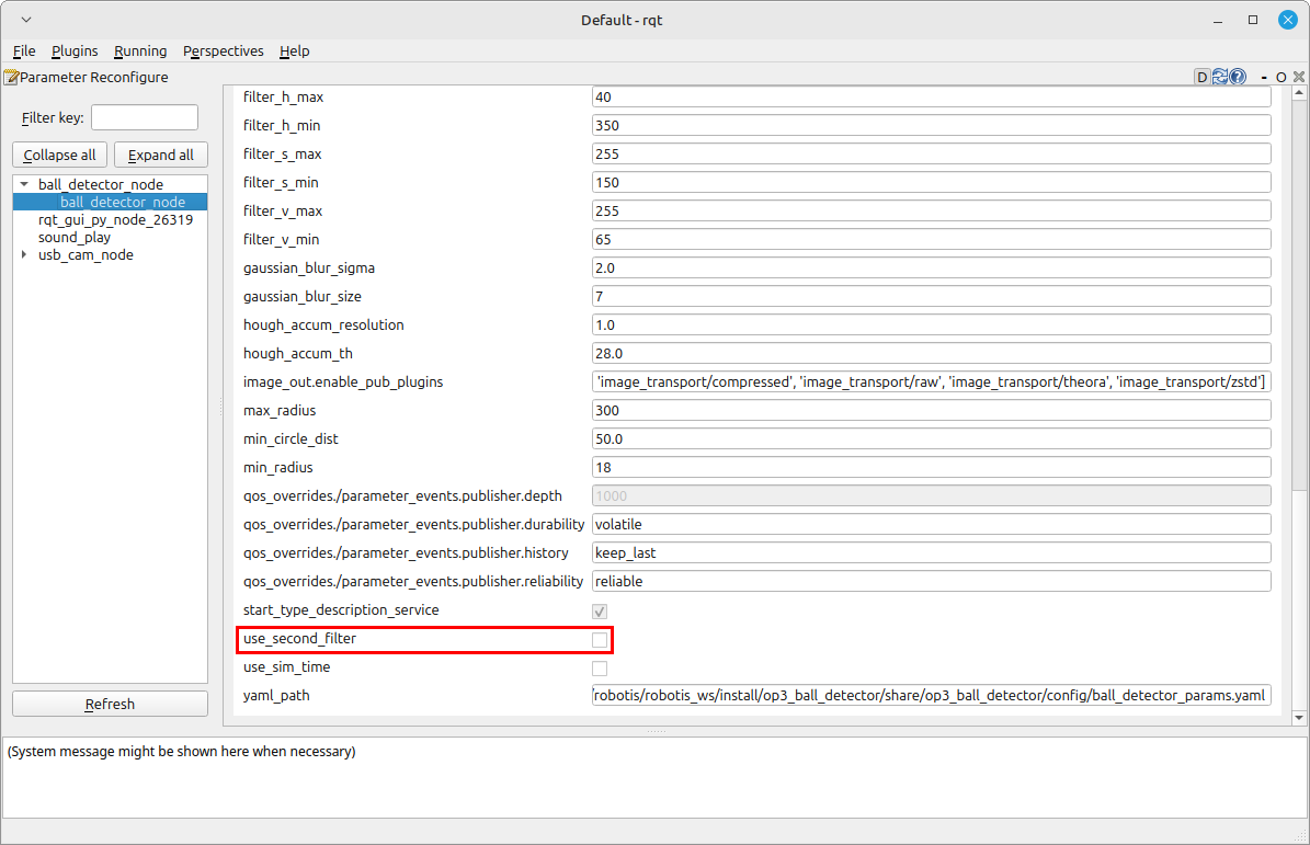
-
If you check the
debug_imageyou can check the HSV filtered, binary image.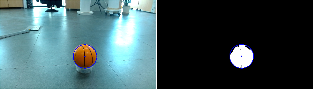
-
After you set the HSV range, you could calibrate the threshold value to detect the edge better.
-
-
How to control upgraded walking using footstep planner
This version does not support it.
How to use Web Setting Tool
Overview
This chapter explains how to set the parameters of ROBOTIS-OP3 through a web page.
Reference : ROBOT WEB TOOL
Reference : web_video_server - ros2
Reference : rosbridge_suite - ros2
Getting started
Installation
- web_video_server
$ sudo apt install ros-jazzy-web-video-server - rosbridge_server
$ sudo apt install ros-jazzy-rosbridge-server - Update and build source
- ROBOTIS-OP3-Demo
$ cd ~/robotis_ws/src/ROBOTIS-OP3-Demo $ git pull - ROBOTIS-OP3-Tools
$ cd ~/robotis_ws/src/ROBOTIS-OP3-Tools $ git pull - Build source
$ cd ~/robotis_ws
$ colcon build --symlink-install
- ROBOTIS-OP3-Demo
- Setup the Web Server
- Install web server(APACHE2)
$ sudo apt install apache2 - Check the default page from a web browser
- http://10.42.0.1
- Install web server(APACHE2)
- Copy files from ROBOTIS-OP3-Tools folder to the web server folder : github
$ cd ~/robotis_ws/src/ROBOTIS-OP3-Tools/op3_web_setting_tool
$ sudo cp -r ./html /var/www
How to connect ROBOTIS-OP3 WiFi
Connect to ROBOTIS-OP3 WiFi with below information
- WiFi ssid : ROBOTIS-OP3-Share
-
password : 11111111
For security reasons, it is recommended to change the WiFi password.Reference : How to connect
How to run web setting tool
- How to run the packages manually for web server
$ ros2 launch op3_web_setting_tool web_setting_server.launch.xml
How to set parameters
Menu
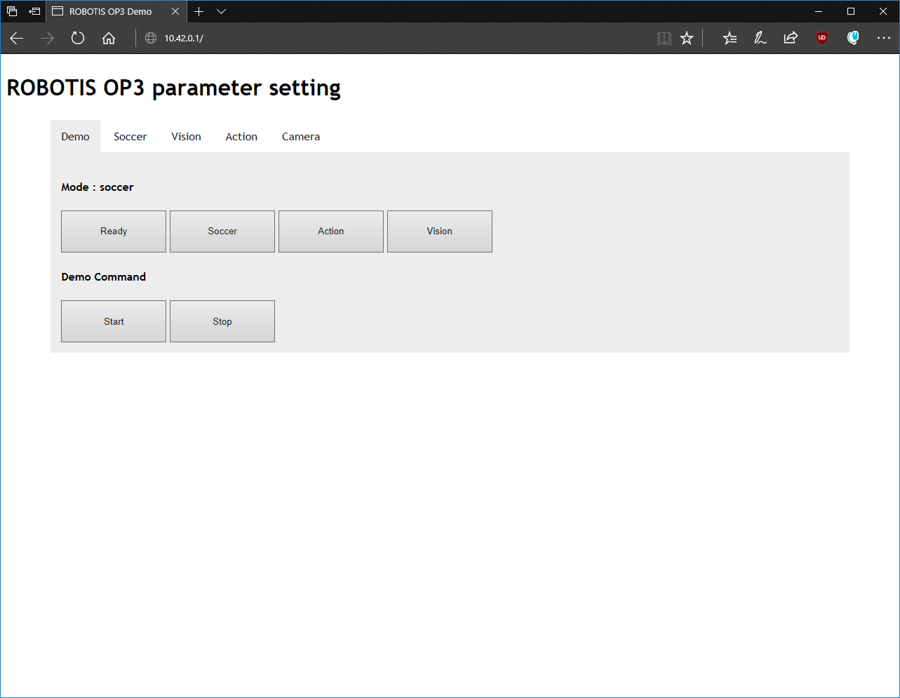
- Demo : Control default demo of ROBOTIS-OP3.
- Soccer : Setting for ball_detector.
- Vision : View the status of the detected face.
- Action : Testing ROBOTIS-OP3 actions.
- Camera : Change the parameters of ROBOTIS-OP3 camera.
Ball Detector parameters
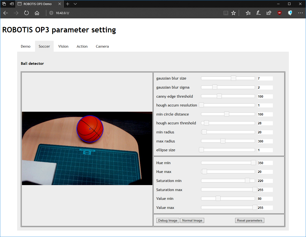
Modified parameter values will be saved automatically.
- gaussian blur size: Size of Gaussian Blur Kernel (odd value)
- gaussian blur sigma: Standard deviation of Gaussian Blur
- canny edge threshold: Threshold of the edge detector
- hough accum resolution: Resolution of the Hough accumulator, in terms of inverse ratio of image resolution
- min circle distance: Minimum distance between circles
- hough accum threshold: Accumulator threshold to decide center detection
- min radius: Minimum circle radius allowed, pixels. (if unknown, set to 0 as a default.)
- max radius: Maximum circle radius allowed, pixels. (if unknown, set to 0 as a default.)
- ellipse size: Ellipse size
- Hue min: Minimum threshold of H filter
- Hue max: Maximum threshold of H filter
- Saturation min: Minimum threshold of S filter
- Saturation max: Maximum threshold of S filter
- Value min: Minimum threshold of V filter
- Value max: Maximum threshold of V filter
- Debug image: Show filtered image to debug
- Normal image : Show normal image
- Reset parameters : reset all of parameters
Reference : detail of parameter
Camera Setting parameters
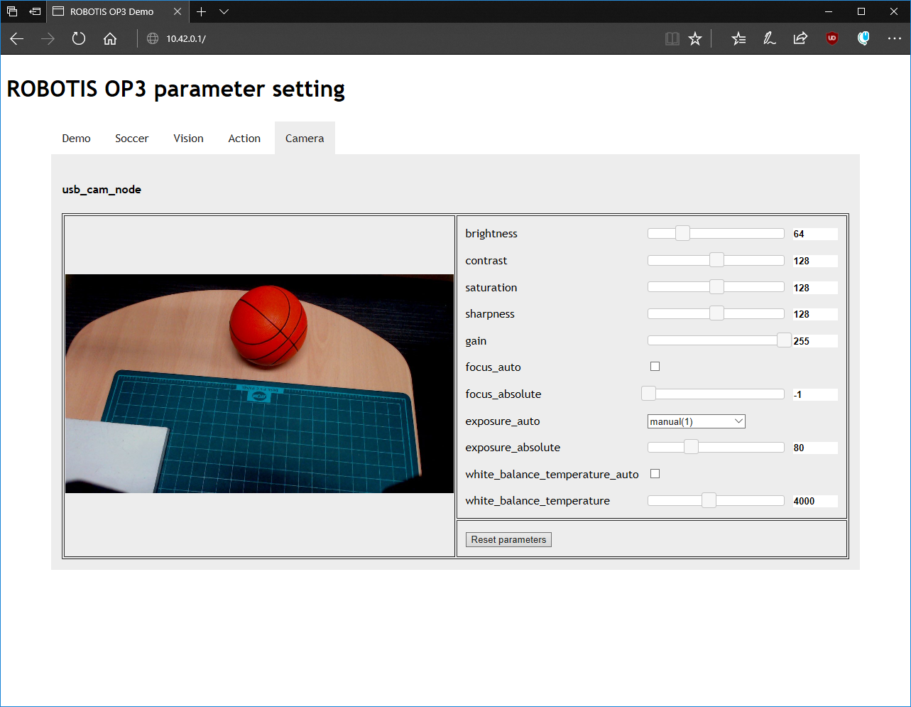
Modified parameter values will be saved automatically.
Read-Write Tutorial
Overview
This chapter explains to user how to get joint angles of ROBOTIS-OP3 and how to set their values.
Framework Diagram
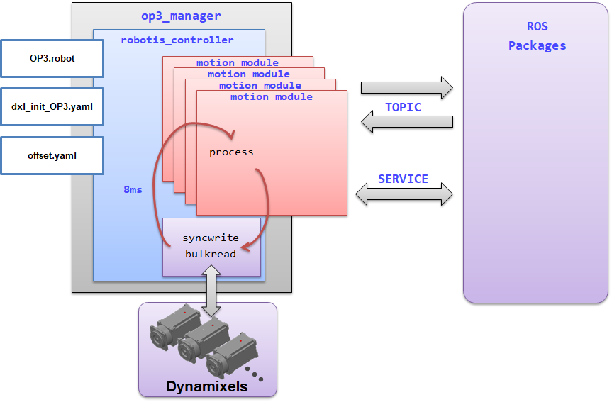
This is a framework diagram. The framework(op3_manager) works in the following way.
- Initialization
- Add sensors and motion modules
-
Start the timer and run threads
Execute the process function within the thread at a cycle of 8ms.
The process function performs the following operations according to the mode.-
DirectControlMode : This mode directly controls the robot using topics received from the user.
- BulkRead RX : Received rx packet containing joint information of each DYNAMIXEL
- SyncWrite : Transmit joint values to the multiple DYNAMIXEL’s to control
- BulkRead TX : Transmit tx packet to get information of dynamixel
- Call
process()function of each sensor module - Publish a topic that contains present & goal joint states
-
MotionModuleMode : This mode controls the robot using motion module.
- BulkRead RX : Received rx packet containing joint information of each DYNAMIXEL
- SyncWrite : Transmit goal values(position, velocity, current, position PID gain, velocity PID gain) to multiple DYNAMIXEL’s
- BulkRead TX : Transmit tx packet to get information of dynamixel
- Call
process()function of each sensor module - Call
process()function of each motion module - Publish a topic that contains present & goal joint states
-
Description
How to Get Joint States
motion_moduleuses joint states inside of theop3_manager.
If user creates and uses a motion_module, user can get additional information by adding a bulkread item.
bulkread item is added by modifying [OP3.robot] file.
In robotis_controller, when the process() function of each motion_module is called, two arguments pass the imformation about joint.robot_-> dxls_contains information about each joint.sensor_result_contains information about the sensor.
- Other ROS packages use joint states outside of the
op3_manager.
The process function in robotis_controller reads the information of each joint and publishes it as a topic.- topic name :
/robotis/present_joint_states - Containing Information : present position, present velocity, present effort, goal position, goal velocity, goal effort
- topic name :
How to Set Joint States
op3_manager provides a way to control each joint of the robot with the following two methods.
robotis_controller
If the control mode of the robotis_controller meets one of the below two conditions, the user can directly control joints of the robot using the/robotis /set_joint_statestopic.- DirectControlMode
- none of the activating module under the MotionModuleMode
motion_module:direct_control_module
User can directly control joints of the robot usingdirect_control_modulethat is one of the motion modules.
Users can implement features in the motion module.direct_control_modulehas a simple self-collision checking(check the distance between end-effector and COB).
The topic name to control the robot is/robotis/direct_control/set_joint_states.
Reference : SyncWriteItem
Framework providesSyncWriteItem, a way to write to devices aperiodically.
If user send aSyncWriteItemmessage with the name of/robotis/sync_write_item, Framework try to sync-write to devices with those message.
Read-Write Demo
Download & Build
Reference : Installing ROBOTIS ROS Package
How to Run Demo
Stop the default demo
$ sudo systemctl stop op3_demo
[sudo] password for robotis: 111111
Run read-write demo
$ ros2 launch op3_read_write_demo op3_read_write.launch.xml
op3_read_write.launch.xml
<?xml version="1.0" ?>
<launch>

    <!-- OP3 Manager -->
    <node pkg="op3_manager" exec="op3_manager" output="screen">
        <param name="angle_unit" value="30.0" />

        <param name="gazebo" value="false"/>
        <param name="gazebo_robot_name" value="robotis_op3"/>

        <param name="offset_file_path" value="$(find-pkg-share op3_manager)/config/offset.yaml"/>
        <param name="robot_file_path" value="$(find-pkg-share op3_manager)/config/OP3.robot"/>
        <param name="init_file_path" value="$(find-pkg-share op3_manager)/config/dxl_init_OP3.yaml"/>
        <param name="device_name" value="/dev/ttyUSB0"/>

        <param name="/robotis/direct_control/default_moving_time" value="0.04"/>
        <param name="/robotis/direct_control/default_moving_angle" value="90.0"/>
    </node>

    <!-- OP3 Read-Write demo -->
    <node pkg="op3_read_write_demo" exec="read_write" output="screen"/>
</launch>
- parameters
gazebo: parameter for gazebo simulationgazebo_robot_name: robot name for gazebo simulationoffset_file_path: The file path containing the offset value of each joint, used by op3_manager.robot_file_path: The file path containing the robot informationinit_file_path: The file path containing the initial parameters of jointsdevice_name: device name to communicate with robot/robitis/direct_control/default_moving_time: minimum moving time for direct_control_module/robitis/direct_control/default_moving_angle: moving angle per 1 sec, used in direct_control_module
- node
op3_manager: This node controls ROBOTIS-OP3 hardwareop3_read_write: read-write demo, described in this chapter
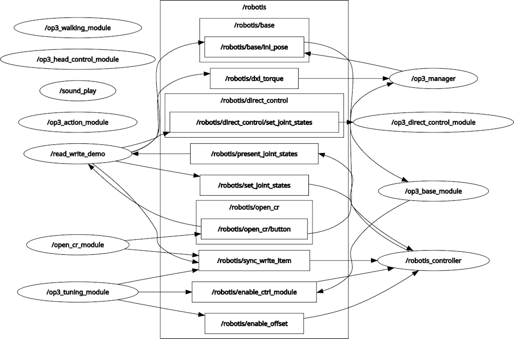
- rqt_graph
How to Operate
- Description : Buttons
From the left :modebutton,startbutton,userbutton,resetbuttonmodebutton : start read_write demo usingrobotis_controllerstartbutton : start read_write demo usingdirect_control_moduleuserbutton : torque on all jointsresetbutton : torque off all joints
Source Code
-
read_write.cpp
branch:jazzy-devel#include <rclcpp/rclcpp.hpp> #include <std_msgs/msg/string.hpp> #include <sensor_msgs/msg/joint_state.hpp> #include "robotis_controller_msgs/srv/set_module.hpp" #include "robotis_controller_msgs/msg/sync_write_item.hpp" void buttonHandlerCallback(const std_msgs::msg::String::SharedPtr msg); void jointstatesCallback(const sensor_msgs::msg::JointState::SharedPtr msg); void readyToDemo(); void setModule(const std::string& module_name); void goInitPose(); void setLED(int led); bool checkManagerRunning(std::string& manager_name); void torqueOnAll(); void torqueOff(const std::string& body_side); enum ControlModule { None = 0, DirectControlModule = 1, Framework = 2, }; const int SPIN_RATE = 30; const bool DEBUG_PRINT = false; rclcpp::Publisher<std_msgs::msg::String>::SharedPtr init_pose_pub; rclcpp::Publisher<robotis_controller_msgs::msg::SyncWriteItem>::SharedPtr sync_write_pub; rclcpp::Publisher<std_msgs::msg::String>::SharedPtr dxl_torque_pub; rclcpp::Publisher<sensor_msgs::msg::JointState>::SharedPtr write_joint_pub; rclcpp::Publisher<sensor_msgs::msg::JointState>::SharedPtr write_joint_pub2; rclcpp::Subscription<std_msgs::msg::String>::SharedPtr button_sub; rclcpp::Subscription<sensor_msgs::msg::JointState>::SharedPtr read_joint_sub; rclcpp::Client<robotis_controller_msgs::srv::SetModule>::SharedPtr set_joint_module_client; int control_module = None; bool demo_ready = false; rclcpp::Node::SharedPtr node; //node main int main(int argc, char **argv) { //init ros rclcpp::init(argc, argv); node = rclcpp::Node::make_shared("read_write_demo"); init_pose_pub = node->create_publisher<std_msgs::msg::String>("/robotis/base/ini_pose", 5); sync_write_pub = node->create_publisher<robotis_controller_msgs::msg::SyncWriteItem>("/robotis/sync_write_item", 10); dxl_torque_pub = node->create_publisher<std_msgs::msg::String>("/robotis/dxl_torque", 10); write_joint_pub = node->create_publisher<sensor_msgs::msg::JointState>("/robotis/set_joint_states", 10); write_joint_pub2 = node->create_publisher<sensor_msgs::msg::JointState>("/robotis/direct_control/set_joint_states", 10); read_joint_sub = node->create_subscription<sensor_msgs::msg::JointState>("/robotis/present_joint_states", 10, jointstatesCallback); button_sub = node->create_subscription<std_msgs::msg::String>("/robotis/open_cr/button", 10, buttonHandlerCallback); // service set_joint_module_client = node->create_client<robotis_controller_msgs::srv::SetModule>("/robotis/set_present_ctrl_modules"); rclcpp::Rate loop_rate(SPIN_RATE); // wait for starting of op3_manager std::string manager_name = "/op3_manager"; while (rclcpp::ok()) { rclcpp::sleep_for(std::chrono::seconds(1)); if (checkManagerRunning(manager_name) == true) { RCLCPP_INFO(node->get_logger(), "Succeed to connect"); break; } RCLCPP_WARN(node->get_logger(), "Waiting for op3 manager"); } readyToDemo(); //node loop while (rclcpp::ok()) { // process //execute pending callbacks rclcpp::spin_some(node); //relax to fit output rate loop_rate.sleep(); } //exit program rclcpp::shutdown(); return 0; } void buttonHandlerCallback(const std_msgs::msg::String::SharedPtr msg) { // starting demo using robotis_controller if (msg->data == "mode") { control_module = Framework; RCLCPP_INFO(node->get_logger(), "Button : mode | Framework"); readyToDemo(); } // starting demo using direct_control_module else if (msg->data == "start") { control_module = DirectControlModule; RCLCPP_INFO(node->get_logger(), "Button : start | Direct control module"); readyToDemo(); } // torque on all joints of ROBOTIS-OP3 else if (msg->data == "user") { torqueOnAll(); control_module = None; } } void jointstatesCallback(const sensor_msgs::msg::JointState::SharedPtr msg) { if(control_module == None) return; sensor_msgs::msg::JointState write_msg; write_msg.header = msg->header; for(int ix = 0; ix < msg->name.size(); ix++) { std::string joint_name = msg->name[ix]; double joint_position = msg->position[ix]; // mirror and copy joint angles from right to left if(joint_name == "r_sho_pitch") { write_msg.name.push_back("r_sho_pitch"); write_msg.position.push_back(joint_position); write_msg.name.push_back("l_sho_pitch"); write_msg.position.push_back(-joint_position); } if(joint_name == "r_sho_roll") { write_msg.name.push_back("r_sho_roll"); write_msg.position.push_back(joint_position); write_msg.name.push_back("l_sho_roll"); write_msg.position.push_back(-joint_position); } if(joint_name == "r_el") { write_msg.name.push_back("r_el"); write_msg.position.push_back(joint_position); write_msg.name.push_back("l_el"); write_msg.position.push_back(-joint_position); } } // publish a message to set the joint angles if(control_module == Framework) write_joint_pub->publish(write_msg); else if(control_module == DirectControlModule) write_joint_pub2->publish(write_msg); } void readyToDemo() { RCLCPP_INFO(node->get_logger(), "Start Read-Write Demo"); // turn off LED setLED(0x04); torqueOnAll(); RCLCPP_INFO(node->get_logger(), "Torque on All joints"); // send message for going init posture goInitPose(); RCLCPP_INFO(node->get_logger(), "Go Init pose"); // wait while ROBOTIS-OP3 goes to the init posture. rclcpp::sleep_for(std::chrono::seconds(4)); // turn on R/G/B LED [0x01 | 0x02 | 0x04] setLED(control_module); // change the module for demo if(control_module == Framework) { setModule("none"); RCLCPP_INFO(node->get_logger(), "Change module to none"); } else if(control_module == DirectControlModule) { setModule("direct_control_module"); RCLCPP_INFO(node->get_logger(), "Change module to direct_control_module"); } else { RCLCPP_ERROR(node->get_logger(), "Invalid control module : %d", control_module); return; } // torque off : right arm torqueOff("right"); RCLCPP_INFO(node->get_logger(), "Torque off"); } void goInitPose() { std_msgs::msg::String init_msg; init_msg.data = "ini_pose"; init_pose_pub->publish(init_msg); } void setLED(int led) { robotis_controller_msgs::msg::SyncWriteItem syncwrite_msg; syncwrite_msg.item_name = "LED"; syncwrite_msg.joint_name.push_back("open-cr"); syncwrite_msg.value.push_back(led); sync_write_pub->publish(syncwrite_msg); } bool checkManagerRunning(std::string& manager_name) { auto node_list = node->get_node_names(); for (const auto& node_name : node_list) { if (node_name == manager_name) return true; } RCLCPP_ERROR(node->get_logger(), "Can't find op3_manager"); return false; } void setModule(const std::string& module_name) { auto request = std::make_shared<robotis_controller_msgs::srv::SetModule::Request>(); request->module_name = module_name; if (!set_joint_module_client->wait_for_service(std::chrono::seconds(1))) { RCLCPP_ERROR(node->get_logger(), "Service not available"); return; } auto future = set_joint_module_client->async_send_request(request, [module_name](rclcpp::Client<robotis_controller_msgs::srv::SetModule>::SharedFuture result) { RCLCPP_INFO(node->get_logger(), "read_write setModule(%s) : result : %d", module_name.c_str(), result.get()->result); }); } void torqueOnAll() { std_msgs::msg::String check_msg; check_msg.data = "check"; dxl_torque_pub->publish(check_msg); } void torqueOff(const std::string& body_side) { robotis_controller_msgs::msg::SyncWriteItem syncwrite_msg; int torque_value = 0; syncwrite_msg.item_name = "torque_enable"; if(body_side == "right") { syncwrite_msg.joint_name.push_back("r_sho_pitch"); syncwrite_msg.value.push_back(torque_value); syncwrite_msg.joint_name.push_back("r_sho_roll"); syncwrite_msg.value.push_back(torque_value); syncwrite_msg.joint_name.push_back("r_el"); syncwrite_msg.value.push_back(torque_value); } else if(body_side == "left") { syncwrite_msg.joint_name.push_back("l_sho_pitch"); syncwrite_msg.value.push_back(torque_value); syncwrite_msg.joint_name.push_back("l_sho_roll"); syncwrite_msg.value.push_back(torque_value); syncwrite_msg.joint_name.push_back("l_el"); syncwrite_msg.value.push_back(torque_value); } else return; sync_write_pub->publish(syncwrite_msg); } -
Code Explanation
Themain ()function checks if the/op3_managernode is running. Otherwise, wait for it to run.// wait for starting of op3_manager std::string manager_name = "/op3_manager"; while (ros::ok()) { ros::Duration(1.0).sleep(); if (checkManagerRunning(manager_name) == true) { break; ROS_INFO_COND(DEBUG_PRINT, "Succeed to connect"); } ROS_WARN("Waiting for op3 manager"); }If
/op3_manageris running, take the initial posture for the demo and process the topic and service.readyToDemo(); //node loop while (ros::ok()) { // process //execute pending callbacks ros::spinOnce(); //relax to fit output rate loop_rate.sleep(); }When the button on the back of ROBOTIS-OP3 is pressed, it is processed by the following function.
modeandstartbuttons will start demo. If you pressuserbutton, torque of all joint will be turned on.
Before starting the demo, thereadyToDemo()function usesSyncWriteItemto turn off the right arm torque.void buttonHandlerCallback(const std_msgs::String::ConstPtr& msg) { // starting demo using robotis_controller if (msg->data == "mode") { control_module = Framework; ROS_INFO("Button : mode | Framework"); readyToDemo(); } // starting demo using direct_control_module else if (msg->data == "start") { control_module = DirectControlModule; ROS_INFO("Button : start | Direct control module"); readyToDemo(); } // torque on all joints of ROBOTIS-OP3 else if (msg->data == "user") { torqueOnAll(); control_module = None; } }If
op3_managerreceives the present value of the joint, it is processed by the following function according to demo mode.
Create a JointState message with the value of the left arm joint created by mirroring the value of the right arm joint, and pass it to theop3_manageras a topic based on each demo.void jointstatesCallback(const sensor_msgs::JointState::ConstPtr& msg) { if(control_module == None) return; sensor_msgs::JointState write_msg; write_msg.header = msg->header; for(int ix = 0; ix < msg->name.size(); ix++) { std::string joint_name = msg->name[ix]; double joint_position = msg->position[ix]; // mirror and copy joint angles from right to left if(joint_name == "r_sho_pitch") { write_msg.name.push_back("r_sho_pitch"); write_msg.position.push_back(joint_position); write_msg.name.push_back("l_sho_pitch"); write_msg.position.push_back(-joint_position); } if(joint_name == "r_sho_roll") { write_msg.name.push_back("r_sho_roll"); write_msg.position.push_back(joint_position); write_msg.name.push_back("l_sho_roll"); write_msg.position.push_back(-joint_position); } if(joint_name == "r_el") { write_msg.name.push_back("r_el"); write_msg.position.push_back(joint_position); write_msg.name.push_back("l_el"); write_msg.position.push_back(-joint_position); } } // publish a message to set the joint angles if(control_module == Framework) write_joint_pub.publish(write_msg); else if(control_module == DirectControlModule) write_joint_pub2.publish(write_msg); }
Tutorials
ROBOTIS-OP3 Bringup
Overview
This chapter explains how to run ROBOTIS-OP3. op3_bringup demo launches op3_manager.
Several modules of op3_manager are controlling ROBOTIS-OP3 and various topics and services transmit commands and report status.
The op3_manager cooperates with other programs such as op3_demo and op3_gui_demo.
Reference : op3_manager
Test environment
- Linux Mint 18.1 Serena(Base : Ubuntu Xenial)
- ROS Kinetic
Getting started
Download & Build
Reference : Installing ROBOTIS ROS Package
Stop the Linux service that run default demo
ROBOTIS-OP3 runs default demo automatically. If you would run op3_bringup demo, you have to stop the default demo service.
$ sudo service OP3-demo stop
[sudo] password for robotis: 111111
Bringup
Type below commands in the terminal window.
$ roslaunch op3_bringup op3_bringup.launch
Note that, if op3_bringup package is missing, update the package to download the missing pacakge by following the given insturction.
$ cd ~/catkin_ws/src/ROBOTIS-OP3-Demo
$ git pull
$ cd ~/catkin_ws
$ catkin_make
Execution result
When op3_bringup runs, robot moves to initial posture.
-
execution result screen
If you get an error for offset.yaml, run op3_offset_tuner(server and client) and save the offset.
-
execution result of ROBOTIS-OP3(Init pose in RVIZ)
-
It’s ready to move, now user can control ROBOTIS-OP3 using a program such as op3_gui_demo.
-
If user turn off the program, press
ctrl+cin terminal window.
op3_bringup.launch
<?xml version="1.0" ?>
<launch>
  <!-- OP3 Manager -->
  <include file="$(find op3_manager)/launch/op3_manager.launch" />

  <!-- UVC camera -->
  <node pkg="usb_cam" type="usb_cam_node" name="usb_cam_node" output="screen">
    <param name="video_device" type="string" value="/dev/video0" />
    <param name="image_width" type="int" value="1280" />
    <param name="image_height" type="int" value="720" />
    <param name="framerate " type="int" value="30" />
    <param name="camera_frame_id" type="string" value="cam_link" />
    <param name="camera_name" type="string" value="camera" />
  </node>
</launch>
- op3_manager : framework to control of ROBOTIS-OP3
- Robot file :
op3_manager/config/OP3.robot - Joint initialize file :
op3_manager/config/dxl_init_OP3.yaml - Offset file :
op3_manager/config/offset.yaml
- Robot file :
- usb_cam_node : package for usb camera of ROBOTIS-OP3
Visualization
Type below commands in the terminal window for visualization.
$ roslaunch op3_bringup op3_bringup_visualization.launch
-
rviz screen
-
TF Tree
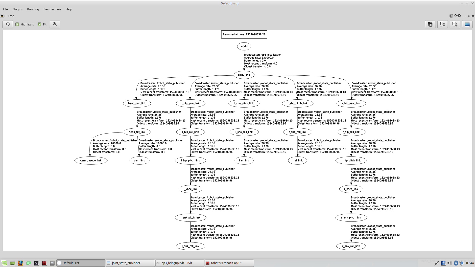
If you want to see the TF Tree, follow the below instruction.
- Launch
rqt$ rqt - select
Plugins -> Visualization -> TF Tree
- Launch
-
op3_bringup_visualization.launch
<?xml version="1.0" ?>
<launch>
  <param name="robot_description" command="$(find xacro)/xacro.py '$(find op3_description)/urdf/robotis_op3.urdf.xacro'"/>

  <!-- Send fake joint values and monitoring present joint angle -->
  <node pkg="joint_state_publisher" type="joint_state_publisher" name="joint_state_publisher">
    <param name="use_gui" value="TRUE"/>
    <rosparam param="/source_list">[/robotis/present_joint_states]</rosparam>
  </node>

  <!-- Combine joint values -->
  <node pkg="robot_state_publisher" type="state_publisher" name="robot_state_publisher">
    <remap from="/joint_states" to="/robotis/present_joint_states" />
  </node>

  <!-- Show in Rviz   -->
  <node pkg="rviz" type="rviz" name="rviz" args="-d $(find op3_bringup)/rviz/op3_bringup.rviz"/>
</launch>
- parameter
- robot_description : robot model for TF and visualization in rviz
- joint_state_publisher : visualization of joint value of ROBOTIS-OP3
- robot_state_publisher : making TF message for robot model
- rviz : visualization tool
Description
This section explains configuration files used in op3_manager(within op3_bringup.launch).
Robot file(.robot)
Information of the robot to operate.
Control frequency, communication interface, baud rate, available devices and their properties are defined.
-
Default path of Robot File :
op3_manager/config/OP3.robot -
Contents
[ control info ]
control_cycle = 8   # milliseconds

[ port info ]
# PORT NAME  | BAUDRATE  | DEFAULT JOINT
/dev/U2D2    | 2000000   | r_sho_pitch

[ device info ]
# TYPE    | PORT NAME    | ID  | MODEL          | PROTOCOL | DEV NAME       | BULK READ ITEMS
dynamixel | /dev/U2D2    | 1   | XM-430         | 2.0      | r_sho_pitch    | present_position
dynamixel | /dev/U2D2    | 2   | XM-430         | 2.0      | l_sho_pitch    | present_position
dynamixel | /dev/U2D2    | 3   | XM-430         | 2.0      | r_sho_roll     | present_position
dynamixel | /dev/U2D2    | 4   | XM-430         | 2.0      | l_sho_roll     | present_position
dynamixel | /dev/U2D2    | 5   | XM-430         | 2.0      | r_el           | present_position
dynamixel | /dev/U2D2    | 6   | XM-430         | 2.0      | l_el           | present_position
dynamixel | /dev/U2D2    | 7   | XM-430         | 2.0      | r_hip_yaw      | present_position
dynamixel | /dev/U2D2    | 8   | XM-430         | 2.0      | l_hip_yaw      | present_position
dynamixel | /dev/U2D2    | 9   | XM-430         | 2.0      | r_hip_roll     | present_position
dynamixel | /dev/U2D2    | 10  | XM-430         | 2.0      | l_hip_roll     | present_position
dynamixel | /dev/U2D2    | 11  | XM-430         | 2.0      | r_hip_pitch    | present_position
dynamixel | /dev/U2D2    | 12  | XM-430         | 2.0      | l_hip_pitch    | present_position
dynamixel | /dev/U2D2    | 13  | XM-430         | 2.0      | r_knee         | present_position
dynamixel | /dev/U2D2    | 14  | XM-430         | 2.0      | l_knee         | present_position
dynamixel | /dev/U2D2    | 15  | XM-430         | 2.0      | r_ank_pitch    | present_position
dynamixel | /dev/U2D2    | 16  | XM-430         | 2.0      | l_ank_pitch    | present_position
dynamixel | /dev/U2D2    | 17  | XM-430         | 2.0      | r_ank_roll     | present_position
dynamixel | /dev/U2D2    | 18  | XM-430         | 2.0      | l_ank_roll     | present_position
dynamixel | /dev/U2D2    | 19  | XM-430         | 2.0      | head_pan       | present_position
dynamixel | /dev/U2D2    | 20  | XM-430         | 2.0      | head_tilt      | present_position
sensor    | /dev/U2D2    | 200 | OPEN-CR        | 2.0      | open-cr        | button, present_voltage, gyro_x, gyro_y, gyro_z, acc_x, acc_y, acc_z, roll, pitch, yaw
Reference : Robot Information file(.robot)
Joint Initialize File (.yaml)
Set initialization values for properties of DYNAMIXEL or sensor.
-
Default path of Initialization file :
op3_manager/config/dxl_init_OP3.yaml -
Contents
r_sho_pitch :   # XM-430
   return_delay_time        : 1    # item name : value
   min_position_limit       : 0
   max_position_limit       : 4,095

r_sho_pitch :   # XM-430
   return_delay_time        : 1    # item name : value
   min_position_limit       : 0
   max_position_limit       : 4,095

...
Reference : Joint initialize file(.yaml)
Offset file(.yaml)
If the robot is mechanically distorted due to assembly tolerance and other reasons, adjusting offset can help to correct the error.
Offset file contains offset angles of each joint(radian) to correct distortion and initial posture joint angles for Offset Tuner.
-
Default path of Offset file :
op3_manager/config/offset.yaml -
Contents
offset:
  head_pan: 0
  head_tilt: 0
  l_ank_pitch: 0.0174532925199433
  l_ank_roll: 0
  l_el: 0
  l_hip_pitch: 0.01221730476396031
  l_hip_roll: -0.01570796326794897
  l_hip_yaw: 0.004363323129985824
  l_knee: 0.006981317007977318
  l_sho_pitch: 0
  l_sho_roll: 0
  r_ank_pitch: 0.008726646259971646
  r_ank_roll: 0
  r_el: 0
  r_hip_pitch: 0.01658062789394613
  r_hip_roll: 0.0148352986419518
  r_hip_yaw: 0.008726646259971646
  r_knee: 0.008726646259971646
  r_sho_pitch: 0
  r_sho_roll: 0
init_pose_for_offset_tuner:
  head_pan: 0
  head_tilt: 0
  l_ank_pitch: 0
  l_ank_roll: 0
  l_el: 0
  l_hip_pitch: 0
  l_hip_roll: 0
  l_hip_yaw: 0
  l_knee: 0
  l_sho_pitch: 0
  l_sho_roll: 0
  r_ank_pitch: 0
  r_ank_roll: 0
  r_el: 0
  r_hip_pitch: 0
  r_hip_roll: 0
  r_hip_yaw: 0
  r_knee: 0
  r_sho_pitch: 0
  r_sho_roll: 0
Reference : How to use offset tuner
How to execute Default Demo
Overview
This chapter explains how to play basic demonstrations of OP3. There are three available demos; playing soccer, vision and sequence of various actions.
Reference : op3_demo
Getting started
Download & Build
Reference : Installing ROBOTIS ROS Package
Run
-
Auto Start
ROBOTIS-OP3 begins to play demo when startup. -
Manual Start
Connect to ROBOTIS-OP3 and open the terminal window. Acquire the root permission and execute the launch file.
Enter the following commands in the terminal.
(password : 111111)
The demo launch file executesop3_demoandop3_manager.
  $ sudo bash
  [sudo] password for robotis: 111111
  # roslaunch op3_demo demo.launch
Execution result
DYNAMIXEL of ROBOTIS-OP3 will be powered and take the initial posture.
Description
Button Functions
From the left, each button is assigned for Mode, Start, User and Reset.
- Mode button
- short press : In Ready Mode, mode button switches to the next demo(soccer > vision > action)
- long press : While demo is running, press and hold the mode button to switch to Ready Mode.
- Start button
- short press : Play selected demo from Ready Mode. If demo is running, start button will pause or resume demo.
-
User button
- Reset button
- Reset button will cut off the power to all DYNAMIXEL.
Soccer Demo
-
How to play Press the mode button once from demonstration ready mode to switch to autonomous soccer mode, then play soccer demo by pressing the start button.
(ROBOTIS-OP3 will announce “Autonomous soccer mode” and red LED in the back will be lit.)
When the demo begins, ROBOTIS-OP3 will announce “Start soccer demonstration” and stand up to search for a ball.
If desired ball is detected, walk close to the ball and kick it. - Setting Walking Parameters
Walking motion imports parameters saved in the
op3_walking_moduleinop3_manager. Default parameters can be configured by using walking tuner in theop3_gui_demo.Reference : How to use walking tuner
- Return to Demonstration Ready Mode
Pressing and holding the mode button for 3 seconds will make ROBOTIS-OP3 to take the initial posture and return to Demonstration ready mode.
Vision Demo
- How to Play
Press the mode button twice from demonstration ready mode to switch to vision processing mode, then play vision demo by pressing the start button.
(ROBOTIS-OP3 will announce “Vision processing mode” and green LED in the back will be lit.)
When the demo begins, ROBOTIS-OP3 will announce “Start vision processing demonstration” and stand up to search for a face.
If a face is detected, RGB-LED on the chest and back turns into white color and OP3’s head will follow the detected face.Reference : Face Tracker - ROS Package
- Return to Demonstration Ready Mode
Pressing and holding the mode button for 3 seconds will make ROBOTIS-OP3 to take the initial posture and return to Demonstration ready mode.
Action Demo
-
How to Play Press the mode button thrice from demonstration ready mode to switch to interactive motion mode, then play action demo by pressing the start button. (ROBOTIS-OP3 will announce “Interactive motion mode” and blue LED in the back will be lit.)
When the demo begins, ROBOTIS-OP3 will start playing predefined action sequence along with audio.
action_script.yamlcontains motion and audio bundles. action_script.yamlfile description- File path :
/op3_demo/script/action_script.yaml -
Contents
# combination action page number and mp3 file path action_and_sound: 4 : "/home/robotis/catkin_ws/src/ROBOTIS-OP3/ROBOTIS-OP3-Demo/op3_demo/Data/mp3/Thank you.mp3" 41: "/home/robotis/catkin_ws/src/ROBOTIS-OP3/ROBOTIS-OP3-Demo/op3_demo/Data/mp3/Introduction.mp3" 24: "/home/robotis/catkin_ws/src/ROBOTIS-OP3/ROBOTIS-OP3-Demo/op3_demo/Data/mp3/Wow.mp3" 23: "/home/robotis/catkin_ws/src/ROBOTIS-OP3/ROBOTIS-OP3-Demo/op3_demo/Data/mp3/Yes go.mp3" 15: "/home/robotis/catkin_ws/src/ROBOTIS-OP3/ROBOTIS-OP3-Demo/op3_demo/Data/mp3/Sit down.mp3" 1: "/home/robotis/catkin_ws/src/ROBOTIS-OP3/ROBOTIS-OP3-Demo/op3_demo/Data/mp3/Stand up.mp3" 54: "/home/robotis/catkin_ws/src/ROBOTIS-OP3/ROBOTIS-OP3-Demo/op3_demo/Data/mp3/Clap please.mp3" 27: "/home/robotis/catkin_ws/src/ROBOTIS-OP3/ROBOTIS-OP3-Demo/op3_demo/Data/mp3/Oops.mp3" 38: "/home/robotis/catkin_ws/src/ROBOTIS-OP3/ROBOTIS-OP3-Demo/op3_demo/Data/mp3/Bye bye.mp3" # play list default: [4, 41, 24, 23, 15, 1, 54, 27, 38] - action_and_sound : Combined information of page number of action file and mp3 file path to play with
action number : mp3 file path - default : Play list of action and sound in the interactive motion mode
- File path :
- Return to Demonstration Ready Mode
Pressing and holding the mode button for 3 seconds will make ROBOTIS-OP3 to take the initial posture and return to Demonstration ready mode.
How to execute GUI program
Reference : op3_gui_demo
Run the program
There are three options to run the GUI program.
- Connect input devices and display device directly to ROBOTIS-OP3 and run the GUI program on the robot.
- Use VNC from a remote PC to obtain control over the OP3 SBC(Intel NUC) and initiate the GUI program remotely.
-
Run the GUI program on a remote PC in the same ROS network with ROBOTIS-OP3.
Open the terminal window and enter the following command.
op3_managershould be running before executing GUI demo program.$ roslaunch op3_gui_demo op3_demo.launchReference : How to run op3_manager
- Execution result
How to take the initial pose of ROBOTIS-OP3
Clicking the button surrounded by the red dashed rectangle will let the base_module control each joint of ROBOTIS-OP3 and take the initial posture.
How to set the Module
- Follow the below procedure to configure modules that control corresponding joint of ROBOTIS-OP3.
-
Click the module button to configure.
-none
-head_control_module
-action_module
-walking_module -
Confirm from the joint status table below the module buttons that corresponding joints are set correctly.
-
-
Get Modebutton will report which module is assigned for each joint.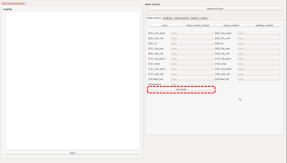
How to use walking tuner
Overview
This chapter explains how to configure walking parameters and test them with ROBOTIS-OP3.
Basic demo uses saved walking parameters.
Description
Setting Module
Activate walking_module on the lower body part of ROBOTIS-OP3 for walking test.
Confirm that the joints used for walking are set as walking_module, then move to Walking tab.
(When the walking module is activated, ROBOTIS-OP3 will take the initial posture for walking.)
Start / Stop Walking
startbutton : Initiate walkingstopbutton : Stop walking. When stopped, walking related parameters will be reset.
Apply Parameters
Refreshbutton : Acquire all parameter currently applied onwalking_module.Savebutton : Save all parameter currently applied onwalking_moduleas default parameter and use it for other program such asop3_demo.Applybutton : Apply modified parameters from the GUI towalking_module.
How to play the motions
Overview
This chapter explains how to play predefined actions.
The action_module controls each joint of ROBOTIS-OP3.
Reference : op3_action_module
Description
How to play
- Set the module : Press the
action_modulebutton. -
Select
Motiontab of the gui demo program.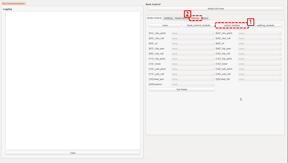
-
Click the action button to play
Creating and editing actions for action_module
Reference : How to create the motions
How to control the head joints
Overview
This chapter explains how to control the head joint of ROBOTIS-OP3.
Operator can get different camera view angle by controlling head joints.
Reference : op3_head_control_module
Head Joint Control
- Setting the Module : Click
head_control_modulebutton -
Select
Head Controltab of the gui demo program.
- Change the value for the specific joint.
- Use the slide bar to control the head joint.
- Enter desired values in the text box to control the head joint.
- Bring the head joint to center position.
How to control upgraded walking(online walking)
Overview
This page explains how to control upgraded walking(online walking).
Reference 1 : Introduction to Humanoid Robotics
Reference 2 : op3_online_walking_module
Description
How to
- Preparation : Set the module and move to the tab
- Setting the module : Click
online_walking_modulebutton - Select
Online Walkingtab of the gui demo program.
- Setting the module : Click
- Controlling walking of ROBOTIS-OP3
- Go to initial pose : click
Go to Initial Posebutton - Balance On
- Set the walking parameters
- Send a walking command to
op3_manager
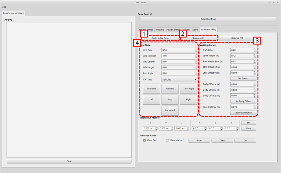
- Walking parameters
- DSP ratio : double support phase ratio
- LIPM Height : linear inverted pendulum height
- Foot Height Max : maximum value of foot height
- ZMP Offset x : ZMP offset for x-direction
- ZMP Offset y : ZMP offset for y-direction(The larger the value, the outer the zmp.)
- Body Offset : desired body offset
- Foot Distance : desired foot distance between left and right foot`
- Go to initial pose : click
Online walking using footstep planner
Reference : Online walking using footstep planner
How to use offset tuner
Overview
deprecated
This chapter has been merged into How to use tuner client
Reference : op3_offset_tuner_server
Reference : op3_offset_tuner_client
How to use tuner client
Overview
this chapter explains how to adjust kinematic offset and position gain of ROBOTIS-OP3. In the past, we were able to adjust the offset by using op3_offset_server and op3_offset_client. Now we can set both offset and gain using new op3_tuning_module and op3_tuner_client. we made an op3_tuning_module and used it with op3_manager, so you do not need to run the server for using just to tune the offset.
Reference : op3_tuning_module
Reference : op3_tuner_client
- Before
- After
Run Tuner Program
How to launch programs
Launching op3_manager and op3_tuner_client program separately
Tuner is consisted of op3_manager and client program so that other PC in the same ROS network can tune offsets and gains.
Execute the op3_manager first.
(Other programs such as op3_action_editor and op3_walking_tuner should be terminated to run the op3_manager).
$ roslaunch op3_manager op3_manager.launch
After starting the op3_manager, execute client GUI program from the identical PC or any PCs in the same ROS network.
$ roslaunch op3_tuner_client op3_tuner_client.launch
Launching op3_manager and op3_tuner_client program at once
Enter the following commands in the terminal window.
(Other programs such as op3_action_editor and op3_walking_tuner should be terminated to run the offset tuner.)
$ roslaunch op3_tuner_client op3_tuner.launch
Configuration Files
op3_manager configuration files
- config/
OP3.robot: Description of ROBOTIS-OP3 is saved - config/
dxl_init_OP3.yaml: DYNAMIXEL configurations included gains are saved and used for joint initialization
op3_tuning_module configuration files
- data/
offset.yaml: Offset data is saved -
data/
tune_pose.yaml: offset adjusting posture information and gain tuning posture information are saved- init_pose - move_time - target_pose - joint_name : angle(degree) - ... - tune_pose_01 - move_time : [time, time, ...] - target_pose : [pose_name, pose_name, ...] - tune_pose_02 - move_time : [time, time, ...] - target_pose : [pose_name, pose_name, ...] - tune_pose_03 - move_time : [time, time, ...] - target_pose : [pose_name, pose_name, ...] - tune_pose_04 - move_time : [time, time, ...] - target_pose : [pose_name, pose_name, ...] - pose_data - pose_name - joint_name : angle(degree) - ...
op3_tuner_client configuration file
- config/
joint_data.yaml: GUI menu configuration file
How to use tuner client GUI program
How to tune the offset
- go
Initial Pose - Select tab of
Kinematics Group - Click the
RefreshButton for getting current states of joints - tune the offset of joints
- Click the
Save Offsetbutton for saving to file.
How to tune the gain
- go
Initial Pose - Select tab of
Kinematics Group - Click the
RefreshButton for getting current states of joints - change the pose and tune the gain of joints for watching the graph of the joint
(If you want to tune other joint, delete topics and add topics that you want to tune) - Click the
Save Gainbutton for saving to file.
Reference : Order of the joint name in the topic(
/robotis/goal_joint_states)
  0 : haed_pan
  1 : haed_tilt
  2 : l_ank_pitch
  3 : l_ank_roll
  4 : l_el
  5 : l_hip_pitch
  6 : l_hip_roll
  7 : l_hip_yaw
  8 : l_knee
  9 : l_sho_pitch
  10 : l_sho_roll
  11 : r_ank_pitch
  12 : r_ank_roll
  13 : r_el
  14 : r_hip_pitch
  15 : r_hip_roll
  16 : r_hip_yaw
  17 : r_knee
  18 : r_sho_pitch
  19 : r_sho_roll
If you want to check in your hand, type like the belows
$ rostopic echo /robotis/goal_joint_states -n 1
How to create the motions
Overview
ROBOTIS-OP3 Action Editor Node.
This chapter explains how to create and edit action file used in the op3_action_module of ROBOTIS-OP3.
Action File
The action file contains ROBOTIS-OP3’s poses and time data. The current position describes positions of DYNAMIXEL which converted from actual DYNAMIXEL resolution to 4,095 resolution. The action file is written as binary file so users can read its contents with op3_action_editor. ROBOTIS currently provides a default action file with source code. It is located in “op3_action_module/data” directory.
The action file contains 256 pages. Each page can store up to 7 stages (or steps) of action data. The default action file does not use all pages and user can add own actions by writing them on the empty page.
Getting started
Download & Build
Reference : Installing ROBOTIS ROS Package
Run
Execute the launch file.
op3_action_editor has a direct control over ROBOTIS-OP3, therefore other control programs such as op3_manager, op3_offset_tuner and op3_walking_tuner should not be running.
Before executing the op3_action_editor launch file, other programs should be terminated.
$ roslaunch op3_action_editor op3_action_editor.launch
UI
- Page number: Page number is the listed page number. If user wants to create a new action poses, user can use any empty page.
- Page title: ROBOTIS recommends user to use a page title when creating a new action on an empty page.
- Current position: The current position describes position of DYNAMIXEL which converted from actual DYNAMIXEL resolution to 4,095 resolution. This data is represented by STP7 in op3_action_editor. Sometimes the position may be read as —- in op3_action_editor. This means position of DYNAMIXEL has not been read (or torque is off).
If user turns DYNAMIXEL off, current position cannot be read until turn it back on.
User can turn off the torque of specific DYNAMIXEL. This is very convenient when acquiring position values directly from DYNAMIXEL for a new robot posture instead of calculating those values. To do that, turn off the torque of desired DYNAMIXEL, then make a posture and hold the robot joint by hand until turn the torque back on. The robot will be remaining at current posture and user can read position values of corresponding DYNAMIXEL. - Steps or stages: Each page can store up to 7 steps, from STP0 to STP6. However, some actions may be required more than 7 stages to perform completely. This can be resolved by simply using multiple pages and link them with Next
- Next: Next indicates whether to continue action on a different page. To continue actions, just list the page number where the action is to be continued. Number 0 indicates that action does not continue onto another page (default value). Linking page does not have to have the numerical order.
- Play Count: Play Count is the number of times the action of the page is to be played.
- Exit: There might be some cases when an action has to be stopped. In these cases, the robot may be in unstable position. Exit is much like “Next”, so “Exit” should be linked to a page where ROBOTIS-OP3 can return to a stable pose. If “Exit” is 0, it means that there is no linked exit page (default value).
Tip: When calling an action requires multiple pages, ROBOTIS strongly suggests user to call the action from the starting page. For example, clap starts at page 7 and ends at page 8. This means you should call page 7 when calling clap. Calling the page 8 may cause unexpected behavior of the robot. - STP7: “STP7” column is the current position of DYNAMIXEL which converted to 4,095 resolution from its original resolution. “—-“ means that torque has been released.
- PauseTime: “PauseTime” is the pause duration period for motion playback for step STP[x].
- Time(x 8msec) : “Time” is the time period for ROBOTIS-OP3 to complete step STP[x]. Each time unit account for 8ms of time.
It is strongly advised that when user tests user’s own newly-created or edited actions, there should be small incremental changes in position, speed/time, and pause values for the sake of ROBOTIS-OP3’s stability.
The Contents of The Default Action File
The below table shows the contents of the default action file.
| page number | page title | brief description of page | number of pages |
|---|---|---|---|
| 1 | walki_init | initial standing pose | 1 |
| 2 | hello | greeting | 1 |
| 3 | thank_you | Thank you | 1 |
| 4 | yes | yes | 1 |
| 5 | no | no | 1 |
| 6 | fighting | fighting | 1 |
| 7 | clap | clap | 2 |
| 9 | S_H_RE | ready for shaking hands | 1 |
| 10 | S_H | shaking hands | 1 |
| 11 | S_H_END | move to initialpose fram ready pose for shaking hands | 1 |
| 12 | scanning | looking around | 1 |
| 13 | ceremony | ceremony | 1 |
Basic Command of Action Editor
After typing “help”, the commend list will appear as shown below.
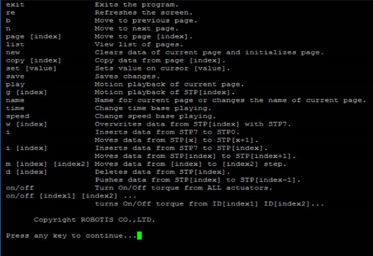
- exit: exits the program.
- re: refreshes the screen.
- b: moves to the previous page.
- n: moves to the next page.
- page [index]: moves to the [index] page. For example typing page 5 outputs data from page 5 on screen.
- list: outputs a list of pages.
- new: initializes current page by clearing all actuator position data.
- copy [index]: copies data from page [index] to current page. For example if you are on page 5 and want to copy page 9 then type copy 9.
- set [value]: sets position value on chosen actuator. For example If you want ID19 (head pan) to have a value of 512 then using the keyboard’s directional keys place the cursor on ID19 and type set 512.
- save: saves any changes you’ve made. the saved motion file (motion_4096.bin can be found at “op3_action_module/data”)
- play: plays motion(s) of current page.
- name: changes the name of the current page. You can view the name of the page at the top right portion of the screen. For example, page 2 is titled hello; to change the name type name and press the “ENTER” key. “name:” will appear at the bottom of the screen. Input the desired name for the page, good for instance, and press the “ENTER” key again.
- i: inserts data from STP7 to STP0. Moves data from STP[x] to STP[x + 1] if any.
- i [index]: inserts data from STP7 to STP[index]. Moves data from STP[index] to STP[index + 1] if any.
- m [index] [index2]: moves data from [index2] to [index].
- d [index]: deletes data from STP[index]. Moves data from STP[index] to STP[index - 1].
- on/off: turns on/off torque from all DYNAMIXEL.
- on/off [index1] [index2] [index3] … : turns torque on/off from ID[index1] ID[index2] ID[index3]. For example off 20 releases torque from ID20. Notice that STP7 for ID20 will read [—-]. Typing on 20 turns torque from ID20 on again and the screen outputs the current position data of ID20.
Example Action editing with op3_action_editor
- Run the op3_action_editor
-
Find the page where the “walking_init page” is by typing “list”
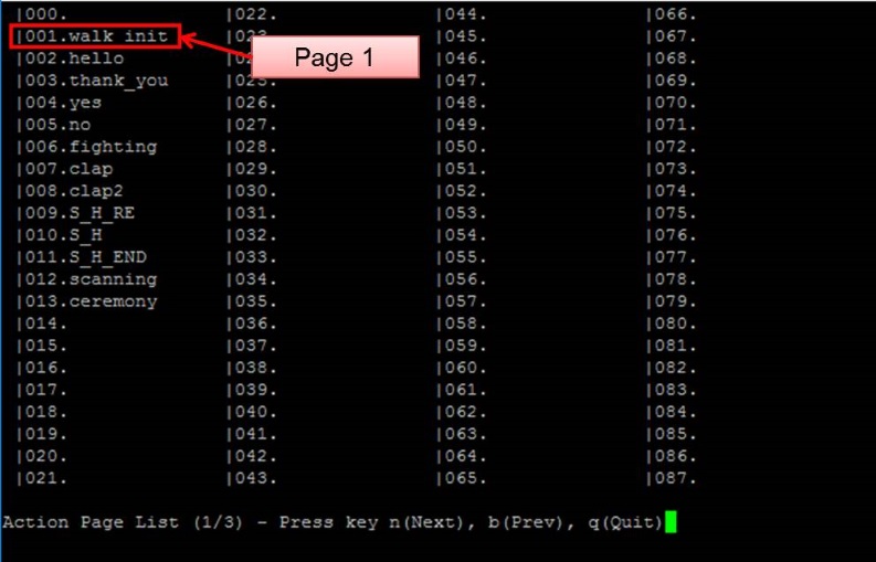
-
Exit the list and go to any blank page by typing “page [x]”(for example, page 15).
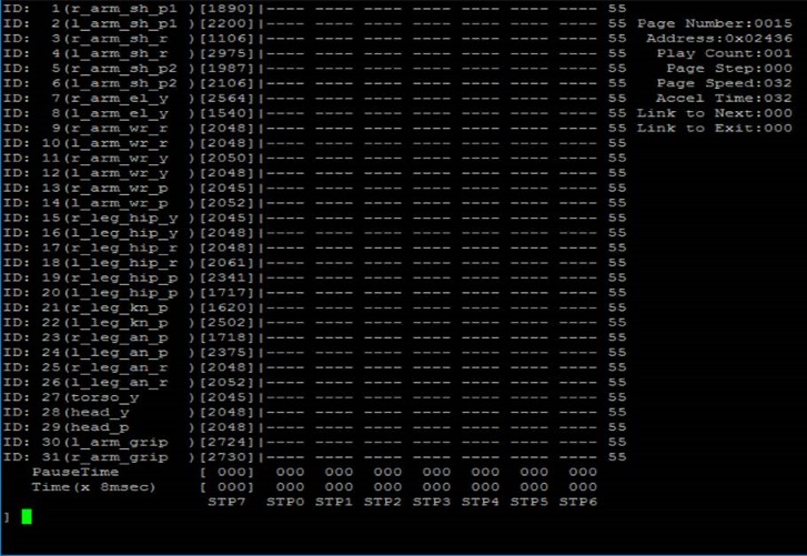
-
And copy the page 1 to page [x].
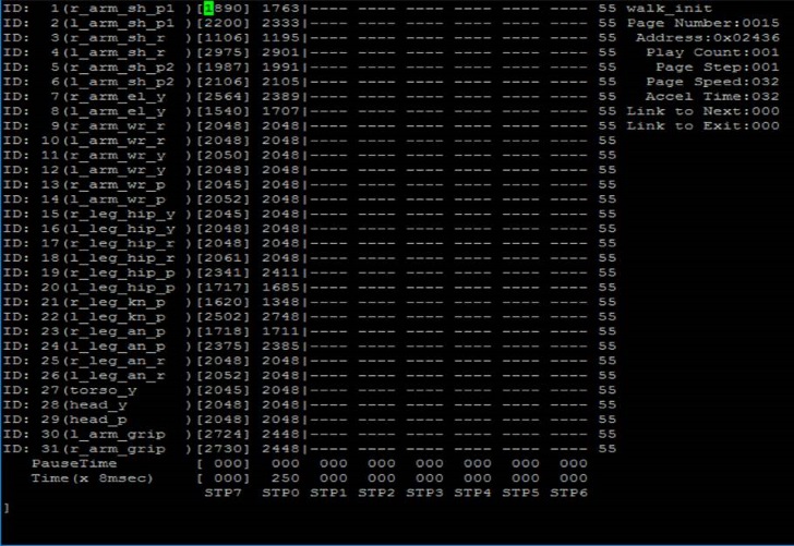
- Go to “walking_init” pose by typing “play”
-
Turn off the torque of ID 2, 4 and 8 by typing “off 2 4 8”
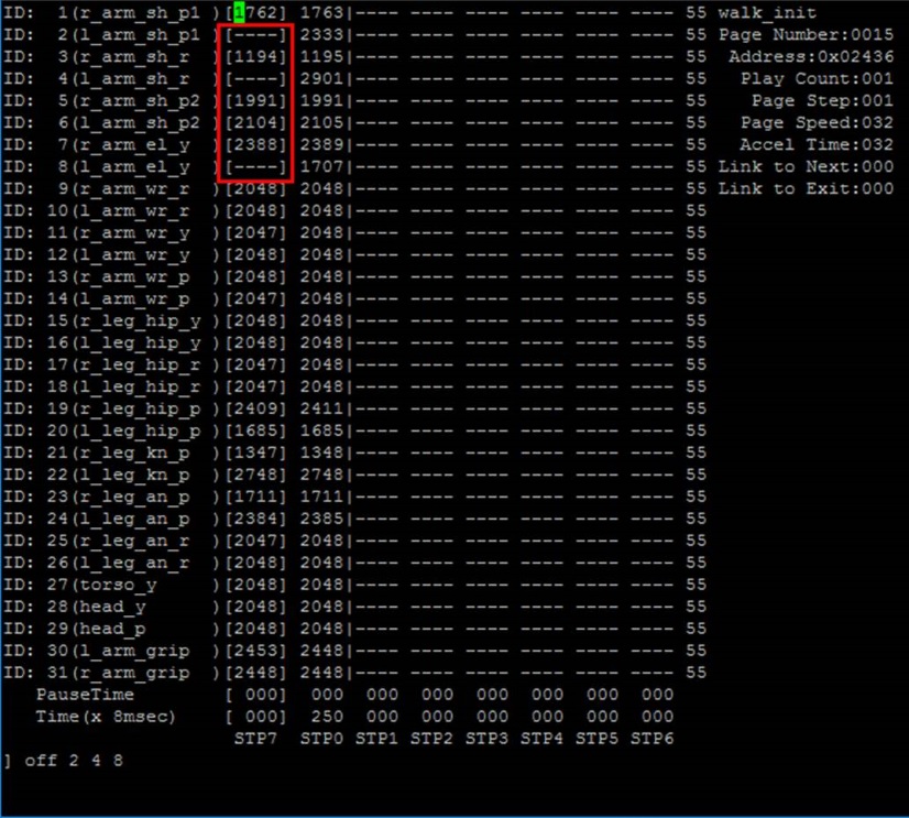
-
After getting the desired pose turn torque on again by simple typing on. And insert the pose to step 1 by typing “i 1”
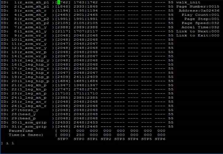
-
Edit “Pause Time”, “Time” of STP1 and “Page Step” as shown below.
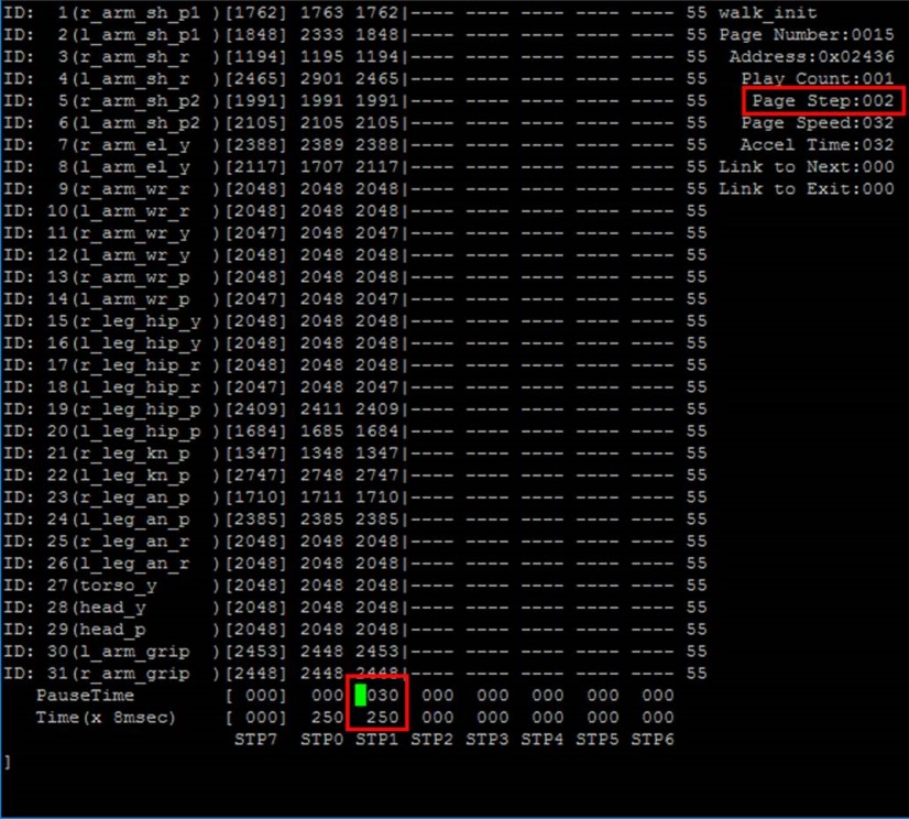
- Type “play” and check the ROBOTIS-OP3’s action
How to use ball detector
Overview
This chapter explains how to calibrate the ball_detector_node to find a ball. The ball_detector_node detects a ball by the designated color and Hough Circle Transform.
Getting started
Run the program
$ roslaunch ball_detector ball_detector_from_usb_cam.launch
or
$ roslaunch op3_demo demo.launch
How to change the parameters
- Dynamic Reconfigure and Image View
-
run the
rqt$ rqt -
Open
Dynamic Reconfigure
SelectPlugins -> Configuration -> Dynamic Reconfigure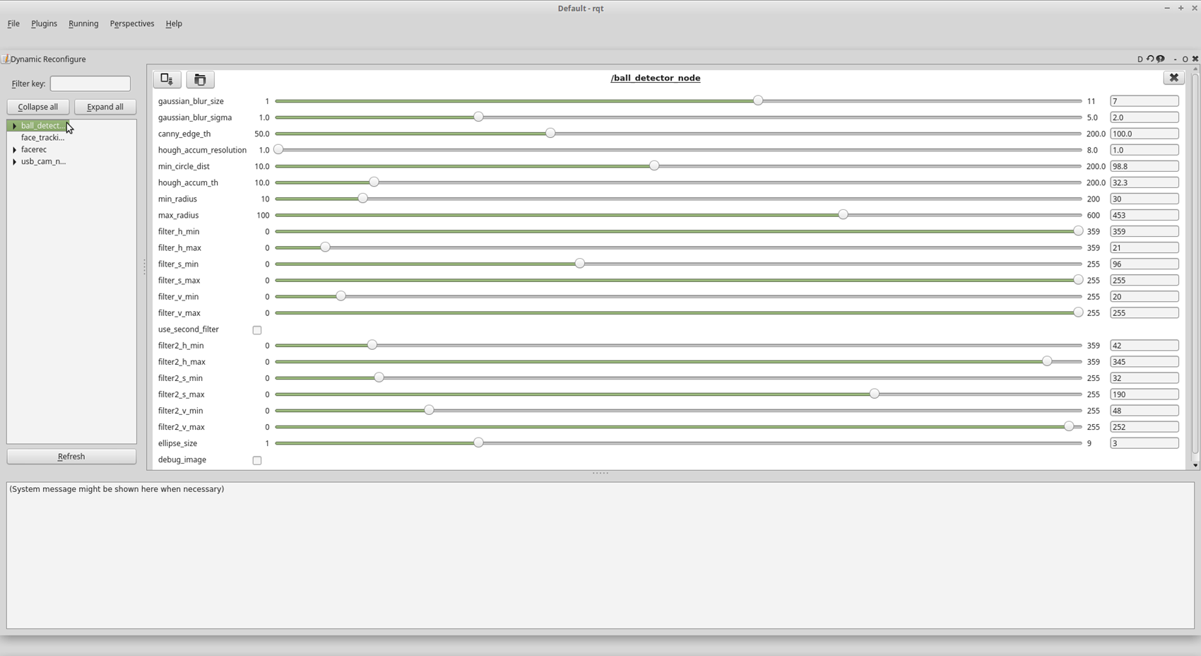
-
Open
Image View
SelectPlugins -> Visualization -> Image View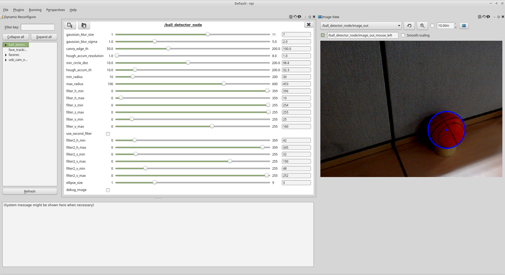
-
-
Parameters
The description for each parameter will pop up when hovering the mouse cursor over each parameter.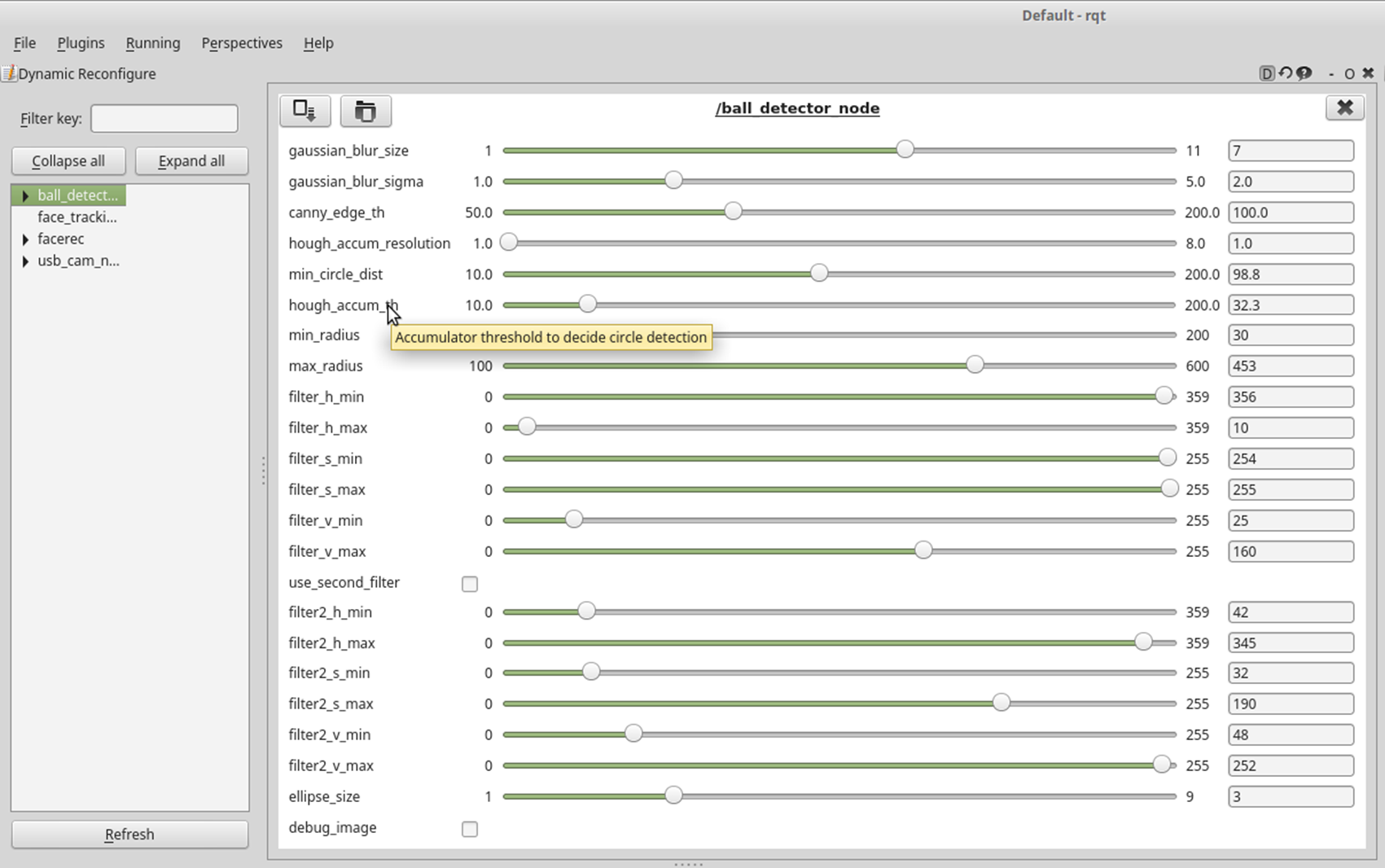
- gaussian_blur_size: Size of Gaussian Blur Kernel (odd value)
- gaussian_blur_sigma: Std deviation of Gaussian Blur
- canny_edge_th: Threshold of the edge detector
- hough_accum_resolution: Resolution of the Hough accumulator, in terms of inverse ratio of image resolution
- min_circle_dist: Minimum distance between circles
- hough_accum_th: Accumulator threshold to decide center detection
- min_radius: Minimum circle radius allowed, pixels. (if unknown, put 0 for a detault.)
- max_radius: Maximum circle radius allowed, pixels. (if unknown, put 0 for a detault.)
- filter_h_min: Minimum threshold of H filter
- filter_h_max: Maximum threshold of H filter
- filter_s_min: Minimum threshold of S filter
- filter_s_max: Maximum threshold of S filter
- filter_v_min: Minimum threshold of V filter
- filter_v_max: Maximum threshold of V filter
- use_second_filter: Use second filter
- filter2_h_min: Minimum threshold of H filter
- filter2_h_max: Maximum threshold of H filter
- filter2_s_min: Minimum threshold of S filter
- filter2_s_max: Maximum threshold of S filter
- filter2_v_min: Minimum threshold of V filter
- filter2_v_max: Maximum threshold of V filter
- ellipse_size: Ellipse size
- debug_image: Show filtered image to debug
- Description
-
How the ball_detector_node works
ball_detector_node filters the HSV value first, then detect the ball withHoughCircles -
How to calibrate
-
Set H(hue) value (color value) first with full range of S and V. Then set the range of S(saturation) and V(value) to remove the noise.
Hueis measured by degrees within the cylindrically represented color system. Therefore, the value 360 can be represented as 0, and the minimum value can have a bigger number than the maximum value. (ex : min - 350 / max - 10 [Red area]) -
If you check the
use_second_filteryou can get an image which is detected with two HSV variations.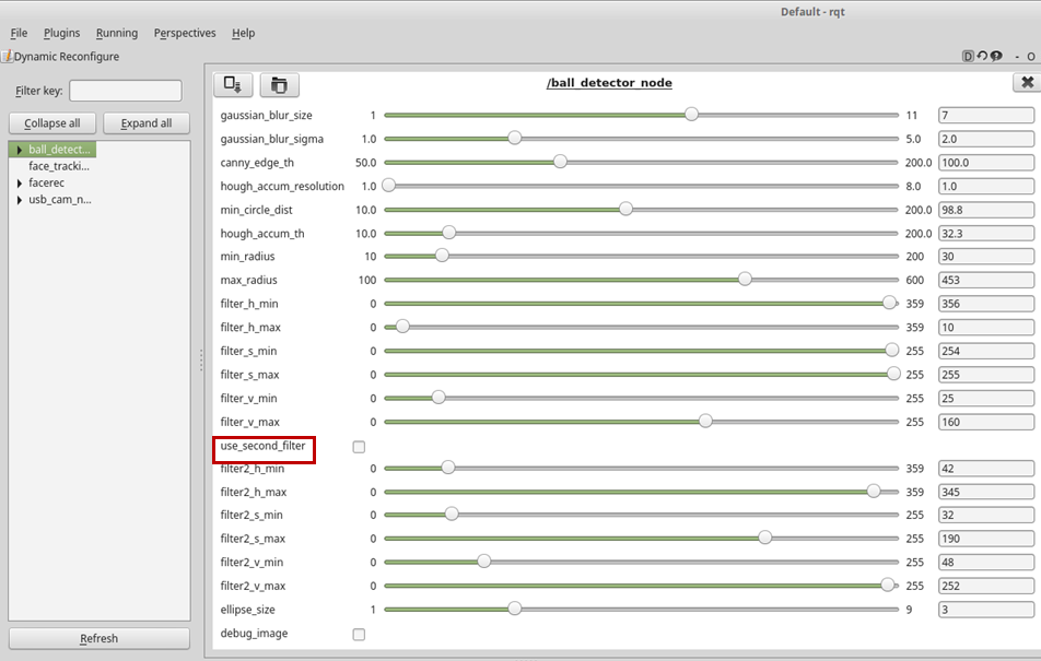
-
If you check the
debug_imageyou can check the HSV filtered, binary image.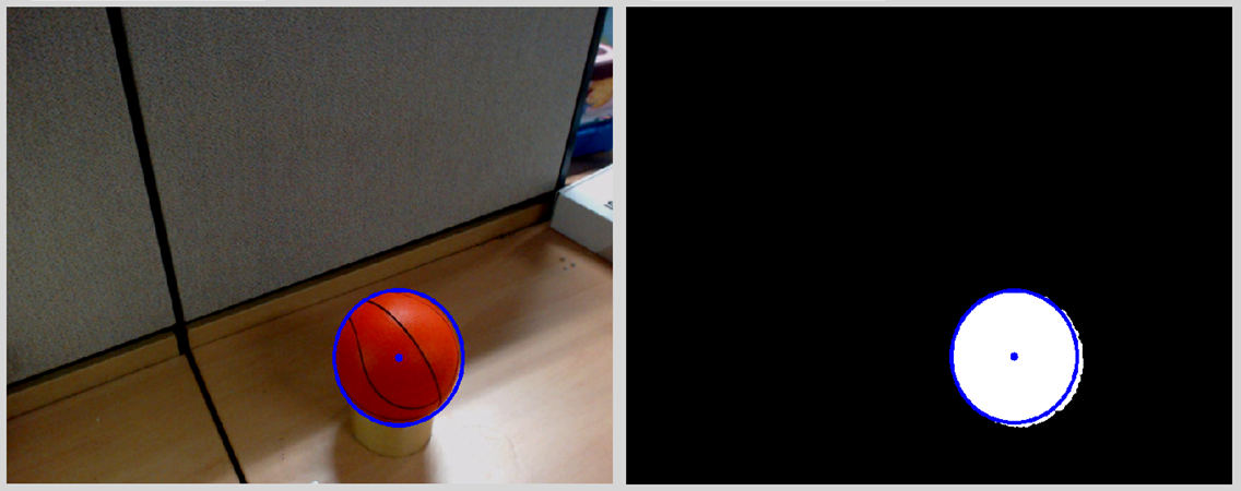
-
After you set the HSV range, you could calibrate the threshold value to detect the edge better.
-
-
How to control upgraded walking using footstep planner
Overview
This chapter explains upgraded walking and footstep planner.
Reference : op3_how_to_control_upgraded_walking
Getting started
Installation
-
humanoid_navigation for footstep planner
follow link and install the packages -
-
Download source
$ cd ~/catkin_ws/src $ git clone https://github.com/ROBOTIS-GIT/ROBOTIS-OP3-Tools.git -
Build source
$ cd ~/catkin_ws
$ catkin_make
-
Run the program
-
op3_manager
$ roslaunch op3_manager op3_manager.launch -
op3_gui_demo and footstep planner
$ roslaunch op3_gui_demo op3_demo_walking.launch -
rviz for upgraded walking with footstep planner. If user want to launch a rviz in ROBOTIS-OP3, a monitor is connected to ROBOTIS-OP3.
$ roslaunch op3_description op3_walking.launch
Walking with footstep planner
Preparation : Set the module and move to the tab
- Setting the module : Click
online_walking_modulebutton -
Select
Online Walkingtab of the gui demo program.
Controlling walking of ROBOTIS-OP3
- Go to initial pose : click
Go to Initial Posebutton - Balance On
-
Set the walking parameters
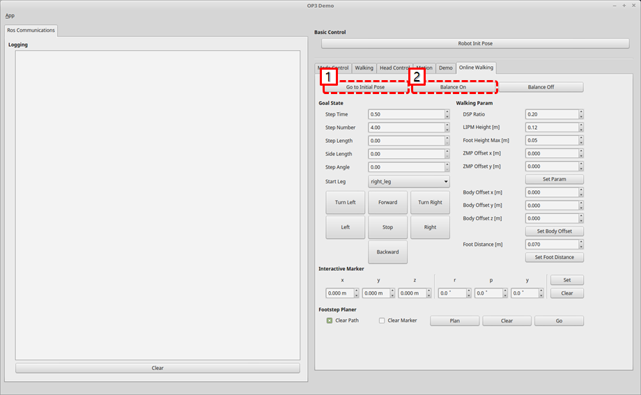
-
Set a interactive marker in rviz 3d screen and Move the marker to the target pose of feet.
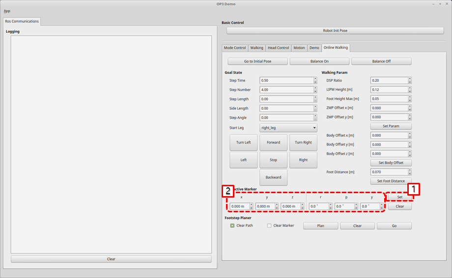
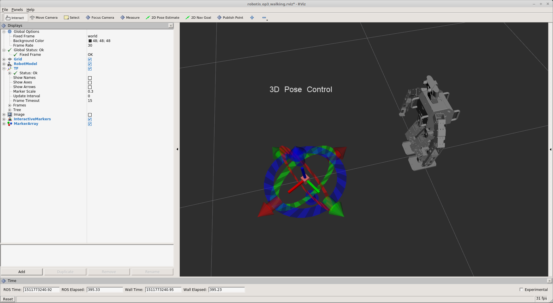
-
plan the path and send a walking message to ROBOTIS-OP3
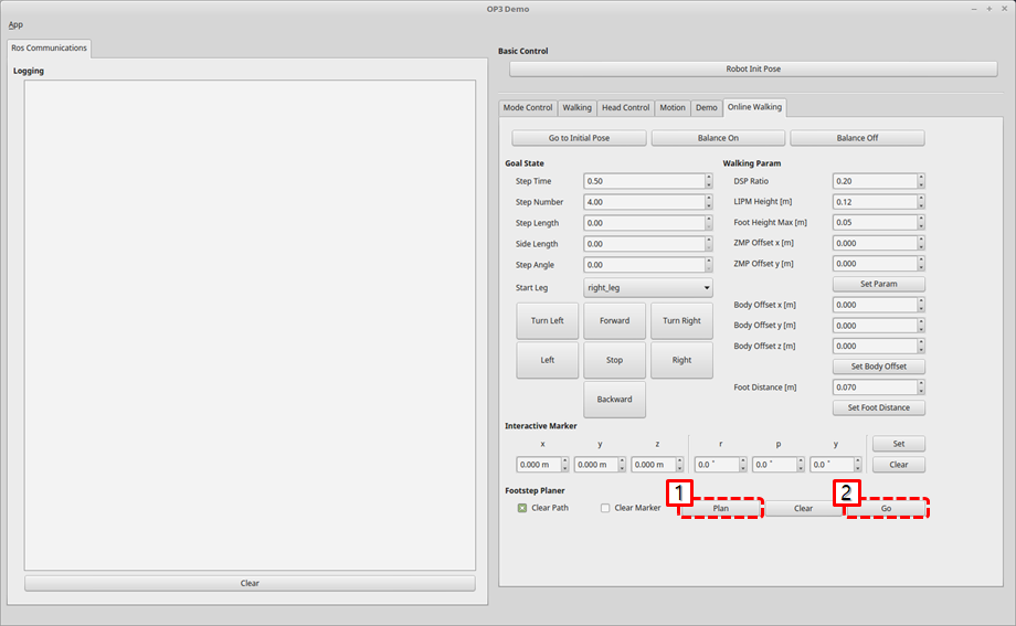
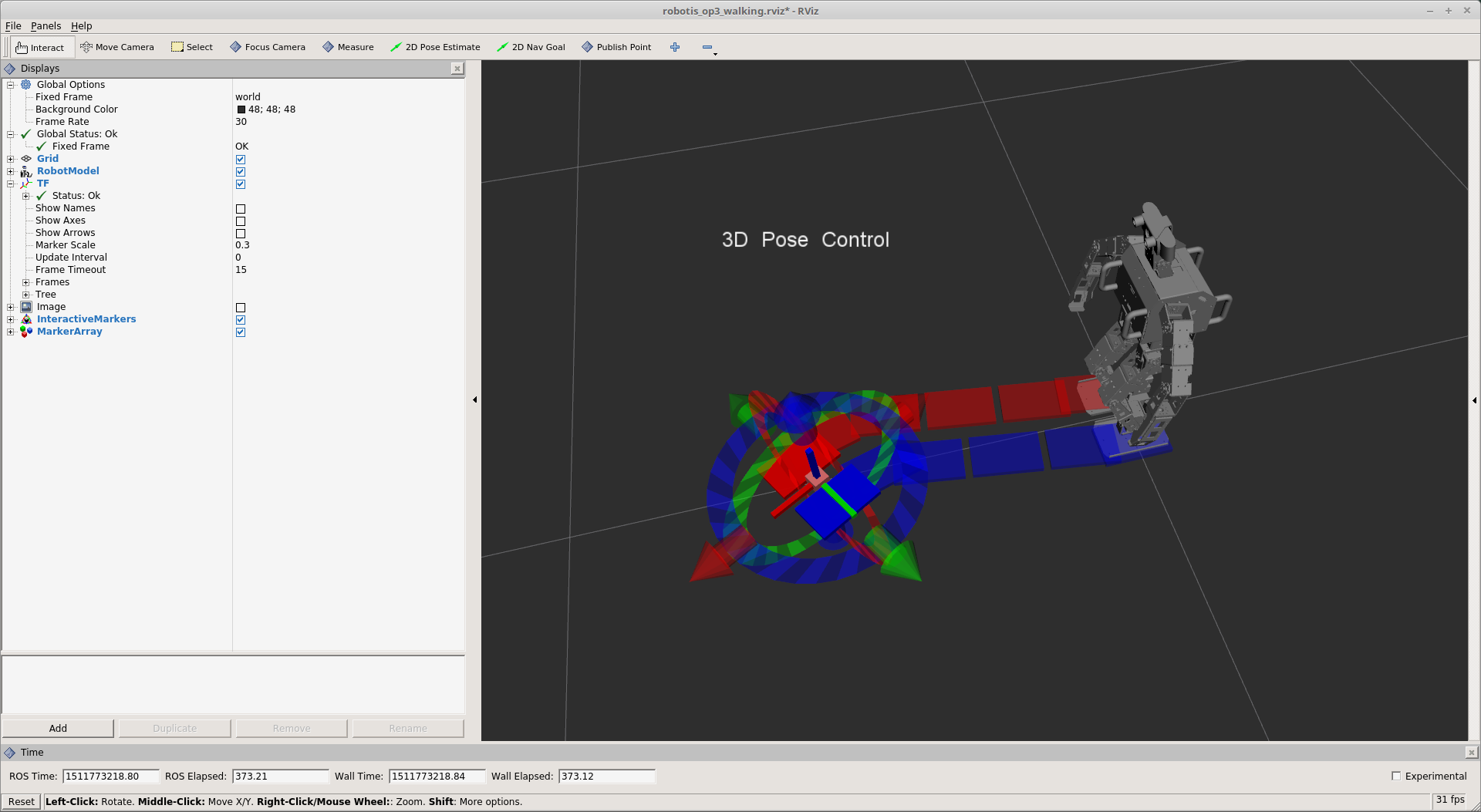
How to use Web Setting Tool
Overview
This chapter explains how to set the parameters of ROBOTIS-OP3 through a web page.
Reference : ROBOT WEB TOOL
Reference : web_video_server
Reference : rosbridge_server
Getting started
Installation
- web_video_server
$ sudo apt install ros-kinetic-web-video-server - rosbridge_server
$ sudo apt install ros-kinetic-rosbridge-server - Update and build source
- ROBOTIS-OP3-Demo
$ cd ~/catkin_ws/src/ROBOTIS-OP3-Demo $ git pull - ROBOTIS-OP3-Tools
$ cd ~/catkin_ws/src/ROBOTIS-OP3-Tools $ git pull - Build source
$ cd ~/catkin_ws
$ catkin_make
- ROBOTIS-OP3-Demo
- Setup the Web Server
- Install web server(APACHE2)
$ sudo apt install apache2 - Check the default page from a web browser
- http://10.42.0.1
- Install web server(APACHE2)
- Copy files from ROBOTIS-OP3-Tools folder to the web server folder : github
$ cd ~/catkin_ws/src/ROBOTIS-OP3-Tools/op3_web_setting
$ sudo cp -r ./html /var/www
How to connect ROBOTIS-OP3 WiFi
Connect to ROBOTIS-OP3 WiFi with below information
- WiFi ssid : ROBOTIS-OP3-Share
-
password : 11111111
For security reasons, it is recommended to change the WiFi password.Reference : How to connect
How to run web setting tool
- How to run the packages manually for web server
$ roslaunch op3_web_setting_tool web_setting_server.launch
How to set parameters
Menu
- Demo : Control default demo of ROBOTIS-OP3.
- Soccer : Setting for ball_detector.
- Vision : View the status of the detected face.
- Action : Testing ROBOTIS-OP3 actions.
- Camera : Change the parameters of ROBOTIS-OP3 camera.
Ball Detector parameters
Modified parameter values will be saved automatically.
- gaussian blur size: Size of Gaussian Blur Kernel (odd value)
- gaussian blur sigma: Standard deviation of Gaussian Blur
- canny edge threshold: Threshold of the edge detector
- hough accum resolution: Resolution of the Hough accumulator, in terms of inverse ratio of image resolution
- min circle distance: Minimum distance between circles
- hough accum threshold: Accumulator threshold to decide center detection
- min radius: Minimum circle radius allowed, pixels. (if unknown, set to 0 as a default.)
- max radius: Maximum circle radius allowed, pixels. (if unknown, set to 0 as a default.)
- ellipse size: Ellipse size
- Hue min: Minimum threshold of H filter
- Hue max: Maximum threshold of H filter
- Saturation min: Minimum threshold of S filter
- Saturation max: Maximum threshold of S filter
- Value min: Minimum threshold of V filter
- Value max: Maximum threshold of V filter
- Debug image: Show filtered image to debug
- Normal image : Show normal image
- Reset parameters : reset all of parameters
Reference : detail of parameter
Camera Setting parameters
Modified parameter values will be saved automatically.
Read-Write Tutorial
Overview
This chapter explains to user how to get joint angles of ROBOTIS-OP3 and how to set their values.
Framework Diagram
This is a framework diagram. The framework(op3_manager) works in the following way.
- Initialization
- Add sensors and motion modules
-
Start the timer and run threads
Execute the process function within the thread at a cycle of 8ms.
The process function performs the following operations according to the mode.-
DirectControlMode : This mode directly controls the robot using topics received from the user.
- BulkRead RX : Received rx packet containing joint information of each DYNAMIXEL
- SyncWrite : Transmit joint values to the multiple DYNAMIXEL’s to control
- BulkRead TX : Transmit tx packet to get information of dynamixel
- Call
process()function of each sensor module - Publish a topic that contains present & goal joint states
-
MotionModuleMode : This mode controls the robot using motion module.
- BulkRead RX : Received rx packet containing joint information of each DYNAMIXEL
- SyncWrite : Transmit goal values(position, velocity, current, position PID gain, velocity PID gain) to multiple DYNAMIXEL’s
- BulkRead TX : Transmit tx packet to get information of dynamixel
- Call
process()function of each sensor module - Call
process()function of each motion module - Publish a topic that contains present & goal joint states
-
Description
How to Get Joint States
motion_moduleuses joint states inside of theop3_manager.
If user creates and uses a motion_module, user can get additional information by adding a bulkread item.
bulkread item is added by modifying [OP3.robot] file.
In robotis_controller, when the process() function of each motion_module is called, two arguments pass the imformation about joint.robot_-> dxls_contains information about each joint.sensor_result_contains information about the sensor.
- Other ROS packages use joint states outside of the
op3_manager.
The process function in robotis_controller reads the information of each joint and publishes it as a topic.- topic name :
/robotis/present_joint_states - Containing Information : present position, present velocity, present effort, goal position, goal velocity, goal effort
- topic name :
How to Set Joint States
op3_manager provides a way to control each joint of the robot with the following two methods.
robotis_controller
If the control mode of the robotis_controller meets one of the below two conditions, the user can directly control joints of the robot using the/robotis /set_joint_statestopic.- DirectControlMode
- none of the activating module under the MotionModuleMode
motion_module:direct_control_module
User can directly control joints of the robot usingdirect_control_modulethat is one of the motion modules.
Users can implement features in the motion module.direct_control_modulehas a simple self-collision checking(check the distance between end-effector and COB).
The topic name to control the robot is/robotis/direct_control/set_joint_states.
Reference : SyncWriteItem
Framework providesSyncWriteItem, a way to write to devices aperiodically.
If user send aSyncWriteItemmessage with the name of/robotis/sync_write_item, Framework try to sync-write to devices with those message.
Read-Write Demo
Download & Build
Reference : Installing ROBOTIS ROS Package
How to Run Demo
Stop the default demo
$ sudo service OP3-demo stop
[sudo] password for robotis: 111111
Run read-write demo
$ roslaunch op3_read_write_demo op3_read_write.launch
op3_read_write.launch
<?xml version="1.0" ?>
<launch>
  <param name="gazebo"                   value="false"    type="bool"/>
  <param name="gazebo_robot_name"        value="robotis_op3"/>

  <param name="offset_file_path"         value="$(find op3_manager)/config/offset.yaml"/>
  <param name="robot_file_path"          value="$(find op3_manager)/config/OP3.robot"/>
  <param name="init_file_path"           value="$(find op3_manager)/config/dxl_init_OP3.yaml"/>
  <param name="device_name"              value="/dev/ttyUSB0"/>

  <param name="/robotis/direct_control/default_moving_time"     value="0.04"/>
  <param name="/robotis/direct_control/default_moving_angle"    value="90"/>

  <!-- OP3 Manager -->
  <node pkg="op3_manager" type="op3_manager" name="op3_manager" output="screen">
    <param name="angle_unit" value="30" />
  </node>

  <!-- OP3 Localization -->
  <node pkg="op3_localization" type="op3_localization" name="op3_localization" output="screen"/>

  <!-- OP3 Read-Write demo -->
  <node pkg="op3_read_write_demo" type="read_write" name="op3_read_write" output="screen"/>
</launch>
- parameters
gazebo: parameter for gazebo simulationgazebo_robot_name: robot name for gazebo simulationoffset_file_path: The file path containing the offset value of each joint, used by op3_manager.robot_file_path: The file path containing the robot informationinit_file_path: The file path containing the initial parameters of jointsdevice_name: device name to communicate with robot/robitis/direct_control/default_moving_time: minimum moving time for direct_control_module/robitis/direct_control/default_moving_angle: moving angle per 1 sec, used in direct_control_module
- node
op3_manager: This node controls ROBOTIS-OP3 hardwareop3_localization: simple localization node for op3_online_walkingop3_read_write: read-write demo, described in this chapter
- rqt_graph
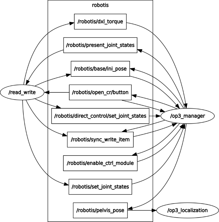
How to Operate
- Description : Buttons
From the left :modebutton,startbutton,userbutton,resetbuttonmodebutton : start read_write demo usingrobotis_controllerstartbutton : start read_write demo usingdirect_control_moduleuserbutton : torque on all jointsresetbutton : torque off all joints
Source Code
-
#include <ros/ros.h> #include <std_msgs/String.h> #include <sensor_msgs/JointState.h> #include "robotis_controller_msgs/SetModule.h" #include "robotis_controller_msgs/SyncWriteItem.h" void buttonHandlerCallback(const std_msgs::String::ConstPtr& msg); void jointstatesCallback(const sensor_msgs::JointState::ConstPtr& msg); void readyToDemo(); void setModule(const std::string& module_name); void goInitPose(); void setLED(int led); bool checkManagerRunning(std::string& manager_name); void torqueOnAll(); void torqueOff(const std::string& body_side); enum ControlModule { None = 0, DirectControlModule = 1, Framework = 2, }; const int SPIN_RATE = 30; const bool DEBUG_PRINT = false; ros::Publisher init_pose_pub; ros::Publisher sync_write_pub; ros::Publisher dxl_torque_pub; ros::Publisher write_joint_pub; ros::Publisher write_joint_pub2; ros::Subscriber buttuon_sub; ros::Subscriber read_joint_sub; ros::ServiceClient set_joint_module_client; int control_module = None; bool demo_ready = false; //node main int main(int argc, char **argv) { //init ros ros::init(argc, argv, "read_write"); ros::NodeHandle nh(ros::this_node::getName()); init_pose_pub = nh.advertise<std_msgs::String>("/robotis/base/ini_pose", 0); sync_write_pub = nh.advertise<robotis_controller_msgs::SyncWriteItem>("/robotis/sync_write_item", 0); dxl_torque_pub = nh.advertise<std_msgs::String>("/robotis/dxl_torque", 0); write_joint_pub = nh.advertise<sensor_msgs::JointState>("/robotis/set_joint_states", 0); write_joint_pub2 = nh.advertise<sensor_msgs::JointState>("/robotis/direct_control/set_joint_states", 0); read_joint_sub = nh.subscribe("/robotis/present_joint_states", 1, jointstatesCallback); buttuon_sub = nh.subscribe("/robotis/open_cr/button", 1, buttonHandlerCallback); // service set_joint_module_client = nh.serviceClient<robotis_controller_msgs::SetModule>("/robotis/set_present_ctrl_modules"); ros::start(); //set node loop rate ros::Rate loop_rate(SPIN_RATE); // wait for starting of op3_manager std::string manager_name = "/op3_manager"; while (ros::ok()) { ros::Duration(1.0).sleep(); if (checkManagerRunning(manager_name) == true) { break; ROS_INFO_COND(DEBUG_PRINT, "Succeed to connect"); } ROS_WARN("Waiting for op3 manager"); } readyToDemo(); //node loop while (ros::ok()) { // process //execute pending callbacks ros::spinOnce(); //relax to fit output rate loop_rate.sleep(); } //exit program return 0; } void buttonHandlerCallback(const std_msgs::String::ConstPtr& msg) { // starting demo using robotis_controller if (msg->data == "mode") { control_module = Framework; ROS_INFO("Button : mode | Framework"); readyToDemo(); } // starting demo using direct_control_module else if (msg->data == "start") { control_module = DirectControlModule; ROS_INFO("Button : start | Direct control module"); readyToDemo(); } // torque on all joints of ROBOTIS-OP3 else if (msg->data == "user") { torqueOnAll(); control_module = None; } } void jointstatesCallback(const sensor_msgs::JointState::ConstPtr& msg) { if(control_module == None) return; sensor_msgs::JointState write_msg; write_msg.header = msg->header; for(int ix = 0; ix < msg->name.size(); ix++) { std::string joint_name = msg->name[ix]; double joint_position = msg->position[ix]; // mirror and copy joint angles from right to left if(joint_name == "r_sho_pitch") { write_msg.name.push_back("r_sho_pitch"); write_msg.position.push_back(joint_position); write_msg.name.push_back("l_sho_pitch"); write_msg.position.push_back(-joint_position); } if(joint_name == "r_sho_roll") { write_msg.name.push_back("r_sho_roll"); write_msg.position.push_back(joint_position); write_msg.name.push_back("l_sho_roll"); write_msg.position.push_back(-joint_position); } if(joint_name == "r_el") { write_msg.name.push_back("r_el"); write_msg.position.push_back(joint_position); write_msg.name.push_back("l_el"); write_msg.position.push_back(-joint_position); } } // publish a message to set the joint angles if(control_module == Framework) write_joint_pub.publish(write_msg); else if(control_module == DirectControlModule) write_joint_pub2.publish(write_msg); } void readyToDemo() { ROS_INFO("Start Read-Write Demo"); // turn off LED setLED(0x04); torqueOnAll(); ROS_INFO("Torque on All joints"); // send message for going init posture goInitPose(); ROS_INFO("Go Init pose"); // wait while ROBOTIS-OP3 goes to the init posture. ros::Duration(4.0).sleep(); // turn on R/G/B LED [0x01 | 0x02 | 0x04] setLED(control_module); // change the module for demo if(control_module == Framework) { setModule("none"); ROS_INFO("Change module to none"); } else if(control_module == DirectControlModule) { setModule("direct_control_module"); ROS_INFO("Change module to direct_control_module"); } else return; // torque off : right arm torqueOff("right"); ROS_INFO("Torque off"); } void goInitPose() { std_msgs::String init_msg; init_msg.data = "ini_pose"; init_pose_pub.publish(init_msg); } void setLED(int led) { robotis_controller_msgs::SyncWriteItem syncwrite_msg; syncwrite_msg.item_name = "LED"; syncwrite_msg.joint_name.push_back("open-cr"); syncwrite_msg.value.push_back(led); sync_write_pub.publish(syncwrite_msg); } bool checkManagerRunning(std::string& manager_name) { std::vector<std::string> node_list; ros::master::getNodes(node_list); for (unsigned int node_list_idx = 0; node_list_idx < node_list.size(); node_list_idx++) { if (node_list[node_list_idx] == manager_name) return true; } ROS_ERROR("Can't find op3_manager"); return false; } void setModule(const std::string& module_name) { robotis_controller_msgs::SetModule set_module_srv; set_module_srv.request.module_name = module_name; if (set_joint_module_client.call(set_module_srv) == false) { ROS_ERROR("Failed to set module"); return; } return ; } void torqueOnAll() { std_msgs::String check_msg; check_msg.data = "check"; dxl_torque_pub.publish(check_msg); } void torqueOff(const std::string& body_side) { robotis_controller_msgs::SyncWriteItem syncwrite_msg; int torque_value = 0; syncwrite_msg.item_name = "torque_enable"; if(body_side == "right") { syncwrite_msg.joint_name.push_back("r_sho_pitch"); syncwrite_msg.value.push_back(torque_value); syncwrite_msg.joint_name.push_back("r_sho_roll"); syncwrite_msg.value.push_back(torque_value); syncwrite_msg.joint_name.push_back("r_el"); syncwrite_msg.value.push_back(torque_value); } else if(body_side == "left") { syncwrite_msg.joint_name.push_back("l_sho_pitch"); syncwrite_msg.value.push_back(torque_value); syncwrite_msg.joint_name.push_back("l_sho_roll"); syncwrite_msg.value.push_back(torque_value); syncwrite_msg.joint_name.push_back("l_el"); syncwrite_msg.value.push_back(torque_value); } else return; sync_write_pub.publish(syncwrite_msg); } -
Code Explanation
Themain ()function checks if the/op3_managernode is running. Otherwise, wait for it to run.// wait for starting of op3_manager std::string manager_name = "/op3_manager"; while (ros::ok()) { ros::Duration(1.0).sleep(); if (checkManagerRunning(manager_name) == true) { break; ROS_INFO_COND(DEBUG_PRINT, "Succeed to connect"); } ROS_WARN("Waiting for op3 manager"); }If
/op3_manageris running, take the initial posture for the demo and process the topic and service.readyToDemo(); //node loop while (ros::ok()) { // process //execute pending callbacks ros::spinOnce(); //relax to fit output rate loop_rate.sleep(); }When the button on the back of ROBOTIS-OP3 is pressed, it is processed by the following function.
modeandstartbuttons will start demo. If you pressuserbutton, torque of all joint will be turned on.
Before starting the demo, thereadyToDemo()function usesSyncWriteItemto turn off the right arm torque.void buttonHandlerCallback(const std_msgs::String::ConstPtr& msg) { // starting demo using robotis_controller if (msg->data == "mode") { control_module = Framework; ROS_INFO("Button : mode | Framework"); readyToDemo(); } // starting demo using direct_control_module else if (msg->data == "start") { control_module = DirectControlModule; ROS_INFO("Button : start | Direct control module"); readyToDemo(); } // torque on all joints of ROBOTIS-OP3 else if (msg->data == "user") { torqueOnAll(); control_module = None; } }If
op3_managerreceives the present value of the joint, it is processed by the following function according to demo mode.
Create a JointState message with the value of the left arm joint created by mirroring the value of the right arm joint, and pass it to theop3_manageras a topic based on each demo.void jointstatesCallback(const sensor_msgs::JointState::ConstPtr& msg) { if(control_module == None) return; sensor_msgs::JointState write_msg; write_msg.header = msg->header; for(int ix = 0; ix < msg->name.size(); ix++) { std::string joint_name = msg->name[ix]; double joint_position = msg->position[ix]; // mirror and copy joint angles from right to left if(joint_name == "r_sho_pitch") { write_msg.name.push_back("r_sho_pitch"); write_msg.position.push_back(joint_position); write_msg.name.push_back("l_sho_pitch"); write_msg.position.push_back(-joint_position); } if(joint_name == "r_sho_roll") { write_msg.name.push_back("r_sho_roll"); write_msg.position.push_back(joint_position); write_msg.name.push_back("l_sho_roll"); write_msg.position.push_back(-joint_position); } if(joint_name == "r_el") { write_msg.name.push_back("r_el"); write_msg.position.push_back(joint_position); write_msg.name.push_back("l_el"); write_msg.position.push_back(-joint_position); } } // publish a message to set the joint angles if(control_module == Framework) write_joint_pub.publish(write_msg); else if(control_module == DirectControlModule) write_joint_pub2.publish(write_msg); }