
NOTE: The OpenCM 485 EXP e-Manual in Japanese (日本語) is available for the Japanese.
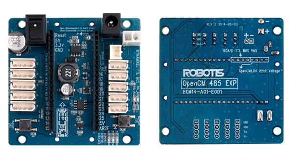
OpenCM 485 Expansion Board
Introduction
Specifications
| Item | Description |
|---|---|
| Input voltage | 5 ~ 30V |
| Power | SMPS, LiPo, DXL PRO 24V |
| Power Switch | 1 |
| DYNAMIXEL Port | 4Pin x 5, 3Pin x 5 |
| Button | 2 |
| LED | 5 |
| Size | 68 mm X 66.5 mm |
| Weight | 32g |
| Serial3 TX | Header Pin #24 |
| Serial3 RX | Header Pin #25 |
| Direction Control | Header Pin #22 |
![]()
위험
(심각한 상해 또는 사망에 이르게 할 수 있습니다.)
- 제품 주위에 가연성 물질, 계면활성제, 음료수, 물을 분사하거나 흡입시키지 마세요.
- 작동 중인 제품에 손, 발과 같은 신체 또는 신체의 일부를 넣지 마세요.
- 제품에서 이상한 냄새가 나거나, 연기가 발생하면 전원 연결을 즉시 끊어주세요.
- 아이들이 제품으로 장난치지 않도록 하세요.
- 전원공급 시 극성을 반드시 확인해 주세요.
![]()
경고
(상해나 제품 손상의 원인이 됩니다.)
- 제품의 사용 환경을 준수하세요. (전압, 온도 등)
- 작동 중인 제품 내부로 칼날, 압정, 불씨 등을 흡입시키지 마세요.
![]()
주의
(상해나 제품 손상의 원인이 됩니다.)
- 제품을 사용자 임의로 분해 또는 개조하지 마세요.
- 제품에 강한 충격을 가하거나 떨어드리지 마세요.
Layout
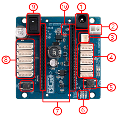
- SMPS DC Connector (2.5mm ID / 5.5mm OD, Center Positive) : For using SMPS DC Adapter to supply power to OpenCM 485 EXP board.
- DXL Pro Power Connector : Power connector for DYNAMIXEL Pro (24V).
- Li-Po battery Connector : Connector for 11.1V Li-Po battery(LBS-10).
- DYNAMIXEL TTL 3 -Pin Bus : Used to connect 3-Pin Cables(DYNAMIXEL TTL Bus) and for daisy chaining DYNAMIXEL’s.
- User Button : Function of these buttons can be assigned by the user.
- User LED : LED that can be controlled by the user.
- I/O header : Header pins used to mount OpenCM9.04(2.54mm pitch).
- DYNAMIXEL 485 4-Pin Bus : Used to connect 4-Pin Cables(DYNAMIXEL TTL Bus) and for daisy chaining DYNAMIXEL’s.
- Power Switch : Switch that powers the board and DYNAMIXEL. Note: Does not disconnect the power received via USB cable.
- JP1 Jumper : Jumper that determines whether the power inputted onto OpenCM 485 EXP will be supplied to OpenCM9.04 board or not.
WARNING: To enhance user safety and to prevent proprietary risk or damage, be sure to check the pinout installed on DYNAMIXEL and the board. The Pinout of DYNAMIXEL may differ depending on a manufacturer of connector.
Using with OpenCM9.04
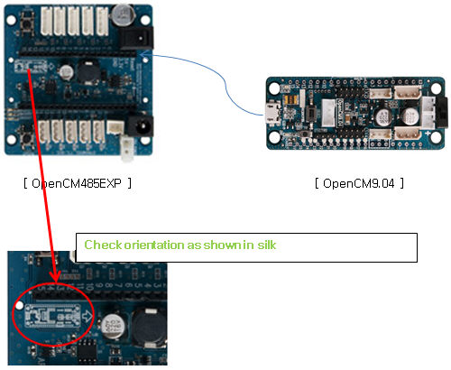
Connecting OpenCM9.04 to the expanstion board
-
Prepare OpenCM 485 EXP and OpenCM9.04 boards. Any version of OpenCM9.04 is compatible. Solder the header onto the OpenCM9.04.
-
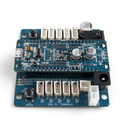
OpenCM9.04 is mounted onto OpenCM 485 EXP as shown below.
CAUTION : Be sure to check the direction of the OpenCM9.04 when inserting it into the OpenCM 485 EXP board.
-
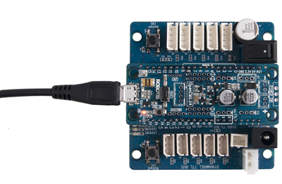
Connect the USB cable onto OpenCM9.04 board.
-
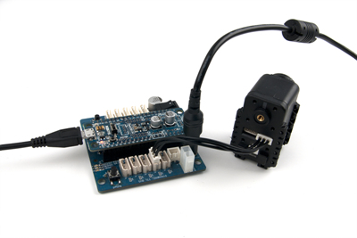
Connect DYNAMIXEL and 12V SMPS adapter onto OpenCM 485 EXP board.
NOTE:
- DYNAMIXEL-X and P series use JST connector that is not compatible with a connector installed on the OpenCM 485 EXP board. To use DYNAMIXEL X and P series with the expansion board, use JST-Molex convertable cable.
- Be sure to disconnect OpenCM9.04 with OpenCM 485 EXP board before a firmware recovery for DYNAMIXEL.
Using DYNAMIXEL-X
To use ROBOTIS software (R+ Task, R+ Motion 및 R+ Manager) with DYNAMIXEL-X series, Configuring DYNAMIXEL Channle is required.
NOTE: Arduino IDE does not require DYNAMIXEL Channel configuration.
NOTE: DYNAMIXEL-X and P series use a JST connector. To use DYNAMIXEL X and P series with the expansion board, use Robot Cable-X3P (Convertible) or Robot Cable-X4P (Convertible).
Configuring DYNAMIXEL Channel
Change DYNAMIXEL Channel’s item to use various DYNAMIXEL-X series.
NOTE:
- Keep a version of firmware up-to-date.
- If OpenCM485 board and OpenCM9.04 are connected, make sure to separate it before Firmware Update or Firmware Recovery.
-
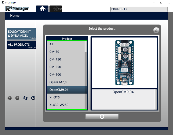
Open R+ Manager, and select OpenCM 9.04 in the Home tab.
-
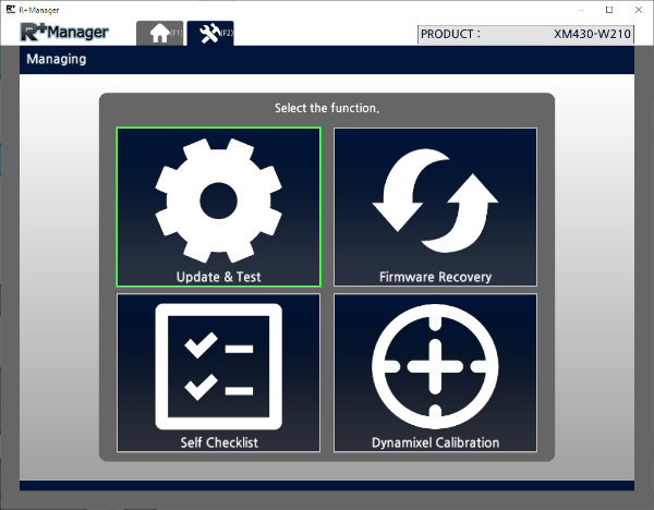
Select Update & Test.
-
When the control table appears, select an DYNAMIXEL’s bus channel on the list of Dynamixel Channel. For example, select EXP Board(X-Series) to use DYNAMIXEL-X series on the expansion board.
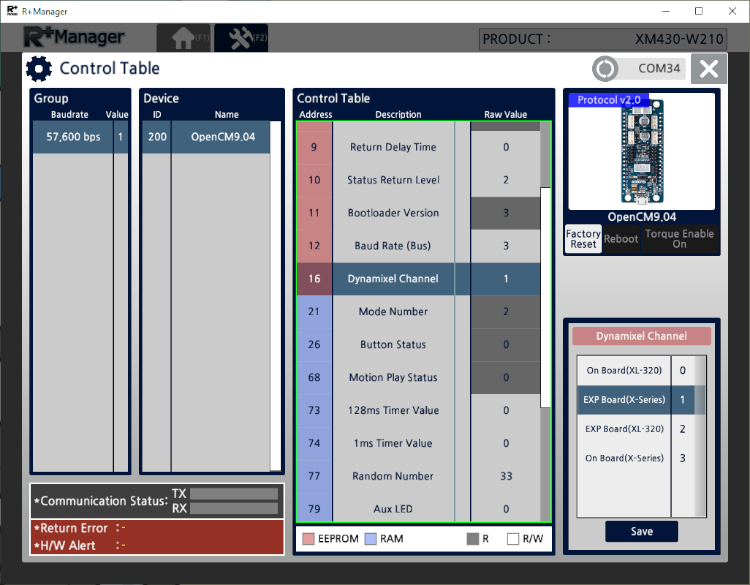
| Item | Description |
|---|---|
| On Board(XL-320) | Uses XL-320 only with the OpenCM 9.04 on ROBOTIS Software (R+ Motion and R+ Task) |
| EXP Board(X-Series) | Uses DYNAMIXEL-X series, XL-320 excluded, with the expantion board on ROBOTIS Software (R+ Motion and R+ Task) |
| EXP Board(XL-320) | Uses XL-320 only with the expantion board on ROBOTIS Software (R+ Motion and R+ Task) |
| On Board(X-Series) | Uses DYNAMIXEL-X series, XL-320 excluded, with the OpenCM 9.04 on ROBOTIS Software (R+ Motion and R+ Task) |
NOTE: After setup is complete, restart the OpenCM9.04 or the expansion board to activate DYNAMIXEL’s bus channel. Consequently, the DYNAMIXEL with the controller will properly work on the motion tool or with the motion file on the task program.
Reference
Connector Information
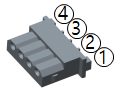
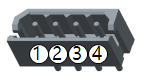
| Item | TTL | RS-485 | Power |
|---|---|---|---|
| Pinout | 1 GND2 VDD3 DATA |
1 GND2 VDD3 DATA+4 DATA- |
1 GND2 VDD |
| Diagram |  |
 |
 |
| Housing | 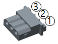 MOLEX 50-37-5033 |
 MOLEX 50-37-5043 |
 MOLEX 39-01-2020 |
| PCB Header | 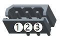 MOLEX 22-03-5035 |
 MOLEX 22-03-5045 |
 MOLEX 39-28-1023 |
| Crimp Terminal | MOLEX 08-70-1039 | MOLEX 08-70-1039 | MOLEX 39-00-0038 |
| Wire Gauge for DYNAMIXEL | 21 AWG | 21 AWG | 20 AWG |
WARNING: To enhance user safety and to prevent proprietary risk or damage, be sure to check the pinout installed on DYNAMIXEL and the board. The Pinout of DYNAMIXEL may differ depending on a manufacturer of connector.
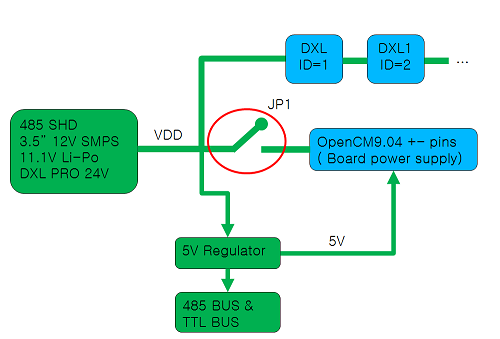
Power Circuit Connection
A power circuit block diagram of the OpenCM 485 EXP and OpenCM9.04, once mounted, is shown below.
OpenCM 485 EXP can supply 5V to OpenCM9.04 when connected to a power source. JP1 can be used to determine whether the VDD power from OpeCM 485 EXP board is supplied to OpenCM9.04 DYNAMIXEL ports.
OpenCM 485 EXP Power Connection
OpenCM 485 EXP’s DYNAMIXEL 485 bus operates as DYNAMIXEL bus using OpenCM9.04’s USART3(Serial3).
NOTE : OpenCM9.04’s DYNAMIXEL TTL BUS is connected to USART1(Serial1).
OpenCM9.04 & OpenCM 485 EXP Bus Connections
EXP Board Programming
In order to use OpenCM 485 EXP board with OpenCM9.04, please use Arduino IDE.
-
OpenCM 485 EXP’s 485 Bus sends and receives communication packets via OpenCM9.04’s Serial3(USART3).
- In case of programming with DYNAMIXEL SDK, please set Serial3 port as shown below.
#include <DYNAMIXEL SDK.h> #define DEVICENAME "3" //Use Serial3 port dynamixel::PortHandler *portHandler = dynamixel::PortHandler::getPortHandler(DEVICENAME); portHandler->openPort();- In case of programming with DYNAMIXELWorkbench, please set Serial3 port as shown below.
 #include <DYNAMIXELWorkbench.h>

 #define DEVICENAME      "3"   //Use Serial3 port
 #define BAUDRATE        57600

 DYNAMIXELWorkbench dxl_wb;
 dxl_wb.begin(DEVICE_NAME, BAUDRATE);
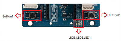
Button and LED
OpenCM 485 EXP board has 2 buttons and 3 LED’s that are connected to OpenCM9.04 I/O pins.
The OpenCM9.04 I/O pin numbers for the buttons and LED’s are indicated below.
| OpenCM9.04 I/O | |
|---|---|
| Button1 | 16 |
| Button2 | 17 |
| LED1 | 18 |
| LED2 | 19 |
| LED3 | 20 |
Drawings
Download PDFPCB Schematic