
Quick Start
Power On
The following instructions will walk you through the OP3 set up process.
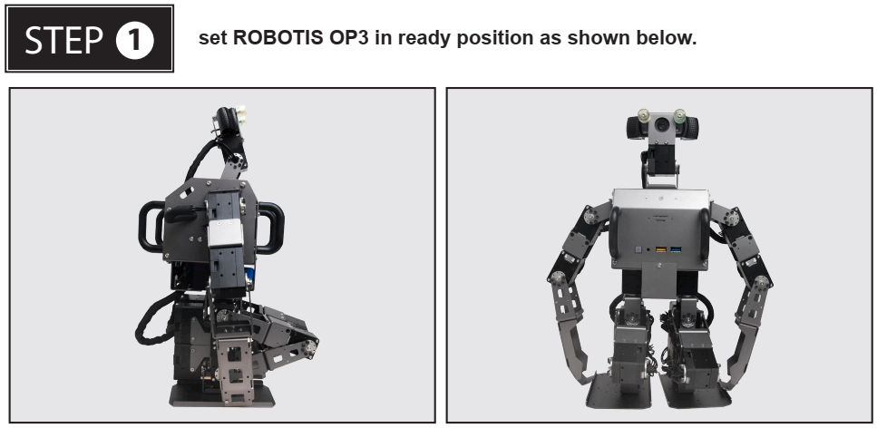
WARNING : Powering on the ROBOTIS OP3 in a position other than the pose shown above may cause mechanical damage when entering the initial stance on startup.
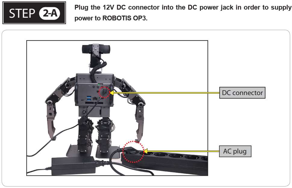
Connect the AC plug of the power adapter to a power outlet and plug the DC connector into the ROBOTIS OP3’s DC jack. The DC jack is located on the back panel of the ROBOTIS OP3.
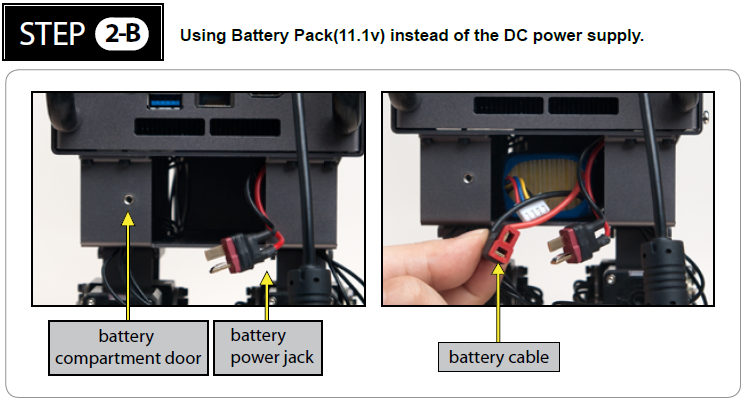
The ROBOTIS OP3 can be powered either from a DC power supply, or an onboard battery pack. If you would like to power your OP3 using an onboard battery, follow the procedure below:
- Ensure the battery pack is fully charged.
- Open the battery compartment door (unscrew the thumbscrew) and insert the battery pack.
- Connect the battery cable to the battery power jack.
- Close and secure the compartment door (screw the thumbscrew) afterwards.
- Disconnect DC power supply.
WARRNING : Please turn off the power switch before connecting any power source (battery or SMPS) to the product.
WARNING : Make sure the OpenCR is switched off when connecting a power source.
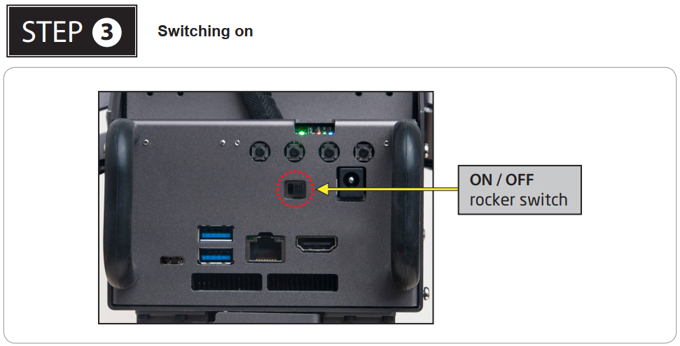
Pushing the power switch to the right will power up the ROBOTIS OP3 (to the right : power on, to the left : power off)
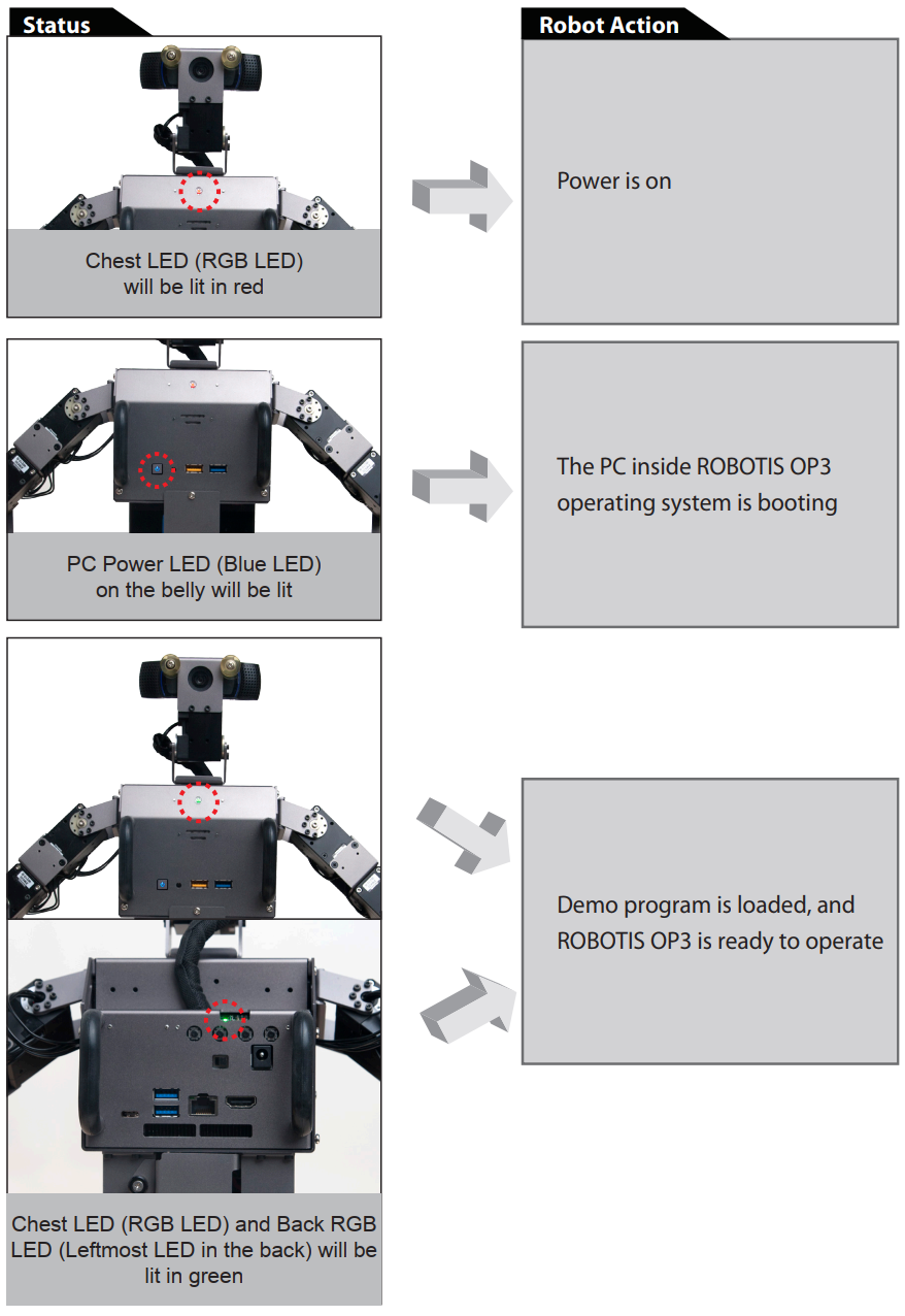
Once Power is switched on, the following startup procedure will be sequentially executed.
Execute Demo Program
Running Demonstration Programs
ROBOTIS OP3 is loaded with the following pre-configured demonstration modes:
- Demonstration-Ready Mode
- Autonomous Soccer Mode
- Vision Processing Mode
- Interactive Motion Mode
Demonstration-Ready mode is the default mode when the ROBOTIS OP3 is turned on.
Press the MODE button to change the active the mode.
ROBOTIS OP3 will verbally announce the selected mode when pressing the button.
The indicator LED will also change its color to the corresponding operation mode.
Press the START button to run the selected mode.
After pressing START, the ROBOTIS OP3 will stand up and begin operation.
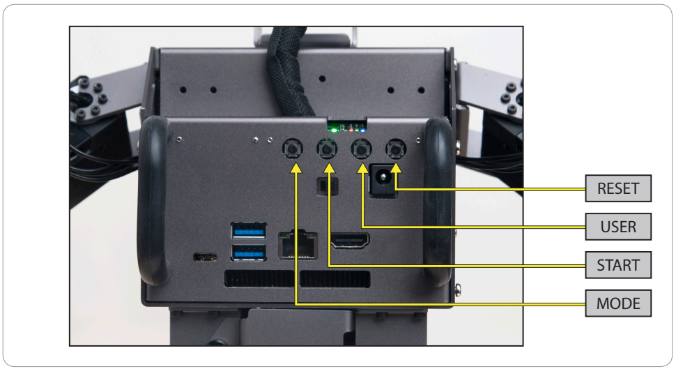
RESET Button
The RESET button only resets connected DYNAMIXEL actuators and the OpenCR sub-controller, not the entire system. Please keep in mind that the demo program is still running in the main controller when the RESET button is pressed.
Pressing RESET will disable torque on all actuators. It is highly recommended to set the ROBOTIS OP3 in a kneeling or sitting pose before pressing RESET or hold the ROBOTIS OP3 using its carrying handle.
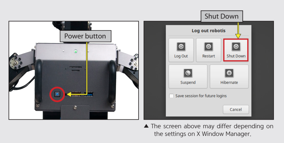
Demonstration Ready Mode
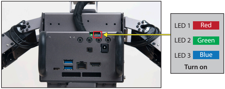
The Demonstration-Ready mode the default mode when ROBOTIS OP3 is turned on. LED 1 (red), LED 2 (green) and LED 3 (blue) will be lit.
The chest LED will switch the color from red to green while ROBOTIS OP3 verbally announces “Demonstration-ready mode”.
Now ROBOTIS OP3 is ready for action!
ROBOTIS OP3 stays in kneeling pose and does not move while in this mode.
This is the most recommended mode when changing the power source or otherwise handling the OP3.
Autonomous Soccer Mode
ROBOTIS OP3 follows and kicks a red ball (ball color is user configurable) and plays soccer by itself.
If the ROBOTIS OP3 falls down (either on its back or belly) it will stand up and resume ball tracking, then continue pursuit.
- Start Autonomous Soccer Mode
-
Press the
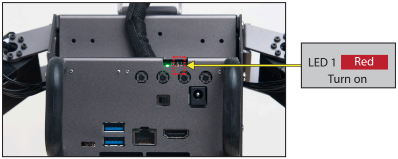
MODEbutton until LED1 (red) is lit.
ROBOTIS OP3 will verbally announce “Autonomous soccer mode”.
-
Press the
STARTbutton to begin.
ROBOTIS OP3 will stand up and walk around to find the ball, and verbally announce “Start soccer demonstration” -
When ROBOTIS OP3 sees a ball with a matching color, it will walk toward the ball.
If ROBOTIS OP3 gets close enough to the ball, ROBOTIS OP3 will kick the ball with one of its feet.
If ROBOTIS OP3 falls down during pursuit or kick, it will stand up and resume.
-
- Stop Autonomous Soccer Mode
- Press
MODEbutton until LED 3(blue) is lit. ROBOTIS OP3 will verbally announce “Interactive motion mode”.
- Press
Interactive Motion Mode
ROBOTIS OP3 performs pre-programmed motions sequentially while talking.
- Start Interactive Motion Mode
-
Press the
MODEbutton until LED 3 (blue) is lit. ROBOTIS OP3 will verbally announce “Interactive motion mode”.
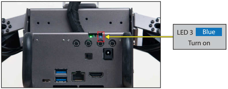
-
Press the
STARTbutton to begin. ROBOTIS OP3 will stand up and announce “Start motion demonstration”. -
The ROBOTIS OP3 will perform the following actions sequentially.
-
- Stop Interactive Motion Mode
- If the
MODEbutton is pressed for at least 2 seconds, ROBOTIS-OP3 will return to demonstration-ready mode.
- If the
Vision Processing Mode
The new vision processing demo for ROBOTIS OP3 is “Face detection and tracking”. Please refer the below website links for further information on the upstream sources for the libraries used.
[https://github.com/ROBOTIS-GIT/ROBOTIS-OP3-ETC]
face detection forked from https://github.com/phil333/face_detection
usb_cam forked from https://github.com/ros-drivers/usb_cam
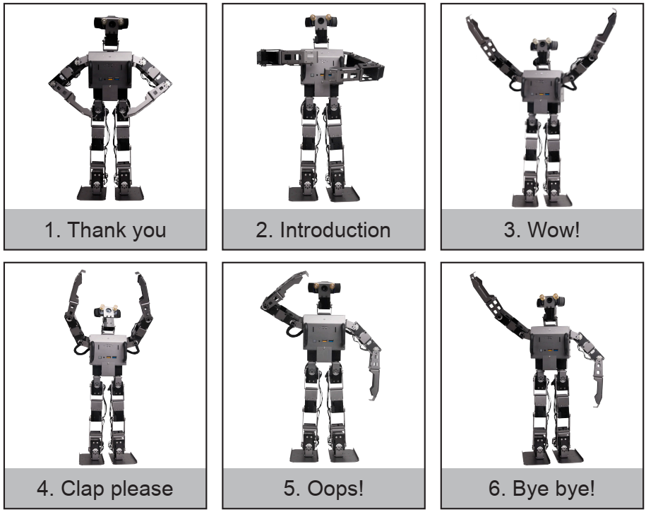
- Start Vision Processing Mode
-
Press the
MODEbutton until LED 2 (green) is lit. ROBOTIS OP3 will verbally announce “Vision processing mode”.
-
Press the
STARTbutton to begin. ROBOTIS OP3 will verbally announce “Start vision processing demonstration” and stand up. -
The target face should be located approximately 90cm (36”) away from ROBOTIS OP3.
If ROBOTIS OP3 detects the target face, the chest LED will illuminate white whereas the LED will be off if no face is detected.
ROBOTIS OP3 will keep track of the first recognized target face.
-
- Stop Vision Processing Mode
- If the
MODEbutton is pressed for at least 2 seconds, ROBOTIS-OP3 will return to Demonstration-Ready mode.
- If the
- ETC
- Modifying the parameters of the ‘face_detection’ package might improve recognition of the face. Please refer to the following websites for more details:
- face_detection package : https://github.com/ROBOTIS-GIT/ROBOTIS-OP3-ETC (face_detection)
- usb_cam package : https://github.com/ROBOTIS-GIT/ROBOTIS-OP3-ETC (usb_cam)
Camera Calibration
If ambient light surrounding the ROBOTIS OP3 is either too dim or too bright, you can adjust camera settings to optimize the acquired image from the camera and improve vision performance.
The color of the target ball for the soccer demo can also be modified using these settings.
Please refer to the ROBOTIS OP3 Camera Setting page for more information.
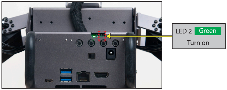
Power Off
Please perform the following procedure in order to in order to safely shutdown the computer inside ROBOTIS OP3.
-
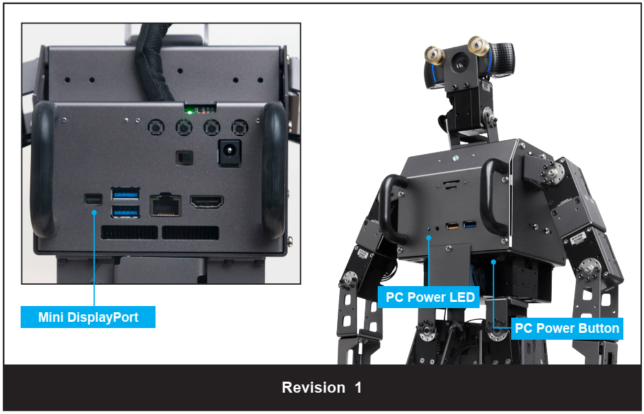
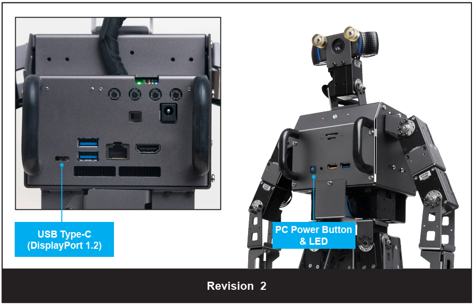
Press PC power button which is located on the belly. ROBOTIS OP3 will verbally announce “bye-bye” and initiate shutdown process.
When the internal computer of ROBOTIS OP3 is turned off, blue LED in the chest will turn off.
After the blue LED is turned off, shutdown the main power with the switch on the back of the robot. -
If ROBOTIS OP3 does not announce “bye-bye” then you may need to force shutdown by holding the power button until the blue LED in the chest turns off.
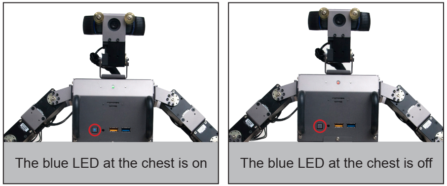
NOTE : If the power supply is cut off before the blue LED is turned off, ROBOTIS OP3 may have problems on the next startup.
Programming Guide
Connect to OP3
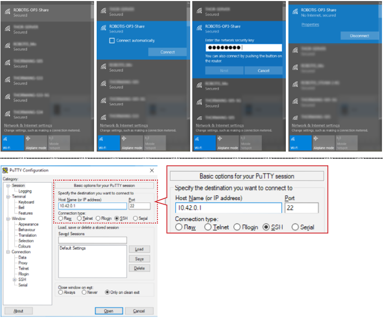
From your computer go to Wi-Fi Settings and set it to obtain an IP address automatically using DHCP.
Then connect to the ROBOTIS OP3 wifi network (SSID : ROBOTIS-OP3-share). The default password is 11111111.
Example : SSH Client (for Windows)
- Execute SSH client program (ex: PuTTY)
- Input ROBOTIS OP3’s IP address:
10.42.0.1 - Select
SSHas a connection type and open the connection. - Input ROBOTIS OP3’s user name :
robotis - Input ROBOTIS OP3’s Password :
111111
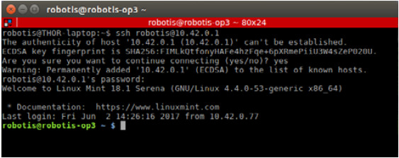
Example: SSH Client (for Linux)
- Open the terminal window.
- Input the following SSH command with ROBOTIS OP3’s user name and IP address :
$ ssh robotis@10.42.0.1 - Input ROBOTIS OP3’s Password :
111111
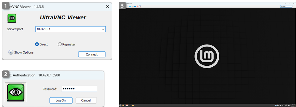
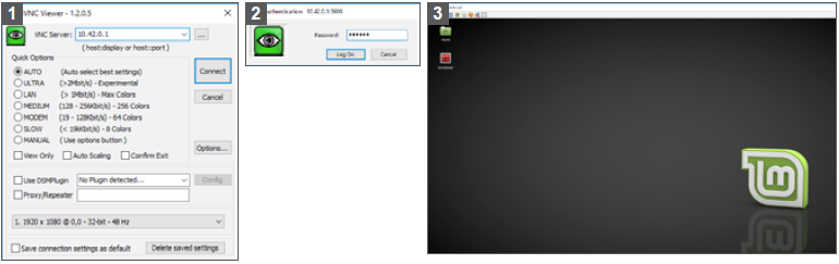
Example: VNC client (for Windows)
CAUTION : The robot must be booted with a physical monitor connected for a VNC connection to work.
- Users who are familiar with a graphical interface may use remote desktop software.
- Execute your VNC client program (ex: Ultra VNC Viewer)
- Input the ROBOTIS OP3’s IP address :
10.42.0.1 - Input the ROBOTIS OP3’s Password :
111111
Development Environment
The following is the list of tools for source code development.
- OS : Linux (64-bit)
- Compiler : GNU project C and C++ Compiler, colcon
- Programming Language : C++
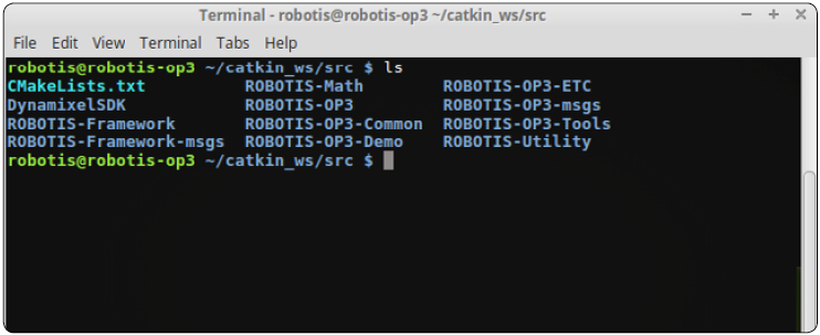
Source Code
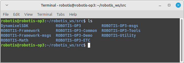
You may find the source code directory at /home/robotis/robotis_ws/src on the ROBOTIS OP3’s PC.
The pre-installed source code may be updated without prior notice. Please check for updates periodically. You may obtain updated source code from the below GitHub repositories:
- https://github.com/ROBOTIS-GIT/DynamixelSDK
branch:jazzy - https://github.com/ROBOTIS-GIT/ROBOTIS-Framework
branch:jazzy-devel - https://github.com/ROBOTIS-GIT/ROBOTIS-Framework-msgs
branch:jazzy-devel - https://github.com/ROBOTIS-GIT/ROBOTIS-Math
branch:jazzy-devel - https://github.com/ROBOTIS-GIT/ROBOTIS-OP3
branch:jazzy-devel - https://github.com/ROBOTIS-GIT/ROBOTIS-OP3-Common
branch:jazzy-devel - https://github.com/ROBOTIS-GIT/ROBOTIS-OP3-Demo
branch:jazzy-devel - https://github.com/ROBOTIS-GIT/ROBOTIS-OP3-ETC
branch:jazzy-devel - https://github.com/ROBOTIS-GIT/ROBOTIS-OP3-msgs
branch:jazzy-devel - https://github.com/ROBOTIS-GIT/ROBOTIS-OP3-Tools
branch:jazzy-devel - https://github.com/ROBOTIS-GIT/ROBOTIS-Utility
branch:jazzy-devel
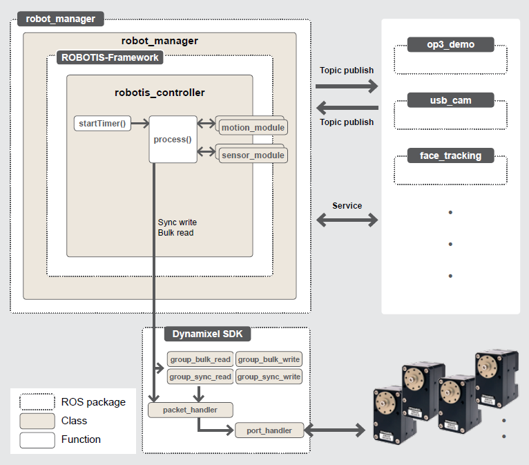
Framework
The following flow diagram represents an overview of the class breakdown and data pipelines for the OP3’s main framework.
You may modify the framework at /home/robotis/catkin_ws/src/ROBOTIS-Framework.
For more information, please refer to the WIKI.
ROBOTIS Framework WIKI
Software Utilities
User who wishes to customize or trooubleshoot ROBOTIS OP3 operation should establish a connection with the robot via SSH or Remote Desktop (VNC).
The tools are located in the following directory :
/home/robotis/catkin_ws/src/ROBOTIS-OP3-Tools
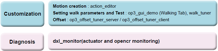
In this directory you can find code for :
- op3_action_editor : motion creation
- op3_gui_demo : configuring the motion control module, parameter tuning for walking, module testing features
- op3_tuner_client : adjust offset and gain for the ROBOTIS-OP3
- op3_camera_setting_tool : used with op3_manager to modify settings of the USB camera
- op3_web_setting_tool : used with op3_demo to modify settings via a web page
Recovery Software
The supplied USB thumb drive contains a copy of the the software pre-installed on the ROBOTIS OP3.
You may obtain updated software from the link below.
ROBOTIS OP3 Recovery
This software may be updated without prior notice. Please check for updates periodically.
Useful Information
You can download other ROBOTIS OP3-related items and more detailed information from the online manual.
ROBOTIS OP3 Tutorial
- For any inquiries send us an email.
- International :
contactus2@robotis.com - Korea :
korea@robotis.com - United States :
america@robotis.com
- International :
- Third party terminal client
- PuTTY : http://www.chiark.greenend.org.uk/~sgtatham/putty/
- RealVNC : http://www.realvnc.com/
Miscellaneous
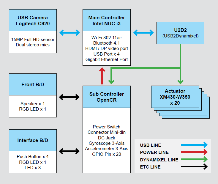
System Block Diagram
The diagram below illustrates the overall system structure of the ROBOTIS OP3.
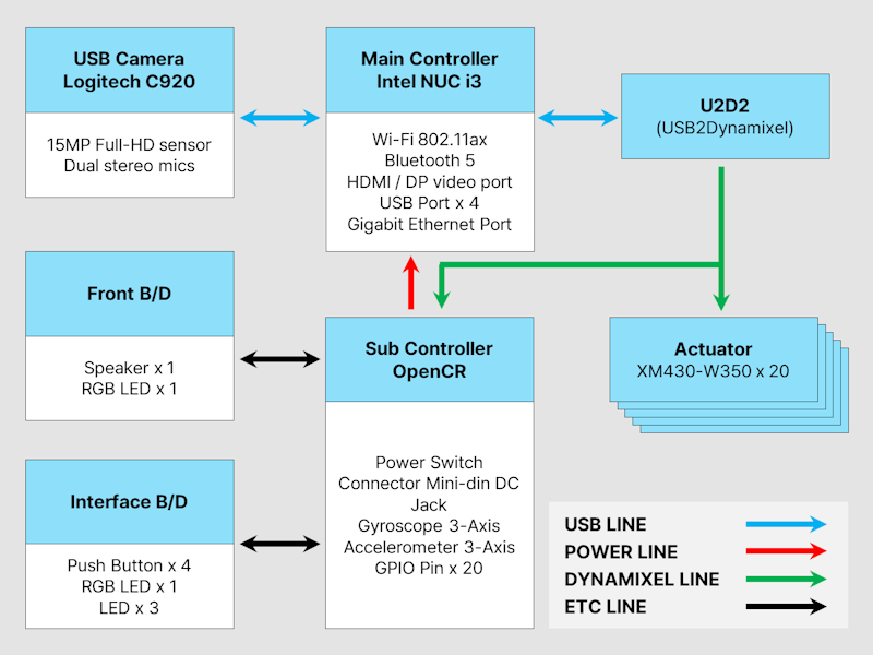
- The Main Controller is powered by a Intel i3 dual-core processor (Intel NUC i3)
- The Sub Controller is powered by a STMicroelectronics Cortex-M7 32F746GT6 microprocessor (clocked at 216MHz).
- Camera Information
- 1080p Full HD movie recording
- Carl Zeiss® optics with 20-step autofocus
- Built-in dual stereo mics with noise reduction
- H.264 video encoding
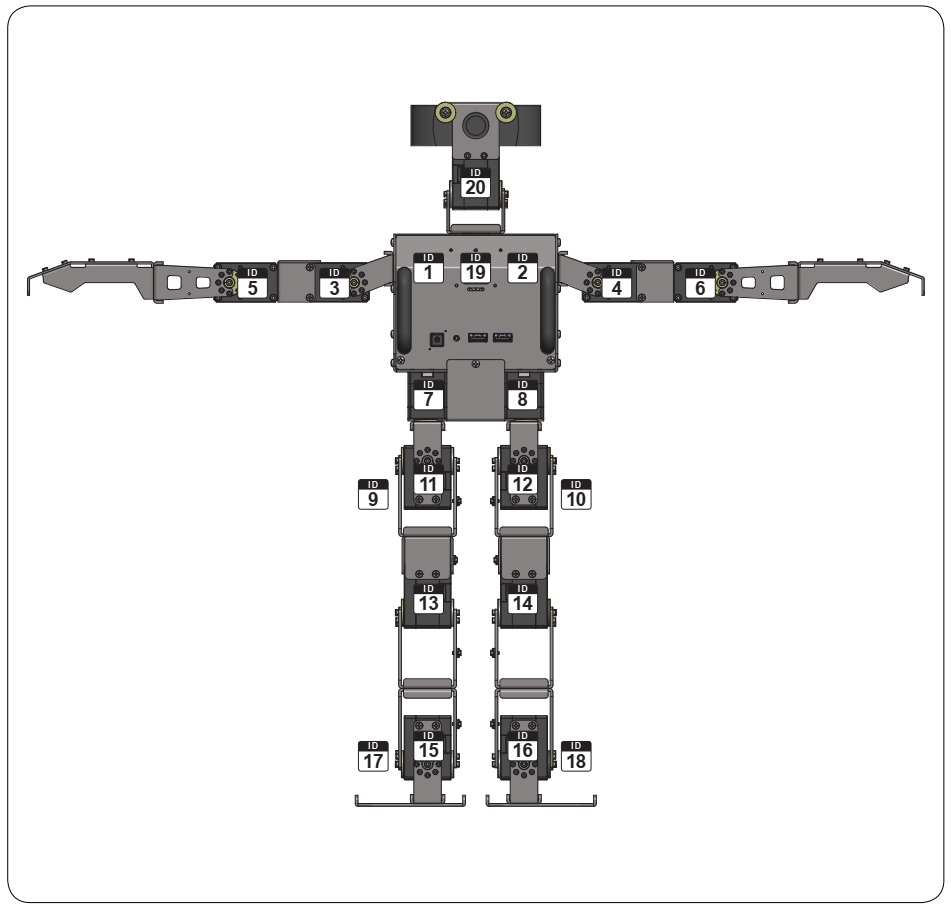
ID Map
The following diagram illustrates the default ID number for the actuators in the ROBOTIS OP3.
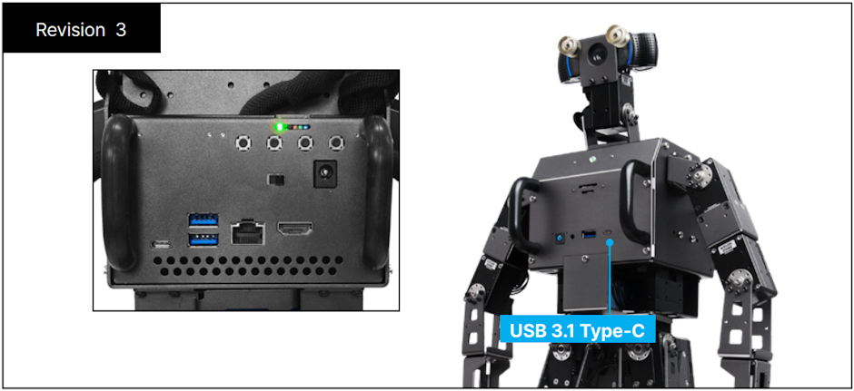
ROBOTIS-OP3 Revision
Different OP3 revisions can be identified by the included internal master PC.
Warranty
ROBOTIS OP3 includes the following warranty:
A. 90 day warranty against manufacturing defects (RMA required) *
B. Local Maintenance Service (by local partner) : 1 year **
- Re-installation of S/W and firmware
- Replacement for cable/gear/screw (RMA required – exempt from faulty return)
- Replacement for faulty frame/cover/actuator (RMA required)
C. Core System Maintenance Service (by ROBOTIS) : 1 year
- Replacement for faulty PC/sub-boards (RMA required)
- Maintenance for actuator/sub-boards (RMA required)
- Maintenance for PC (RMA required, additional fee applies)
D. Parts replacement for malfunctions during normal operation for 1 year.
Customers who require extended warranty period may purchase another “1 year warranty” from ROBOTIS before their standard warranty period is over.
Important Notice:
-
Product registration is required for all customers. http://support.robotis.com
-
Parts replacement can only be done through the RMA (Return Material Authorization) process.
-
After the initial 90 days, shipping fees are not covered under warranty.
- Warranty does NOT cover ordinary wear/tear, any accident or damage caused by the following:
- Physical damage equivalent to dropping the robot from 20cm or higher
- Disabling system safety functions (DYNAMIXEL Overload Shutdown)
- Dangerous movement (jumps, rolls, fights, etc.) or excessive operation without rest
- Any liquid or unauthorized chemical material applied the robot
- Unauthorized power or electric shock applied to the robot
- Improvising core system programming or other significant software modification.
- Direct check-up service
Evaluation, maintenance and quality assurance of the assembled robot can only be provided by ROBOTIS.
RMA is required and additional fees may apply. Service may not be rendered for heavily customized hardware.
Sub Controller(OpenCR)
WARRNING : Please turn off the power switch before connecting any power source (battery or SMPS) to the product.
Control Table
Control Table consists of data regarding the current status and operation of the OpenCR. The user can control the OpenCR by changing the data in the Control Table via Instruction packets.
EEPROM and RAM
Data in the RAM area is reset to initial values whenever the power is turned on while data in the EEPROM area is kept once values are configured even if the power is turned off.
Address
Represents the location of data in the control table. To read from or write data to the control table the user should assign the correct address in the Instruction packet.
Access
OpenCR has two kinds of data: Read-only data, used mainly for sensing, and read-and-write data used for control.
Initial Value
In the case of data in the EEPROM Area, the initial values on the right side of the following control table are the factory default settings.
In the case of data in the RAM Area, the initial values on the right side of the following control table are the ones when the power is turned on.
Highest/Lowest Byte
In the Control table, some data shares the same name, but feature a (L) or (H) at the end of each name to distinguish the address. This data requires 16-bit, but it is divided into multiple 8bit addresses (low) and (high). These two addresses should be written with one Instruction Packet simultaneously.
EEPROM Area
| Address | Name | Description | Access | Init Value |
|---|---|---|---|---|
| 0 (0X00) | Model Number(L) | model number low byte | R | 0(0X00) |
| 1 (0X01) | Model Number(H) | model number high byte | R | 116 (0X74) |
| 2 (0X02) | Version of Firmware | firmware version | R | - |
| 3 (0X03) | ID | OpenCR ID | RW | 200 (0XC8) |
| 4 (0X04) | Baud Rate | Communication baud rate | RW | 1 (0X01) |
| 5 (0X05) | Return Delay Time | Return Delay Time | RW | 0 (0X0) |
| 16 (0X10) | Status Return Level | Status Return Level | RW | 0 (0X00) |
RAM Area
| Address | Name | Description | Access | Init Value |
|---|---|---|---|---|
| 24 (0X18) | DYNAMIXEL Power | DYNAMIXEL On/Off | RW | 0 (0X00) |
| 25 (0X19) | LED | LED Pannel On/Off | RW | 0 (0X00) |
| 26 (0X1A) | LED_RGB(L) | LED 5 low byte | RW | 0 (0X00) |
| 27 (0X1B) | LED_RGB(H) | LED 5 high byte | RW | 0 (0X00) |
| 28 (0X1C) | Buzzer(L) | LED 6 low byte | RW | 0 (0X00) |
| 29 (0X1D) | Buzzer(H) | LED 6 high byte | RW | 0 (0X00) |
| 30 (0X1E) | Button | Button status | R | - |
| 31 (0X1F) | Voltage | Power Voltage | R | - |
| 32 (0X20) | Gyro_Z(L) | Gyroscope Z-axis low byte | R | - |
| 33 (0X21) | Gyro_Z(H) | Gyroscope Z-axis high byte | R | - |
| 34 (0X22) | Gyro_Y(L) | Gyroscope Y-axis low byte | R | - |
| 35 (0X23) | Gyro_Y(H) | Gyroscope Y-axis high byte | R | - |
| 36 (0X24) | Gyro_X(L) | Gyroscope X-axis low byte | R | - |
| 37 (0X25) | Gyro_X(H) | Gyroscope X-axis high byte | R | - |
| 38 (0X26) | ACC_X(L) | Accelerometer X-axis low byte | R | - |
| 39 (0X27) | ACC_X(H) | Accelerometer X-axis high byte | R | - |
| 40 (0X28) | ACC_Y(L) | Accelerometer Y-axis low byte | R | - |
| 41 (0X29) | ACC_Y(H) | Accelerometer Y-axis high byte | R | - |
| 42 (0X2A) | ACC_Z(L) | Accelerometer Z-axis low byte | R | - |
| 43 (0X2B) | ACC_Z(H) | Accelerometer Z-axis high byte | R | - |
| 44 (0X2C) | Roll(L) | IMU Roll low byte | R | - |
| 45 (0X2D) | Roll(H) | IMU Roll high byte | R | - |
| 46 (0X2E) | Pitch(L) | IMU Pitch low byte | R | - |
| 47 (0X2F) | Pitch(H) | IMU Pitch high byte | R | - |
| 48 (0X30) | Yaw(L) | IMU Yaw low byte | R | - |
| 49 (0x31) | Yaw(H) | IMU Yaw high byte | R | - |
| 50 (0X32) | IMU_Control | IMU Control | RW | 0x00 |
Address Function Help
Model Number
Represents the Model Number.
Firmware Version
Represents the firmware version.
ID
A unique number used to identify DYNAMIXEL servos over the daisy chain network.
Allowed values range from 0 (0x00) to 252 (0xFC), Value 254 (0xFE) is reserved for use as the Broadcast ID.
If the Broadcast ID is used to transmit an Instruction Packet, the instruction will be executed by all connected DYNAMIXELs.
NOTE : The ID number for each DYNAMIXEL must be unique on each daisy chain, or communications issues will occur.
Baud Rate
The configured communication speed.
| Data | Set BPS | Target BPS | Tolerance |
|---|---|---|---|
| 0 | 9,600 | 9,600 | 0.000 % |
| 1 | 57,600 | 57,600 | 0.000 % |
| 2 | 115,200 | 115,200 | 0.000 % |
| 3 | 1,000,000 | 1,000,000 | 0.000 % |
| 4 | 2,000,000 | 2,000,000 | 0.000 % |
| 5 | 3,000,000 | 3,000,000 | 0.000 % |
| 6 | 4,000,000 | 4,000,000 | 0.000 % |
| 7 | 4,500,000 | 4,500,000 | 0.000 % |
NOTE : A Maximum Baud Rate error of 3% is within the tolerance of UART communication.
Return Delay Time
Return Delay Time sets a timer to delay Status Packet transmission after a received Instruction Packet.
The unit for the specification of this value is 2μsec.
For example, if Return Delay Time is set to 10, a Status Packet will be transmitted 20 microseconds after receiving an Instruction Packet.
Available data values range from 0 (0x00) to 254 (0xFE).
Status Return Level
Status Return Level decides whether to return a Status Packet or not for an Instruction Packet.
There are three options allowed options.
If an Instruction Packet has a Broadcast ID, Status Packet will not be returned regardless of Status Return Level.
| Value | Return of Status Packet |
|---|---|
| 0 | Only return after PING commands |
| 1 | Return only for the READ command |
| 2 | Return for all commands |
NOTE : When Instruction packet is Broadcast ID, Status packet is not returned regardless of Status return level.
DYNAMIXEL Power
| Value | Meaning |
|---|---|
| 0 | Turn off the power of all DYNAMIXELs connected to the OpenCR. |
| 1 | Turn on the power of all DYNAMIXELs connected to the OpenCR. |
LED Panel
| BIT | 7 ~ 3 | 2 | 1 | 0 |
|---|---|---|---|---|
| Value | X | LED3 | LED2 | LED1 |
For each bit set, the corresponding LED will be turned on.
LED_RGB
| BIT | 15 | 14 ~ 10 | 9 ~ 5 | 4 ~ 0 |
|---|---|---|---|---|
| Value | X | LED_B | LED_G | LED_R |
The chest LED is a tricolor LED and the color can be specified with RGB values.
Buzzer
| Value | Description |
|---|---|
| 0 ~ 65535 | Frequency(Hz) of Buzzer |
If the Buzzer value is set to 0, the buzzer will be turned off.
BUTTON STATUS
| BIT | 7 ~ 4 | 3 | 2 | 1 | 0 |
|---|---|---|---|---|---|
| Value | X | BUTTON_S4 | BUTTON_S3 | BUTTON_S2 | BUTTON_S1 |
For each bit set to 1, the button is being pressed.
VOLTAGE
This value reports the input voltage of the controller, multiplied by 10.
For example, when 10V is supplied to the controller, the Voltage value will be 100.
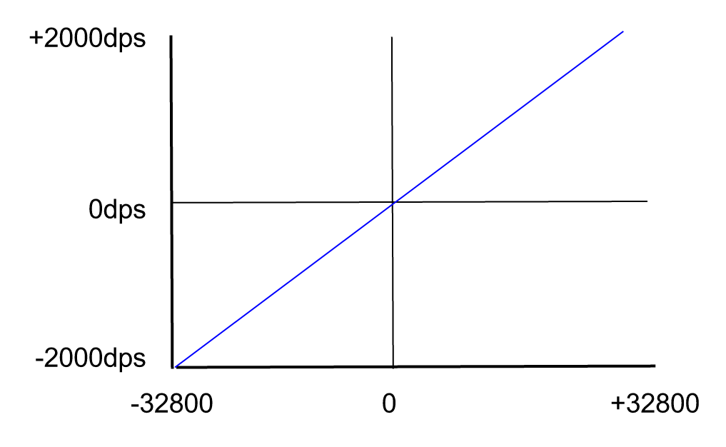
GYRO X/Y/Z
The following image depicts the direction of the Gyro axes of the OpenCR.
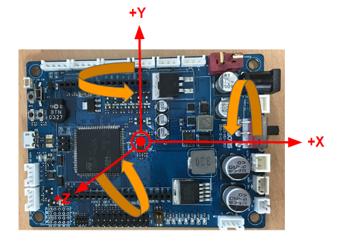
Each arrow represents the orientation of a gyroscope axis.
The data range is -2000dps ~ +2000dps.
The following graph shows the relation between actual data values and angular velocity value.
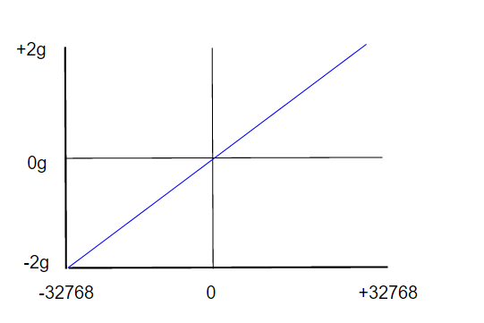
Acceleration X/Y/Z
The following picture represents the direction of the accelerometer axes of OpenCR.
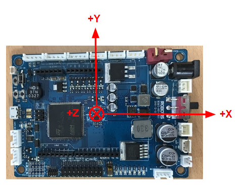
Each arrow represents the orientation of accelerometer axis.
The data range is -2g ~ +2g.
The following graph shows the relation between actual data value and acceleration value.
IMU_Control
This data controls the roll / pitch / yaw offset values for the IMU sensor.
| BIT | 7 ~ 4 | 3 | 2 | 1 | 0 |
|---|---|---|---|---|---|
| Value | X | Gyro | Yaw | Pitch | Roll |
For each bit set to 1, the corresponding roll, pitch, or yaw gyro values will be used for calculating the offset.
The calculation will take approximately 2 seconds and then each bit will be reset to 0.
GPIO Pin Assignments
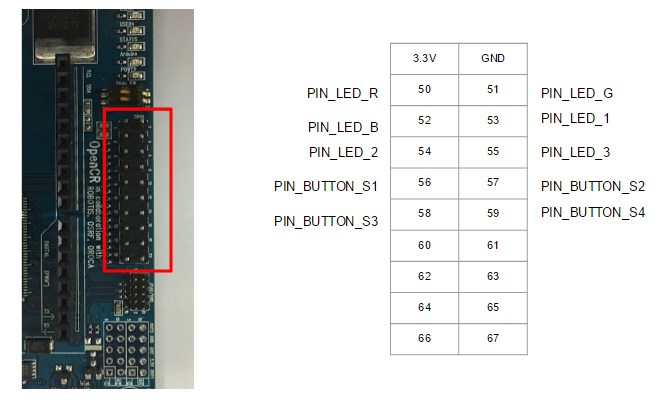
| Pin | Assignments |
|---|---|
| PIN_LED_R | Red LED pin |
| PIN_LED_G | Green LED pin |
| PIN_LED_B | Blue LED pin |
| PIN_LED_1 | LED output 1 |
| PIN_LED_2 | LED output 2 |
| PIN_LED_3 | LED output 3 |
| PIN_BUTTON_S1 | Button Input S1 |
| PIN_BUTTON_S2 | Button Input S2 |
| PIN_BUTTON_S3 | Button Input S3 |
| PIN_BUTTON_S4 | Button Input S4 (Reset DYNAMIXEL Power) |
Quick Start
Power On
The following procedure takes you through the set up process.
WARNING : Manually configuring ROBOTIS OP3’s ready pose other than the above pose may cause mechanical damages when posing for initial stance.
Connect the AC plug of the power adapter into a power outlet and plug the DC connector into ROBOTIS OP3’s DC jack. The DC jack is located on the back panel of ROBOTIS OP3.
You can select either the DC power supply or battery pack to power ROBOTIS OP3.
If you want to use the battery pack, please follow the below procedure.
- Ensure the battery pack is fully charged.
- Open the battery compartment door (unscrew the thumbscrew) and insert the battery pack.
- Connect the battery cable to the battery power jack.
- Close and secure the compartment door (screw the thumbscrew) afterwards.
- Disconnect DC power supply.
WARRNING : Please turn off the power switch before connecting power source(battery or SMPS) to the product.
WARNING : Make sure OpenCR should be switched off when connecting the battery.
Pushing the power switch to the right will power up the ROBOTIS OP3 (to the right : power on, to the left : power off)
Once Power is on, the following procedure will be sequentially executed.
Execute Demo Program
Running Demonstration Programs
ROBOTIS OP3 is loaded with the following pre-configured operation modes :
- Demonstration-Ready Mode
- Autonomous Soccer Mode
- Vision Processing Mode
- Interactive Motion Mode
Demonstration-Ready mode is set as a default mode when ROBOTIS OP3 is turned on.
Press MODE button to navigate the mode.
ROBOTIS OP3 will verbally announce the selected mode when pressing the button.
The indicating LED will also change its color to the corresponding operation mode.
Press START button to run the selected mode.
After pressing START ROBOTIS OP3 will stand up and begin operations.
RESET Button
The RESET button only resets actuators and the OpenCR sub-controller, not the entire system. Please keep in mind that the demo program is still running in the main controller when RESET button is pressed.
Pressing RESET button will disable torque on all actuator. It is highly recommended to set ROBOTIS OP3 for kneeling pose before pressing RESET button or hold ROBOTIS OP3 using its carrying handle.
Demonstration Ready Mode
The Demonstration-Ready mode is a default mode when ROBOTIS OP3 is turned on. LED 1 (red), LED 2 (green) and LED 3 (blue) will be lit.
The chest LED will switch the color from red to green while ROBOTIS OP3 verbally announces “Demonstration-ready mode”.
Now ROBOTIS OP3 is ready for action!
ROBOTIS OP3 stays in kneeling pose and does not move while in this mode.
This is the most recommended mode to change the power source.
Autonomous Soccer Mode
ROBOTIS OP3 follows and kicks a red ball (user can change the color of ball) and plays soccer by itself.
If ROBOTIS OP3 falls down (either on its back or belly) it will stand up and resume ball tracking, then pursuit.
- Start Autonomous Soccer Mode
-
Press
MODEbutton until LED1(red) is lit.
ROBOTIS OP3 will verbally announce “Autonomous soccer mode”. -
Press
STARTbutton to begin.
ROBOTIS OP3 will stand up and walk around to find the ball.ROBOTIS-OP3 will verbally announce “Start soccer demonstration” -
When ROBOTIS OP3 sees a ball with the matching color, it will walk toward the ball.
If ROBOTIS OP3 gets close enough to the ball, ROBOTIS OP3 will kick the ball with one of its feet.
If ROBOTIS OP3 falls down during pursuit or kick, it will stand up and resume.
-
- Stop Autonomous Soccer Mode
- Press
MODEbutton until LED 3(blue) is lit. ROBOTIS OP3 will verbally announce “Interactive motion mode”.
- Press
Interactive Motion Mode
ROBOTIS OP3 performs pre-programmed motions sequentially while talking.
- Start Interactive Motion Mode
-
Press
MODEbutton until LED 3(blue) is lit. ROBOTIS OP3 will verbally announce “Interactive motion mode”. - Press
STARTbutton to begin. ROBOTIS OP3 will stand up and announce “Start motion demonstration”. - ROBOTIS OP3 will perform following actions sequentially.
-
- Stop Interactive Motion Mode
- If
MODEbutton is pressed for at least 2 seconds, ROBOTIS-OP3 will return to demonstration-ready mode.
- If
Vision Processing Mode
The new vision processing demo for ROBOTIS OP3 is “Face detection and tracking”. ROBOTIS OP3 is developed with ROS.
Therefore various ROS packages such as face detecting package can be applied for vision processing mode to track recognized face in front of the robot.
Please refer the below website link.
Face detecting : https://github.com/phil333/face_detection
- Start Vision Processing Mode
-
Press
MODEbutton until LED 2(green) is lit. ROBOTIS OP3 will verbally announce “Vision processing mode”. - Press
STARTbutton to begin. ROBOTIS OP3 will verbally announce “Start vision processing demonstration” and stand up. - The target face should be located approximately 90cm(36”) away from ROBOTIS OP3.
If ROBOTIS OP3 detects the target face, chest LED will be lit in white whereas the LED will be off if ROBOTIS OP3 doesn’t detect the face.
ROBOTIS OP3 will keep track on the first recognized target face.
-
- Stop Vision Processing Mode
- If
MODEbutton is pressed for at least 2 seconds, ROBOTIS-OP3 will return to Demonstration-Ready mode.
- If
- ETC
- Modifying parameters of the ‘face_detection’ package might improve recognition of the face. Please refer to the following website for more details.
- face_detection package : https://github.com/ROBOTIS-GIT/face_detection
- usb_cam package : http://wiki.ros.org/usb_cam
Camera Calibration
If ambient light of ROBOTIS OP3 is either too dim or too bright, user can adjust camera setting for optimizing acquired image from the camera.
The color of the ball for soccer demo can also be modified from the setting.
Please refer to the wiki manual from below link.
ROBOTIS OP3 Camera Setting
Power Off
Please perform below procedures in order to shutdown the computer inside ROBOTIS OP3.
-
Press PC power button which is located on the belly. ROBOTIS OP3 will verbally announce “bye-bye” and initiate shutdown process.
When the internal computer of ROBOTIS OP3 is turned off, blue LED at the chest will be off.
After the blue LED is turned off, shutdown the main power with the switch in the back of the robot. -
If ROBOTIS OP3 does not announce “bye-bye” then you may need to force shutdown by holding the power button until the blue LED at the chest turns off.
NOTE : If power supply is cut off before the blue LED is turned off, ROBOTIS OP3 may have problems in the next startup.
Programming Guide
Connect to OP3
From your computer go to Wi-Fi Setting and set to obtain an IP address automatically using DHCP.
Then connect to ROBOTIS OP3 wifi network(SSID : ROBOTIS-OP3-share). Password is 11111111.
Example : SSH Client (for Windows)
- Execute SSH client program (ex: PuTTY)
- Input ROBOTIS OP3’s IP address:
10.42.0.1 - Select
SSHas a connection type and open the connection. - Input ROBOTIS OP3’s user name :
robotis - Input ROBOTIS OP3’s Password :
111111
Example: SSH Client (for Linux)
- Open the terminal window.
- Input the following SSH command with ROBOTIS OP3’s user name and IP address :
$ ssh robotis@10.42.0.1 - Input ROBOTIS OP3’s Password :
111111
Example: VNC client (for Windows)
- Users who are familiar to graphical interface may use remote desktop softwares.
- Execute VNC client program (ex: Ultra VNC Viewer)
- Input the ROBOTIS OP3’s IP address :
10.42.0.1 - Input the ROBOTIS OP3’s Password :
111111
Development Environment
The following is the list of tools for source code development.
- OS : Linux (64-bit)
- Compiler : GNU project C and C++ Compiler, Catkin
- Programming Language : C++
Source Code
You may find the source code directory at /robotis from ROBOTIS OP3’s PC.
The pre-installed source code may be updated without prior notice. Please check for updates periodically. You may obtain updated source code from the below GitHub links :
- https://github.com/ROBOTIS-GIT/DynamixelSDK
- https://github.com/ROBOTIS-GIT/ROBOTIS-Framework
- https://github.com/ROBOTIS-GIT/ROBOTIS-Framework-msgs
- https://github.com/ROBOTIS-GIT/ROBOTIS-Math
- https://github.com/ROBOTIS-GIT/ROBOTIS-OP3
- https://github.com/ROBOTIS-GIT/ROBOTIS-OP3-Common
- https://github.com/ROBOTIS-GIT/ROBOTIS-OP3-Demo
- https://github.com/ROBOTIS-GIT/ROBOTIS-OP3-msgs
- https://github.com/ROBOTIS-GIT/ROBOTIS-OP3-Tools
- https://github.com/ROBOTIS-GIT/ROBOTIS-Utility
Framework
The following flow diagram represent class breakdown and data pipelines.
You may modify the framework at “/home/robotis/catkin_ws/src/ROBOTIS-Framework”.
For more information, please refer to the WIKI.
ROBOTIS Framework WIKI
Software Utilities
User who wishes to customize or diagnose ROBOTIS OP3 should establish a connection with the robot via SSH or Remote Desktop(VNC). The tools are located in the following directory : home/robotis/catkin_ws/src/ROBOTIS-OP3/ROBOTIS-OP3-Tools
In the directory you can find code for :
Recovery Software
The supplied USB thumb drive contains the software pre-installed to ROBOTIS OP3.
You may obtain updated software from the link below.
ROBOTIS OP3 Recovery
Software may be updated without prior notice. Please check for updates periodically.
Useful Information
You can download other ROBOTIS OP3-related items and more detailed information from the wiki manual.
ROBOTIS OP3 Tutorial
- For any inquiries send us an email.
- International :
contactus2@robotis.com - Korea :
korea@robotis.com
- International :
- Third party terminal client
- PuTTY : http://www.chiark.greenend.org.uk/~sgtatham/putty/
- RealVNC : http://www.realvnc.com/
Miscellaneous
System Block Diagram
The below diagram illustrates the overall system structure of ROBOTIS OP3.
- Main Controller is powered by Intel i3 dual-core(Intel NUC i3)
- Sub Controller is powered by STMicroelectronics Cortex-M7 32F746GT6 (clocked at 216MHz).
- Camera
- 1080p Full HD movie recording
- Carl Zeiss® optics with 20-step autofocus
- Built-in dual stereo mics with noise reduction
- H.264 video encoding
ID Map
The following diagram illustrates the default ID number of actuators in ROBOTIS OP3.
ROBOTIS-OP3 Revision
Based on the type of internal PC, ROBOTIS-OP3 will be revised accordingly.
Warranty
ROBOTIS OP3 includes the following warranty:
A. 90 days warranty against manufacture defects (RMA required) *
B. Local Maintenance Service (by local partner) : 1 years **
- Re-installation of S/W and firmware
- Replacement for cable/gear/screw (RMA required – exempt from faulty return)
- Replacement for faulty frame/cover/actuator (RMA required)
C. Core System Maintenance Service (by ROBOTIS) : 1 years
- Replacement for faulty PC/sub-boards (RMA required)
- Maintenance for actuator/sub-boards (RMA required)
- Maintenance for PC (RMA required, additional fee applies)
D. Parts replacement for malfunctions during normal operation for 1 years.
* Please download RMA (Return Material Authorization)(http://en.robotis.com/index/service_04.php?tab=4)
No return shipping will be accepted without a RMA number issued by ROBOTIS.
** Customers who require extended warranty period may purchase another “1 year warranty” from ROBOTIS before their standard warranty period is over.
Important Notice:
-
Product registration is required for all customers. http://support.robotis.com
-
Parts replacement can only be done through RMA(Return Material Authorization) application.
-
After the initial 90 days, shipping fee is not covered under warranty.
- Warranty does NOT cover ordinary wear/tear, any accident or damage caused by followings.
- Physical damage equivalent to dropping the robot from 20cm or higher
- Disabling system safety function (DYNAMIXEL Overload Shutdown)
- Dangerous movement (jump, roll, fi ght) or excessive operation without rest
- Any liquid or unauthorized chemical material to the robot
- Unauthorized power or electric shock applied to the robot
- Improvising core system programming area.
- Direct check-up service
Evaluation, maintenance and quality assurance of assembled robot can be provided by ROBOTIS only.
RMA is required and additional fee may apply. Service will not be rendered for seriously customized hardware.
Sub Controller(OpenCR)
WARRNING : Please turn off the power switch before connecting power source(battery or SMPS) to the product.
Control Table
Control Table consists of data regarding the current status and operation of OpenCR. The user can control OpenCR by changing data of Control Table via Instruction packet.
EEPROM and RAM
Data in RAM area is reset to initial values whenever the power is turned on while data in EEPROM area is kept once values are set even if the power is turned off.
Address
Represents the location of data. To read from or write data to the control table the user should assign the correct address in the Instruction packet.
Access
OpenCR has two kinds of data: Read-only data, used mainly for sensing, and read-and-write data used for driving.
Initial Value
In case of data in the EEPROM Area, the initial values on the right side of the below Control Table are the factory default settings.
In case of data in the RAM Area, the initial values on the right side of the following control table are the ones when the power is turned on.
Highest/Lowest Byte
In the Control table, some data share the same name, but they are attached with (L) or (H) at the end of each name to distinguish the address. This data requires 16-bit, but it is divided into 8bit each for the addresses (low) and (high). These two addresses should be written with one Instruction Packet simutaneously.
EEPROM Area
| Address | Name | Description | Access | Init Value |
|---|---|---|---|---|
| 0 (0X00) | Model Number(L) | model number low byte | R | 0(0X00) |
| 1 (0X01) | Model Number(H) | model number high byte | R | 116 (0X74) |
| 2 (0X02) | Version of Firmware | firmware version | R | - |
| 3 (0X03) | ID | OpenCR ID | RW | 200 (0XC8) |
| 4 (0X04) | Baud Rate | Communication baud rate | RW | 1 (0X01) |
| 5 (0X05) | Return Delay Time | Return Delay Time | RW | 0 (0X0) |
| 16 (0X10) | Status Return Level | Status Return Level | RW | 0 (0X00) |
RAM Area
| Address | Name | Description | Access | Init Value |
|---|---|---|---|---|
| 24 (0X18) | DYNAMIXEL Power | DYNAMIXEL On/Off | RW | 0 (0X00) |
| 25 (0X19) | LED | LED Pannel On/Off | RW | 0 (0X00) |
| 26 (0X1A) | LED_RGB(L) | LED 5 low byte | RW | 0 (0X00) |
| 27 (0X1B) | LED_RGB(H) | LED 5 high byte | RW | 0 (0X00) |
| 28 (0X1C) | Buzzer(L) | LED 6 low byte | RW | 0 (0X00) |
| 29 (0X1D) | Buzzer(H) | LED 6 high byte | RW | 0 (0X00) |
| 30 (0X1E) | Button | Button status | R | - |
| 31 (0X1F) | Voltage | Power Voltage | R | - |
| 32 (0X20) | Gyro_Z(L) | Gyroscope Z-axis low byte | R | - |
| 33 (0X21) | Gyro_Z(H) | Gyroscope Z-axis high byte | R | - |
| 34 (0X22) | Gyro_Y(L) | Gyroscope Y-axis low byte | R | - |
| 35 (0X23) | Gyro_Y(H) | Gyroscope Y-axis high byte | R | - |
| 36 (0X24) | Gyro_X(L) | Gyroscope X-axis low byte | R | - |
| 37 (0X25) | Gyro_X(H) | Gyroscope X-axis high byte | R | - |
| 38 (0X26) | ACC_X(L) | Accelerometer X-axis low byte | R | - |
| 39 (0X27) | ACC_X(H) | Accelerometer X-axis high byte | R | - |
| 40 (0X28) | ACC_Y(L) | Accelerometer Y-axis low byte | R | - |
| 41 (0X29) | ACC_Y(H) | Accelerometer Y-axis high byte | R | - |
| 42 (0X2A) | ACC_Z(L) | Accelerometer Z-axis low byte | R | - |
| 43 (0X2B) | ACC_Z(H) | Accelerometer Z-axis high byte | R | - |
| 44 (0X2C) | Roll(L) | IMU Roll low byte | R | - |
| 45 (0X2D) | Roll(H) | IMU Roll high byte | R | - |
| 46 (0X2E) | Pitch(L) | IMU Pitch low byte | R | - |
| 47 (0X2F) | Pitch(H) | IMU Pitch high byte | R | - |
| 48 (0X30) | Yaw(L) | IMU Yaw low byte | R | - |
| 49 (0x31) | Yaw(H) | IMU Yaw high byte | R | - |
| 50 (0X32) | IMU_Control | IMU Control | RW | 0x00 |
Address Function Help
Model Number
Represents the Model Number.
Firmware Version
Represents the firmware version.
ID
Is a unique number to identify DYNAMIXEL.
Values range from 0 (0x00) to 252 (0xFC), Value 254 (0xFE) is used as the Broadcast ID.
If the Broadcast ID is used to transmit Instruction Packet, then it can command to all DYNAMIXEL.
NOTE : Do NOT assign an identical ID for DYNAMIXEL in the same network.
Baud Rate
Represents the communication speed. 0 (0x00) to 7 (0x07) can be used for it.
| Data | Set BPS | Target BPS | Tolerance |
|---|---|---|---|
| 0 | 9,600 | 9,600 | 0.000 % |
| 1 | 57,600 | 57,600 | 0.000 % |
| 2 | 115,200 | 115,200 | 0.000 % |
| 3 | 1,000,000 | 1,000,000 | 0.000 % |
| 4 | 2,000,000 | 2,000,000 | 0.000 % |
| 5 | 3,000,000 | 3,000,000 | 0.000 % |
| 6 | 4,000,000 | 4,000,000 | 0.000 % |
| 7 | 4,500,000 | 4,500,000 | 0.000 % |
NOTE : Maximum Baud Rate error of 3% is within the tolerance of UART communication.
Return Delay Time
Return Delay Time will set a timer to hold a Status Packet transmission for a received Instruction Packet.
This data has a multiplier of 2μsec, therefore set value will be multiplied by 2 microseconds.
For example, if Return Delay Time is set to 10, a Status Packet will be transmitted after 20 microseconds after receiving an Instruction Packet.
Available data values range from 0 (0x00) to 254 (0xFE).
Status Return Level
Status Return Level decides whether to return a Status Packet or not for an Instruction Packet.
There are three options as below table.
If an Instruction Packet has a Broadcast ID, Status Packet will not be returned regardless of Status Return Level.
| Value | Return of Status Packet |
|---|---|
| 0 | No return against all commands (Except PING Command) |
| 1 | Return only for the READ command |
| 2 | Return for all commands |
NOTE : When Instruction packet is Broadcast ID, Status packet is not returned regardless of Status return level.
DYNAMIXEL Power
| Value | Meaning |
|---|---|
| 0 | Turn off the power of all DYNAMIXEL connected to OpenCR. |
| 1 | Turn on the power of all DYNAMIXEL connected to OpenCR. |
LED Pannel
| BIT | 7 ~ 3 | 2 | 1 | 0 |
|---|---|---|---|---|
| Value | X | LED3 | LED2 | LED1 |
For each set bit, corresponding LED will be turned on.
For each reset bit, corresponding LED will be turned off.
LED_RGB
| BIT | 15 | 14 ~ 10 | 9 ~ 5 | 4 ~ 0 |
|---|---|---|---|---|
| Value | X | LED_B | LED_G | LED_R |
Chest LED is a tricolor LED and the color can be represented with RGB values.
Buzzer
| Value | Description |
|---|---|
| 0 ~ 65535 | Frequency(Hz) of Buzzer |
If the Buzzer value is set to 0, the buzzer will be turned off.
BUTTON STATUS
| BIT | 7 ~ 4 | 3 | 2 | 1 | 0 |
|---|---|---|---|---|---|
| Value | X | BUTTON_S4 | BUTTON_S3 | BUTTON_S2 | BUTTON_S1 |
For each bit set to 1, the button is being pressed.
For each bit set to 0, the button is released.
VOLTAGE
This value stands for the input voltage of the controller with a multiplier of 10.
For example, when 10V is supplied to the controller, the Voltage value will be 100.
GYRO X/Y/Z
The following image represents the direction of Gyro axis of OpenCR.
Each arrow represents the orientation of gyroscope axis.
The data range is -2000dps ~ +2000dps.
The following graph shows relation between actual data value and angular velocity value.
Acceleration X/Y/Z
The following picture represents the direction of accelerometer axis of OpenCR.
Each arrow represents the orientation of accelerometer axis.
The data range is -2g ~ +2g.
The following graph shows relation between actual data value and acceleration value.
IMU_Control
This data controls roll / pitch / yaw offset values for the IMU sensor.
| BIT | 7 ~ 4 | 3 | 2 | 1 | 0 |
|---|---|---|---|---|---|
| Value | X | Gyro | Yaw | Pitch | Roll |
For each bit set to 1, corresponding roll, pitch, yaw, gyro values will be used for calculating offset values.
The calculation will take for 2 seconds and then each bit will be reset to 0.
GPIO Pin Assignments
| Pin | Assignments |
|---|---|
| PIN_LED_R | Red LED pin |
| PIN_LED_G | Green LED pin |
| PIN_LED_B | Blue LED pin |
| PIN_LED_1 | LED output 1 |
| PIN_LED_2 | LED output 2 |
| PIN_LED_3 | LED output 3 |
| PIN_BUTTON_S1 | Button Input S1 |
| PIN_BUTTON_S2 | Button Input S2 |
| PIN_BUTTON_S3 | Button Input S3 |
| PIN_BUTTON_S4 | Button Input S4 (Reset DYNAMIXEL Power) |