Getting Started
Prerequisite
- Allow sufficient workspace prior to setup by clearing objects in the arm’s vicinity.
- Always ensure the Manipulator is properly fixed to the base plate prior to operations; otherwise arm movements can cause damage and physical injury.
- Supply power to the Manipulator after making sure all cables are properly connected. While powered on do not touch the cables as it may cause erroneous operations or/and damage.
- When handling the Manipulator do so carefully as not to have your fingers stuck in the frames.
- If the Manipulator operates erroneously quickly cut off power by turning the power supply off.
- While the Manipulator is in operation keep out of its workspace; ensure no objects enter the workspace during operations.
Preparation
Power Supply
The Manipulator requires 24V for operations. Ensure the power supply is capable of supplying 24V and 15A or higher.
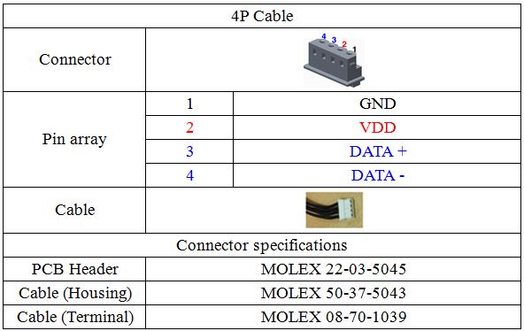
4P Cable
The 4P Cable connects the Manipulator and USB2DYNAMIXEL.
Power Cable
The power cable supplies power to the Manipulator.
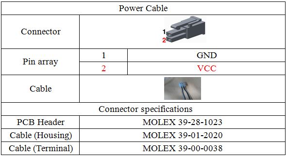
For additional power or 4P cables contact ROBOTIS or obtain them with the specifications listed above.
USB2DYNAMIXEL
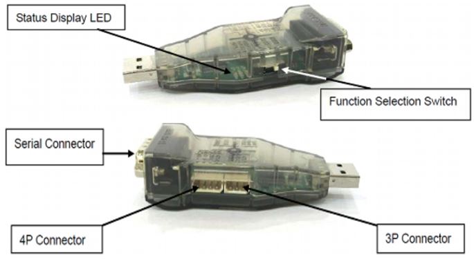
The USB2DYNAMIXEL sends ArmSDK commands to the Manipulator. Connect the USB2DYNAMIXEL to the PC via USB hub.
Product Assembly
NOTE : The content below is based on an optional base plate and differs from the actual base plate.
- Rest and fix joint 1 of the Manipulator.
-
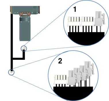
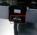
The photo on the left is the external wiring for the arm. Label “1” shows a pair of 4P cables and power connector; these connect to joint 1 as shown on the right picture.
-
Label “2” shows a 4P connector and 4 power connectors and these connect to the power expansion hub and the 4P cable connects to the extension.
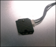
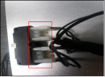
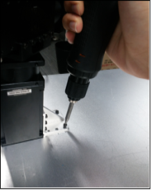
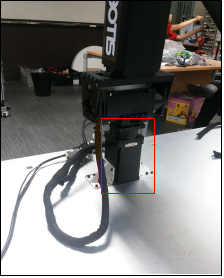
- Once connections are complete fix the arm to the base plate as shown on the photo above. The joint fixed to the plate is joint 1.
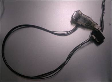
- Connect USB2DYNAMIXEL to the hub with 4P cable; connect another port of the 4P hub to the extension.
CAUTION : Connect the USB2DYNAMIXEL to the PC via USB hub. The USB hub acts as an isolator to protect the PC from any possible unexpected surges caused by arm action.
USB2DYNAMIXEL Setting

| Communication | Description |
|---|---|
| TTL | AX, 3-pin MX; communicate with 3-pin DYNAMIXEL |
| RS485 | RX, 4-pin MX and Pro; communicate with 4-pin DYNAMIXEL |
| RS232 | CM-5, CM-510; communicate with these controllers. Communicate with other RS-232 devices |
NOTE : The manipulator is based on RS-485 communications so make sure to set the dongle to 485.
Manipulator Test
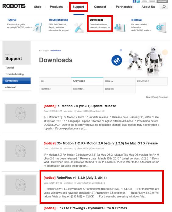
- Test the arm with DYNAMIXEL Wizard to check for any anomalies. DYNAMIXELWizard is included in RoboPlus suite. RoboPlus can be downloaded from ROBOTIS home page’s Support -> Downloads(http://www.robotis.com/xe/download).
CAUTION : Do NOT download RoboPlus v2.0. Use RoboPlus v1.0 for Manipulator-H.
-
Install and run RoboPlus; click on DYNAMIXEL Wizard button to start DYNAMIXEL Wizard.
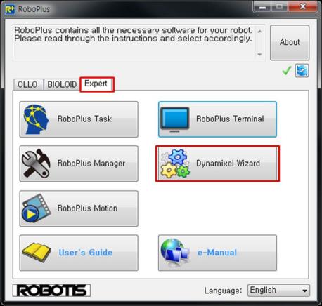
Operating the Manipulator
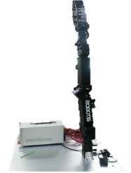
DANGER : Before starting DYNAMIXEL Wizard ensure the arm is fixed to the base plate; then extend the arm. Otherwise; it may cause physical harm.
-
USB2DYNAMIXEL to the PC after wiring is complete. From the PC check the COM port number of USB2DYNAMIXEL.
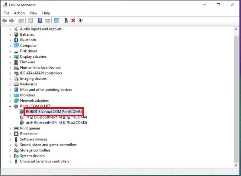
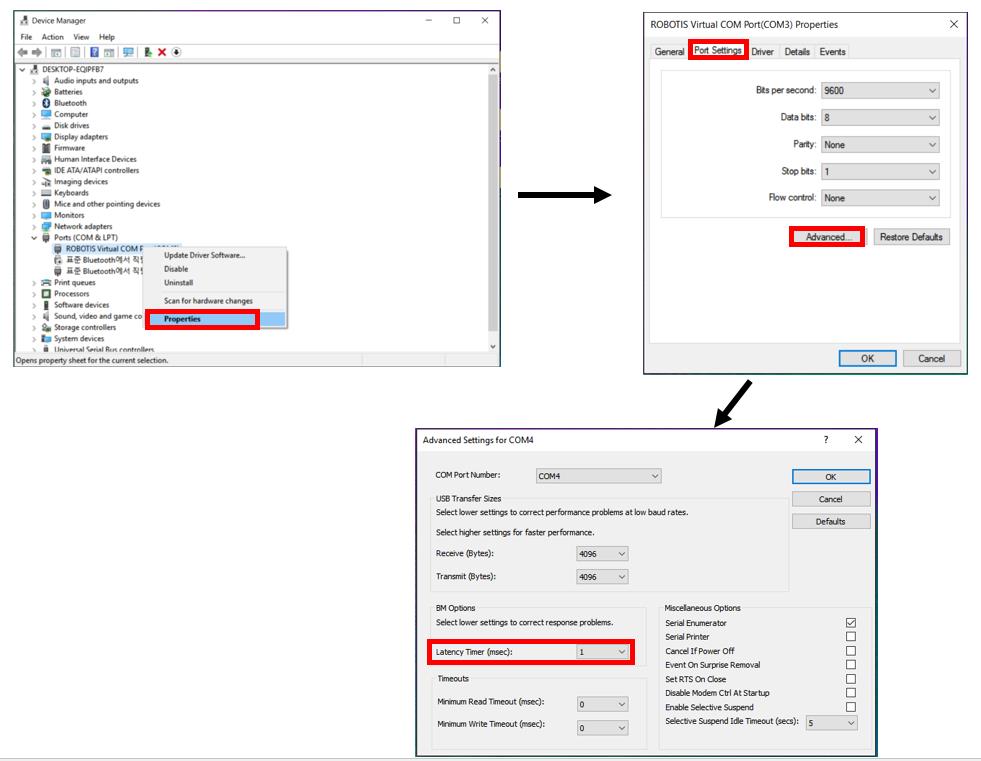
- Select the Port Settings tab and click on the Advanced button-> change the latency time from 16 (default) to 1.
- After changing the COM port settings supply the 24V to the arm (of course, this means wiring is complete).
CAUTION : Always ensure before powering on. While power is on do not change wires; otherwise it may cause undesired operations.
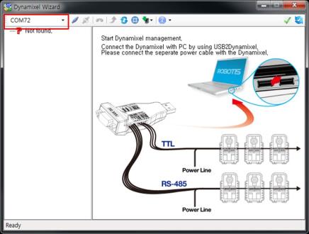
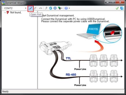
-
The picture on the left is the COM port number of USB2DYNAMIXEL (which should be connected to the arm). Click on the to continue
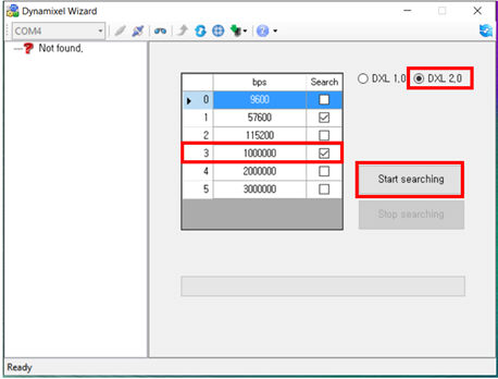
-
Once connected make sure that 1000000bps box is checked and “DXL 2.0” is selected. Then click on Search. The arm’s default baud rate is 1 Mbps.
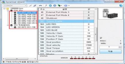
-
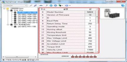
Once search is complete the arm’s components (DYNAMIXEL PROs) are listed on the left. Click on an individual DYNAMIXEL PRO to display the contents of its Control Table.
-
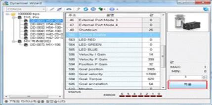
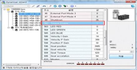
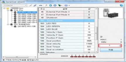
DYNAMIXEL Pro will only move (operate) when Torque Mode is on. So always make sure the Torque Mode is on prior to sending moving commands.
Torque Enable is located on address number 562. A value of 1 means on and 0 means off.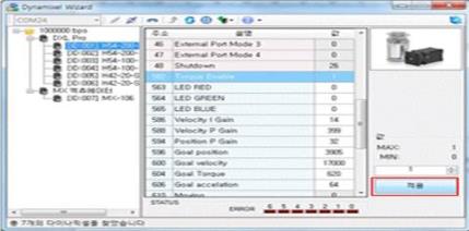
-
Turn ‘Torque Enable’ on to all joints. The pose of the arm will become rigid (check by applying a small force). Afterwards click on joint 6.
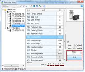
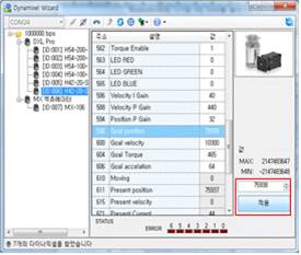
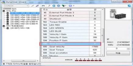
- Now verify the arm moves properly by changing Goal Position. Move the end effector (joint 6) +90 degrees.
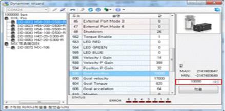
To move joint 6 to +90 degrees set Goal Position of DYNAMIXEL PRO model H42-20-S300-R to 75938 or L42-10-S300-R to 1024. - Once Goal Position has been set visually verify that joint 6 has rotated 90 degrees.
- To actually get DYNAMIXEL PRO to move to its respective Goal Position, click on the Apply button after setting the value. If there is no movement, make sure Torque Enable is turned on (set to 1).
-
Set Goal Position back to 0 to set position to its original position.
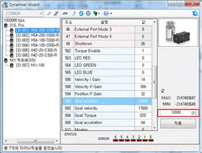
- Click on ID. Set the Goal Position to 1000 (500 for L42 model).
- To actually get DYNAMIXEL PRO to move to its respective Goal Position, click on the Apply button after setting the value. If there is no movement, make sure Torque Enable is turned on (set to 1).
- Set Goal Position back to 0 to set position to its original position..
- Do the same procedure for joint 2 through 6.
Goal Position Values with Respect to Rotation
- Goal Position value determines the rotational position of DYNAMIXEL PRO.
| Model Name | Relationship between angle(deg) and position value |
|---|---|
| H54-200-S500-R H54-100-S500-R |
-180 ~ 180 (deg) → -251000 ~ 251000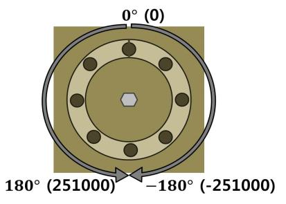  |
| H42-20-S300-R | -180 ~ 180 (deg) → -151875 ~ 151875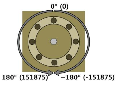  |
| L54-50-S500-R | -180 ~ 180 (deg) → -125700 ~ 125700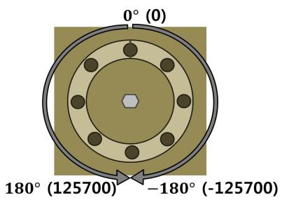  |
| L54-30-S500-R | -180 ~ 180 (deg) → -144180 ~ 144180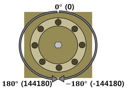  |
| L42-20-S300-R | -180 ~ 180 (deg) → -2048 ~ 2048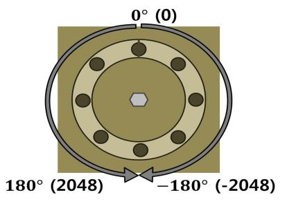  |


