
Specification
Hardware Specification
| Items | Unit | OpenMANIPULATOR-X |
|---|---|---|
| Actuator | DYNAMIXEL XM430-W350-T | |
| Input Voltage | V | 12 |
| DOF | - | 5 (4 DOF + 1 DOF Gripper) |
| Payload | g | 500 |
| Repeatability | mm | < 0.2 |
| Speed(Joint) | RPM | 46 |
| Weight | kg (lb) | 0.70 (1.54) |
| Reach | mm (in) | 380 (14.9) |
| Gripper Stroke | mm (in) | 20~75 (0.79~2.95) |
| Communication | - | TTL Level Multidrop BUS |
| Software | - | ROS, DYNAMIXEL SDK, Arduino, Processing |
| Main Controller | - | PC, OpenCR |
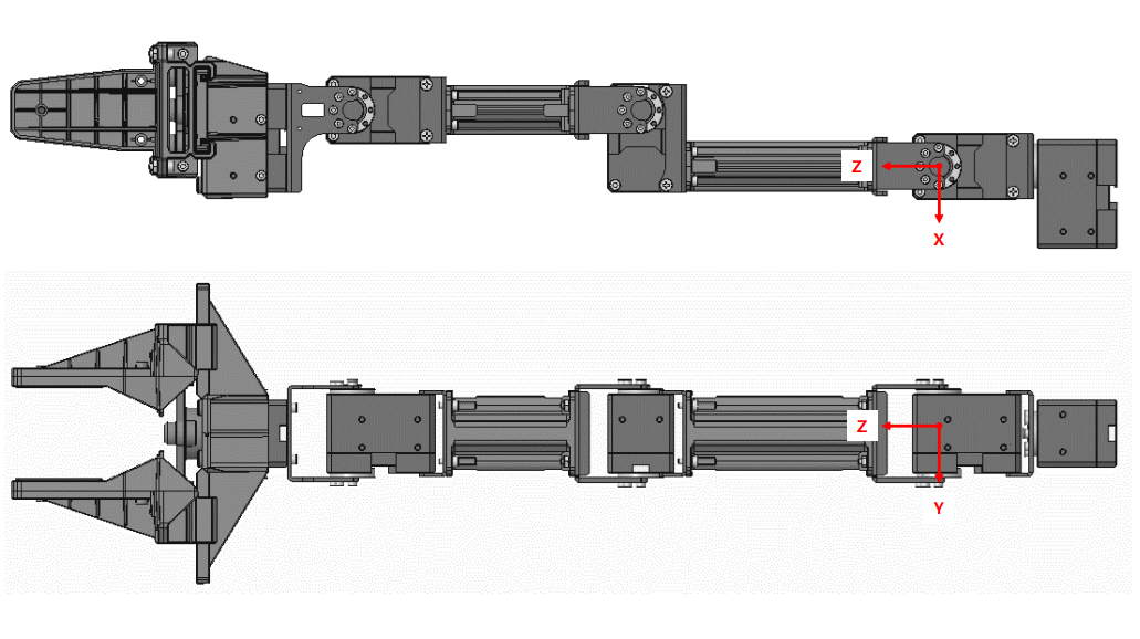
Dimension
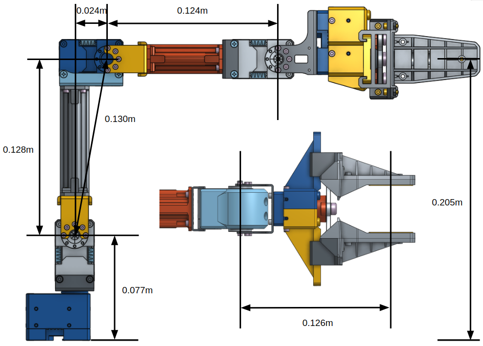
Inertia
Total Mass : 711.37 gram
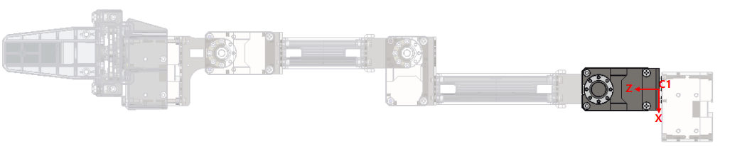
Joint 1
- Mass [gram] : 1.0483260e+02
- Center of Gravity [mm]
- X : 0.0000000e+00
- Y : -5.6914372e-01
- Z : 2.6565513e+01
- Inertia Tensor with respect to C1 coordinate frame: [GRAM * MM^2]
- Ixx Ixy Ixz : 1.0781918e+05 0.0000000e+00 0.0000000e+00
- Iyx Iyy Iyz : 0.0000000e+00 1.0355255e+05 1.8062416e+03
- Izx Izy Izz : 0.0000000e+00 1.8062416e+03 1.7644210e+04
- Inertia Tensor at CENTER OF GRAVITY with respect to coordinate frame: [GRAM * MM^2]
- Ixx Ixy Ixz : 3.3802078e+04 0.0000000e+00 0.0000000e+00
- Iyx Iyy Iyz : 0.0000000e+00 2.9569411e+04 2.2121514e+02
- Izx Izy Izz : 0.0000000e+00 2.2121514e+02 1.7610252e+04
- Principal Moments of Inertia: [GRAM * MM^2]
- I1 : 1.7606162e+04
- I2 : 2.9573501e+04
- I3 : 3.3802078e+04
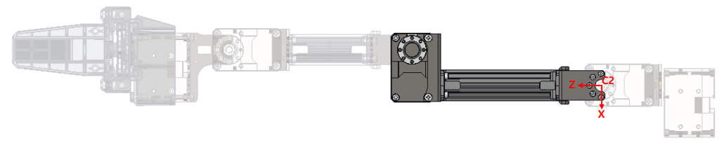
Joint 2
- Mass [gram] : 1.4234630e+02
- Center of Gravity [mm]
- X : -9.1617228e+00
- Y : -4.1915210e-01
- Z : 1.0599936e+02
- Inertia Tensor with respect to C2 coordinate frame: [GRAM * MM^2]
- Ixx Ixy Ixz : 1.8365231e+06 -8.2177190e+02 1.6490470e+05
- Iyx Iyy Iyz : -8.2177190e+02 1.8562153e+06 7.6370887e+03
- Izx Izy Izz : 1.6490470e+05 7.6370887e+03 5.4940213e+04
- Inertia Tensor at CENTER OF GRAVITY with respect to coordinate frame: [GRAM * MM^2]
- Ixx Ixy Ixz : 2.3711450e+05 -2.7513999e+02 2.6666982e+04
- Iyx Iyy Iyz : -2.7513999e+02 2.4488355e+05 1.3126636e+03
- Izx Izy Izz : 2.6666982e+04 1.3126636e+03 4.2967059e+04
- Principal Moments of Inertia: [GRAM * MM^2]
- I1 : 3.9362142e+04
- I2 : 2.4070845e+05
- I3 : 2.4489452e+05
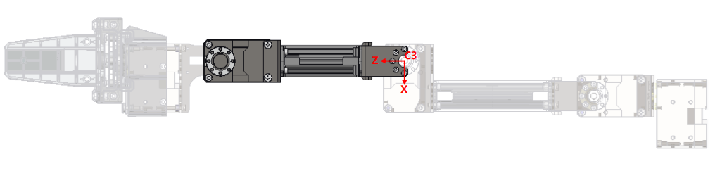
Joint 3
- Mass [gram] : 1.3467049e+02
- Center of Gravity [mm]
- X : 3.6312773e-04
- Y : -4.4304274e-01
- Z : 9.3290225e+01
- Inertia Tensor with respect to C3 coordinate frame: [GRAM * MM^2]
- Ixx Ixy Ixz : 1.3589608e+06 0.0000000e+00 -2.7331036e+00
- Iyx Iyy Iyz : 0.0000000e+00 1.3502276e+06 6.7882502e+03
- Izx Izy Izz : -2.7331036e+00 6.7882502e+03 2.4835638e+04
- Inertia Tensor at CENTER OF GRAVITY with respect to coordinate frame: [GRAM * MM^2]
- Ixx Ixy Ixz : 1.8688812e+05 0.0000000e+00 1.8290300e+00
- Iyx Iyy Iyz : 0.0000000e+00 1.7818139e+05 1.2221090e+03
- Izx Izy Izz : 1.8290300e+00 1.2221090e+03 2.4809204e+04
- Principal Moments of Inertia: [GRAM * MM^2]
- I1 : 2.4799466e+04
- I2 : 1.7819113e+05
- I3 : 1.8688812e+05
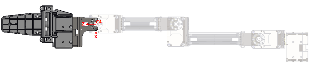
Joint 4
- Mass [gram] : 2.3550927e+02
- Center of Gravity [mm]
- X : 6.1273313e+00
- Y : 7.9503949e-04
- Z : 6.0472935e+01
- Inertia Tensor with respect to C4 coordinate frame: [GRAM * MM^2]
- Ixx Ixy Ixz : 1.1283350e+06 2.2172215e+02 -6.4649200e+04
- Iyx Iyy Iyz : 2.2172215e+02 1.0777914e+06 3.9825896e+00
- Izx Izy Izz : -6.4649200e+04 3.9825896e+00 1.8277436e+05
- Inertia Tensor at CENTER OF GRAVITY with respect to coordinate frame: [GRAM * MM^2]
- Ixx Ixy Ixz : 2.6708326e+05 2.2286943e+02 2.2615865e+04
- Iyx Iyy Iyz : 2.2286943e+02 2.0769766e+05 1.5305492e+01
- Izx Izy Izz : 2.2615865e+04 1.5305492e+01 1.7393236e+05
- Principal Moments of Inertia: [GRAM * MM^2]
- I1 : 1.6873182e+05
- I2 : 2.0769694e+05
- I3 : 2.7228452e+05
Understanding URDF
Understanding URDF (Universal Robot Description Format) with OpenManipulator-X
What is URDF?
URDF (Universal Robot Description Format) is an XML-based format used to describe a robot’s physical structure, kinematics, dynamics, and visualization properties. It is widely used in ROS (Robot Operating System) to define robot models for simulation, motion planning, and visualization.
URDF defines a robot using the following key elements:
- Links: Define a robot’s visual representation, collision geometry, and inertial properties.
- Joints: Define the connections and movement constraints between links.
- Visuals: Describe how the robot appears in visualization tools.
- Collisions: Define simplified geometries used for physics-based interactions.
- Inertial properties: Specify mass, center of gravity, and inertia tensor for physics simulation.
For a more detailed understanding of URDF, we recommend referring to the URDF Tutorial on the ROS 2 Wiki. The best way to understand and learn URDF is to build a simple robot yourself.
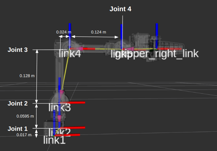
Visualizing the OpenManipulator-X URDF Structure
Understanding the hierarchical structure of the OpenManipulator-X is crucial before diving into the URDF breakdown. The following URDF graph visually represents the parent-child relationships between links and joints.

Key Features of the URDF Graph
- Root Node(world):
- The robot is fixed to the world frame via world_fixed.
- Link Structure:(Represent the rigid bodies of the robot)
- The manipulator consists of five main links (link1 to link5), which form the robotic arm.
- The end-effector (end_effector_link) is attached to link5.
- The gripper mechanism includes gripper_left_link and gripper_right_link.
- Joint Connections: (Define how each link moves relative to another)
- Each link is connected via revolute (joint1 to joint4) or prismatic joints (gripper_left_joint, gripper_right_joint).
- The gripper operates with a mimic joint (gripper_right_joint_mimic), ensuring both fingers move symmetrically.
The following image shows the OpenManipulator-X URDF model as visualized in RViz. It includes the joint positions and link dimensions, providing a clear representation of the robot’s structure.
URDF with Xacro
The provided URDF uses Xacro (XML Macros) to simplify and modularize the robot description. Xacro allows reusing components and making the URDF more maintainable.
The following explanation is based on the Xacro file:
open_manipulator/open_manipulator_x_description/urdf/open_manipulator_x.urdf.xacro
At the beginning of the file, a macro is defined:
<xacro:macro name="open_manipulator_x" params="prefix=''">
This allows the reuse of the same structure with different prefixes, making it flexible for multi-robot environments.
Defining a Link
A link represents a rigid body in the robot. Each link has visual, collision, and inertial properties.
Example of link1 in OpenManipulator-X:
<link name="${prefix}link1">
  <visual>
    <origin xyz="0 0 0" rpy="0 0 0"/>
    <geometry>
      <mesh filename="${meshes_file_direction}/link1.stl" scale="0.001 0.001 0.001"/>
    </geometry>
    <material name="grey"/>
  </visual>

  <collision>
    <origin xyz="0 0 0" rpy="0 0 0"/>
    <geometry>
      <mesh filename="${meshes_file_direction}/link1.stl" scale="0.001 0.001 0.001"/>
    </geometry>
  </collision>

  <inertial>
    <origin xyz="3.0876154e-04 0.0000000e+00 -1.2176461e-04" />
    <mass value="7.9119962e-02" />
    <inertia ixx="1.2505234e-05" ixy="0.0" ixz="-1.7855208e-07"
             iyy="2.1898364e-05" iyz="0.0"
             izz="1.9267361e-05" />
  </inertial>
</link>
Explanation
<visual>: Defines how the link appears in a simulation or visualization tool (e.g., RViz) using a 3D mesh (link1.stl).<collision>: Specifies the simplified geometry used for physics-based interactions (e.g., collisions).<inertial>: Defines the mass, center of gravity, and inertia tensor, which are crucial for realistic physics simulations.
Defining a Joint
A joint connects two links and defines how they move relative to each other.
Example of joint1 in OpenManipulator-X:
<joint name="${prefix}joint1" type="revolute">
  <parent link="${prefix}link1"/>
  <child link="${prefix}link2"/>
  <origin xyz="0.012 0.0 0.017" rpy="0 0 0"/>
  <axis xyz="0 0 1"/>
  <limit velocity="4.8" effort="1" lower="${-pi}" upper="${pi}" />
  <dynamics damping="0.1"/>
</joint>
Explanation
type="revolute": Defines a rotating joint (common in robotic arms).<parent>and<child>: Specifies the two links connected by the joint.<origin>: Defines the joint’s position relative to the parent link.<axis>: Specifies the rotation axis (0 0 1means rotation around the Z-axis).<limit>: Defines movement constraints (speed, torque, and range).<dynamics>: Includes damping, which affects how smoothly the joint moves.
Adding a Prismatic Joint
Prismatic joints allow linear motion rather than rotation.
Example from OpenManipulator-X gripper:
<joint name="${prefix}gripper_left_joint" type="prismatic">
  <parent link="${prefix}link5"/>
  <child link="${prefix}gripper_left_link"/>
  <origin xyz="0.0817 0.021 0.0" rpy="0 0 0"/>
  <axis xyz="0 1 0"/>
  <limit velocity="4.8" effort="1" lower="-0.010" upper="0.019" />
  <dynamics damping="0.1"/>
</joint>
Explanation
type="prismatic": Allows linear motion along the defined axis.<limit>: Restricts the movement range (from -0.010m to 0.019m).- Used for: The gripper’s movement (opening and closing).
Using a Fixed Joint
Fixed joints are used when a link does not move relative to another.
Example:
<joint name="${prefix}end_effector_joint" type="fixed">
  <parent link="${prefix}link5"/>
  <child link="${prefix}end_effector_link"/>
  <origin xyz="0.126 0.0 0.0" rpy="0 0 0"/>
</joint>
Explanation
type="fixed": No relative motion between links.- Used for: End-effectors or components that do not move.