
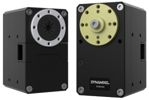
XH540-W270-T/R
Specifications
| Item | Specifications |
|---|---|
| MCU | ARM CORTEX-M3 (72 [MHz], 32Bit) |
| Position Sensor | Contactless absolute encoder (12Bit, 360 [°]) Maker : ams(www.ams.com), Part No : AS5045 |
| Motor | Coreless(Maxon) |
| Baud Rate | 9,600 [bps] ~ 4.5 [Mbps] |
| Control Algorithm | PID control |
| Resolution | 4096 [pulse/rev] |
| Backlash | 15 [arcmin] (0.25 [°]) |
| Operating Modes | Current Control Mode Velocity Control Mode Position Control Mode (0 ~ 360 [°]) Extended Position Control Mode (Multi-turn) Current-based Position Control Mode PWM Control Mode (Voltage Control Mode) |
| Weight | 165 [g] |
| Dimensions (W x H x D) | 33.5 x 58.5 x 44 [mm] |
| Gear Ratio | 272.5 : 1 |
| Stall Torque | 9.2 [N.m] (at 11.1 [V], 4.5 [A]) 9.9 [N.m] (at 12.0 [V], 4.9 [A]) 11.7 [N.m] (at 14.8 [V], 5.9 [A]) |
| No Load Speed | 36 [rev/min] (at 11.1 [V]) 39 [rev/min] (at 12.0 [V]) 46 [rev/min] (at 14.8 [V]) |
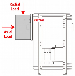
| Radial Load | 40 [N] (10 [mm] away from the horn) |
| Axial Load | 20 [N] |
| Operating Temperature | -5 ~ +80 [°C] |
| Input Voltage | 10.0 ~ 14.8 [V] (Recommended : 12.0 [V]) |
| Command Signal | Digital Packet |
| Physical Connection | RS-485 / TTL Multidrop Bus TTL Half Duplex Asynchronous Serial Communication with 8bit, 1stop, No Parity RS-485 Asynchronous Serial Communication with 8bit, 1stop, No Parity |
| ID | 253 ID (0 ~ 252) |
| Feedback | Position, Velocity, Current, Realtime tick, Trajectory, Temperature, Input Voltage, etc |
| Case Material | Metal (Front, Middle), Engineering Plastic (Back) |
| Gear Material | Full Metal Gear |
| Standby Current | 40 [mA] |
![]()
DANGER
(Ignoring these warnings may cause serious injury or death)
- Never place items containing water, flammables/open flames, or solvents near the product.
- Never place fingers, arms, toes, and other body parts near product during operation.
- Cease operation and remove power from the product if the product begins to emit strange odors, noises, or smoke.
- Keep product out of reach of children.
- Check input polarity before installing or energizing wiring or cables.
![]()
CAUTION
(Ignoring these warnings may cause mild injury or damage to the product)
- Always comply with the product’s offical operating environment specifications including input voltage, current, and operating temperature.
- Do not insert blades or other sharp objects during product operation.
![]()
ATTENTION
(Ignoring these warnings may cause minor injury or damage to the product)
- Do not disassemble or modify the product.
- Do not drop the product or apply strong impacts.
- Do not connect or disconnect DYNAMIXEL cables while power is being supplied.
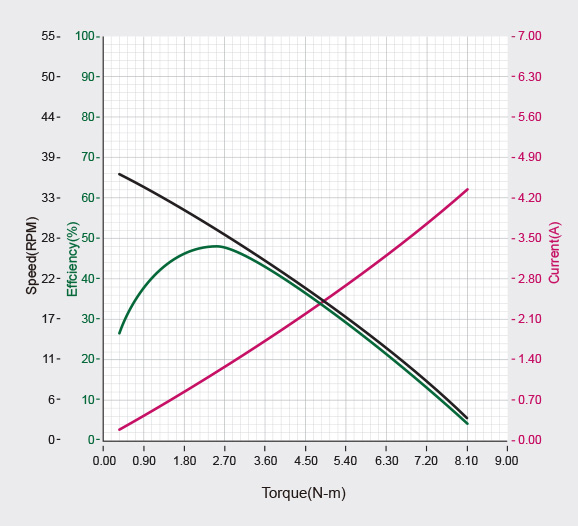
Performance Graph
 Looking for the same form factors?
XW Series
| Model | Stall Torque | No Load Speed |
|---|---|---|
| XW540-T260-R | 8.8 [N.m] (at 11.1 [V], 4.5 [A]) 9.5 [N.m] (at 12.0 [V], 4.9 [A]) 11.2 [N.m] (at 14.8 [V], 5.9 [A]) |
37 [rev/min] (at 11.1 [V]) 40 [rev/min] (at 12.0 [V]) 48 [rev/min] (at 14.8 [V]) |
| XW540-T140-R | 6.4 [N.m] (at 11.1 [V], 4.5 [A]) 6.9 [N.m] (at 12.0 [V], 4.9 [A]) 8.3 [N.m] (at 14.8 [V], 5.9 [A]) |
67 [rev/min] (at 11.1 [V] 72 [rev/min] (at 12.0 [V] 88 [rev/min] (at 14.8 [V]) |
XD Series
| Model | Stall Torque | No Load Speed |
|---|---|---|
| XD540-T270-R | 9.2 [N.m] (at 11.1 [V], 4.5 [A]) 9.9 [N.m] (at 12.0 [V], 4.9 [A]) 11.7 [N.m] (at 14.8 [V], 5.9 [A]) |
36 [rev/min] (at 11.1 [V]) 39 [rev/min] (at 12.0 [V]) 46 [rev/min] (at 14.8 [V]) |
| XD540-T150-R | 6.6 [N.m] (at 11.1 [V], 4.5 [A]) 7.1 [N.m] (at 12.0 [V], 4.9 [A]) 8.5 [N.m] (at 14.8 [V], 5.9 [A]) |
66 [rev/min] (at 11.1 [V]) 70 [rev/min] (at 12.0 [V]) 86 [rev/min] (at 14.8 [V]) |
XH Series
| Model | Stall Torque | No Load Speed |
|---|---|---|
| XH540-V270-R | 9.2 [N.m] (at 24 [V], 2.4 [A]) | 34 [rev/min] (at 24 [V]) |
| XH540-W270-T/R | 9.2 [N.m] (at 11.1 [V], 4.5 [A]) 9.9 [N.m] (at 12.0 [V], 4.9 [A]) 11.7 [N.m] (at 14.8 [V], 5.9 [A]) |
36 [rev/min] (at 11.1 [V]) 39 [rev/min] (at 12.0 [V]) 46 [rev/min] (at 14.8 [V]) |
| XH540-V150-R | 6.4 [N.m] (at 24 [V], 2.4 [A]) | 60 [rev/min] (at 24 [V]) |
| XH540-W150-T/R | 6.6 [N.m] (at 11.1 [V], 4.5 [A]) 7.1 [N.m] (at 12.0 [V], 4.9 [A]) 8.5 [N.m] (at 14.8 [V], 5.9 [A]) |
66 [rev/min] (at 11.1 [V]) 70 [rev/min] (at 12.0 [V]) 86 [rev/min] (at 14.8 [V]) |
XM Series
| Model | Stall Torque | No Load Speed |
|---|---|---|
| XM540-W270-T/R | 10.0[N.m] (at 11.1 [V], 4.2 [A]) 10.6 [N.m] (at 12.0 [V], 4.4 [A]) 12.9 [N.m] (at 14.8 [V], 5.5 [A]) |
28 [rev/min] (at 11.1 [V]) 30 [rev/min] (at 12.0 [V]) 37 [rev/min] (at 14.8 [V]) |
| XM540-W150-T/R | 6.9 [N.m] (at 11.1 [V], 4.2 [A]) 7.3 [N.m] (at 12.0 [V], 4.4 [A]) 8.9 [N.m] (at 14.8 [V], 5.5 [A]) |
50 [rev/min] (at 11.1 [V]) 53 [rev/min] (at 12.0 [V]) 66 [rev/min] (at 14.8 [V]) |
NOTE : The given Stall torque rating for a servo is different from it’s continuous output rating, and may also differ from it’s expected real world performance.
Stall torque is the maximum momentary torque output the servo is capable of, an is generally how RC servos are measured. The Performance graph, or N-T curve, from the above graph is measured under conditions simulating a gradually increasing load.
Generally, the Maximum Torque shown through Performance Graph testing is less than the maximum Stall Torque.
The actual real world performance of the servo will generally be closer to the performance graph measurements, not the rated stall torque.
CAUTION - When supplying power:
-
It is recommended to use a ROBOTIS controller or SMPS2DYNAMIXEL power adapter.
-
Do not connect or disconnect DYNAMIXEL actuator cables while power is being supplied.
Control Table
The Control Table is a data structure used by DYNAMIXEL actuators to manage the state of the device. Users can read data registers to get information about the status of the device with Read Instruction Packets, and modify data registers to control the device with Write Instruction Packets.
Control Table, Data, Address
The Control Table is a structure that consists of multiple Data fields to store status or to control the device. Users can check current status of the device by reading a specific Data from the Control Table with Read Instruction Packets. WRITE Instruction Packets enable users to control the device by changing specific Data in the Control Table. The Address is a unique value when accessing a specific Data in the Control Table with Instruction Packets. In order to read or write data, users must designate a specific Address in the Instruction Packet. Please refer to DYNAMIXEL Protocol 2.0 for more details about Instruction Packets.
NOTE : Two’s complement is applied for the negative value. For more information, please refer to Two’s complement from Wikipedia.
Area (EEPROM, RAM)
The Control Table is divided into 2 Areas. Data in the RAM Area is reset to initial values when the power is reset(Volatile). On the other hand, data in the EEPROM Area is maintained even when the device is powered off(Non-Volatile).
Data in the EEPROM Area can only be written to if Torque Enable(64) is cleared to ‘0’(Torque OFF).
Size
The Size of data varies from 1 ~ 4 bytes depend on their usage. Please check the size of data when updating the data with an Instruction Packet. For data larger than 2 bytes will be saved according to Little Endian.
Access
The Control Table has two different access properties. ‘RW’ property stands for read and write access permission while ‘R’ stands for read only access permission. Data with the read only property cannot be changed by the WRITE Instruction. Read only property(‘R’) is generally used for measuring and monitoring purpose, and read write property(‘RW’) is used for controlling device.
Initial Value
Each data in the Control Table is restored to initial values when the device is turned on. Default values in the EEPROM area are initial values of the device (factory default settings). If any values in the EEPROM area are modified by a user, modified values will be restored as initial values when the device is turned on. Initial Values in the RAM area are restored when the device is turned on.
Control Table of EEPROM Area
| Address | Size(Byte) | Data Name | Access | Initial Value |
Range | Unit |
|---|---|---|---|---|---|---|
| 0 | 2 | Model Number | R | 1,100 | - | - |
| 2 | 4 | Model Information | R | - | - | - |
| 6 | 1 | Firmware Version | R | - | - | - |
| 7 | 1 | ID | RW | 1 | 0 ~ 252 | - |
| 8 | 1 | Baud Rate | RW | 1 | 0 ~ 7 | - |
| 9 | 1 | Return Delay Time | RW | 250 | 0 ~ 254 | 2 [μsec] |
| 10 | 1 | Drive Mode | RW | 0 | 0 ~ 15 | - |
| 11 | 1 | Operating Mode | RW | 3 | 0 ~ 16 | - |
| 12 | 1 | Secondary(Shadow) ID | RW | 255 | 0 ~ 252 | - |
| 13 | 1 | Protocol Type | RW | 2 | 1 ~ 2 | - |
| 20 | 4 | Homing Offset | RW | 0 | -1,044,479 ~ 1,044,479 |
1 [pulse] |
| 24 | 4 | Moving Threshold | RW | 10 | 0 ~ 1,023 | 0.229 [rev/min] |
| 31 | 1 | Temperature Limit | RW | 80 | 0 ~ 100 | 1 [°C] |
| 32 | 2 | Max Voltage Limit | RW | 160 | 95 ~ 160 | 0.1 [V] |
| 34 | 2 | Min Voltage Limit | RW | 95 | 95 ~ 160 | 0.1 [V] |
| 36 | 2 | PWM Limit | RW | 885 | 0 ~ 885 | 0.113 [%] |
| 38 | 2 | Current Limit | RW | 2,047 | 0 ~ 2,047 | 2.69 [mA] |
| 44 | 4 | Velocity Limit | RW | 167 | 0 ~ 1023 | 0.229 [rev/min] |
| 48 | 4 | Max Position Limit | RW | 4,095 | 0 ~ 4,095 | 1 [pulse] |
| 52 | 4 | Min Position Limit | RW | 0 | 0 ~ 4,095 | 1 [pulse] |
| 56 | 1 | External Port Mode 1 | RW | 3 | 0 ~ 3 | - |
| 57 | 1 | External Port Mode 2 | RW | 3 | 0 ~ 3 | - |
| 58 | 1 | External Port Mode 3 | RW | 3 | 0 ~ 3 | - |
| 60 | 1 | Startup Configuration | RW | 0 | 3 | - |
| 63 | 1 | Shutdown | RW | 52 | - | - |
Control Table of RAM Area
| Address | Size(Byte) | Data Name | Access | Initial Value |
Range | Unit |
|---|---|---|---|---|---|---|
| 64 | 1 | Torque Enable | RW | 0 | 0 ~ 1 | - |
| 65 | 1 | LED | RW | 0 | 0 ~ 1 | - |
| 68 | 1 | Status Return Level | RW | 2 | 0 ~ 2 | - |
| 69 | 1 | Registered Instruction | R | 0 | 0 ~ 1 | - |
| 70 | 1 | Hardware Error Status | R | 0 | - | - |
| 76 | 2 | Velocity I Gain | RW | 1,920 | 0 ~ 16,383 | - |
| 78 | 2 | Velocity P Gain | RW | 100 | 0 ~ 16,383 | - |
| 80 | 2 | Position D Gain | RW | 0 | 0 ~ 16,383 | - |
| 82 | 2 | Position I Gain | RW | 0 | 0 ~ 16,383 | - |
| 84 | 2 | Position P Gain | RW | 800 | 0 ~ 16,383 | - |
| 88 | 2 | Feedforward 2nd Gain | RW | 0 | 0 ~ 16,383 | - |
| 90 | 2 | Feedforward 1st Gain | RW | 0 | 0 ~ 16,383 | - |
| 98 | 1 | Bus Watchdog | RW | 0 | 1 ~ 127 | 20 [msec] |
| 100 | 2 | Goal PWM | RW | - | -PWM Limit(36) ~ PWM Limit(36) |
0.113 [%] |
| 102 | 2 | Goal Current | RW | - | -Current Limit(38) ~ Current Limit(38) |
2.69 [mA] |
| 104 | 4 | Goal Velocity | RW | - | -Velocity Limit(44) ~ Velocity Limit(44) |
0.229 [rev/min] |
| 108 | 4 | Profile Acceleration | RW | 0 | 0 ~ 32,767 0 ~ 32,737 |
214.577 [rev/min2] 1 [ms] |
| 112 | 4 | Profile Velocity | RW | 0 | 0 ~ 32,767 | 0.229 [rev/min] |
| 116 | 4 | Goal Position | RW | - | Min Position Limit(52) ~ Max Position Limit(48) |
1 [pulse] |
| 120 | 2 | Realtime Tick | R | - | 0 ~ 32,767 | 1 [msec] |
| 122 | 1 | Moving | R | 0 | 0 ~ 1 | - |
| 123 | 1 | Moving Status | R | 0 | - | - |
| 124 | 2 | Present PWM | R | - | - | - |
| 126 | 2 | Present Current | R | - | - | 2.69 [mA] |
| 128 | 4 | Present Velocity | R | - | - | 0.229 [rev/min] |
| 132 | 4 | Present Position | R | - | - | 1 [pulse] |
| 136 | 4 | Velocity Trajectory | R | - | - | 0.229 [rev/min] |
| 140 | 4 | Position Trajectory | R | - | - | 1 [pulse] |
| 144 | 2 | Present Input Voltage | R | - | - | 0.1 [V] |
| 146 | 1 | Present Temperature | R | - | - | 1 [°C] |
| 147 | 1 | Backup Ready | R | - | 0 ~ 1 | - |
| 152 | 2 | External Port Data 1 | RW | - | - | - |
| 154 | 2 | External Port Data 2 | RW | - | - | - |
| 156 | 2 | External Port Data 3 | RW | - | - | - |
| 168 | 2 | Indirect Address 1 | RW | 224 | 64 ~ 661 | - |
| 170 | 2 | Indirect Address 2 | RW | 225 | 64 ~ 661 | - |
| 172 | 2 | Indirect Address 3 | RW | 226 | 64 ~ 661 | - |
| … | … | … | … | … | - | - |
| 218 | 2 | Indirect Address 26 | RW | 249 | 64 ~ 661 | - |
| 220 | 2 | Indirect Address 27 | RW | 250 | 64 ~ 661 | - |
| 222 | 2 | Indirect Address 28 | RW | 251 | 64 ~ 661 | - |
| 224 | 1 | Indirect Data 1 | RW | 0 | 0 ~ 255 | - |
| 225 | 1 | Indirect Data 2 | RW | 0 | 0 ~ 255 | - |
| 226 | 1 | Indirect Data 3 | RW | 0 | 0 ~ 255 | - |
| … | … | … | … | … | - | - |
| 249 | 1 | Indirect Data 26 | RW | 0 | 0 ~ 255 | - |
| 250 | 1 | Indirect Data 27 | RW | 0 | 0 ~ 255 | - |
| 251 | 1 | Indirect Data 28 | RW | 0 | 0 ~ 255 | - |
| 578 | 2 | Indirect Address 29 | RW | 634 | 64 ~ 661 | - |
| 580 | 2 | Indirect Address 30 | RW | 635 | 64 ~ 661 | - |
| 582 | 2 | Indirect Address 31 | RW | 636 | 64 ~ 661 | - |
| … | … | … | … | … | - | - |
| 628 | 2 | Indirect Address 54 | RW | 659 | 64 ~ 661 | - |
| 630 | 2 | Indirect Address 55 | RW | 660 | 64 ~ 661 | - |
| 632 | 2 | Indirect Address 56 | RW | 661 | 64 ~ 661 | - |
| 634 | 1 | Indirect Data 29 | RW | 0 | 0 ~ 255 | - |
| 635 | 1 | Indirect Data 30 | RW | 0 | 0 ~ 255 | - |
| 636 | 1 | Indirect Data 31 | RW | 0 | 0 ~ 255 | - |
| … | … | … | … | … | - | - |
| 659 | 1 | Indirect Data 54 | RW | 0 | 0 ~ 255 | - |
| 660 | 1 | Indirect Data 55 | RW | 0 | 0 ~ 255 | - |
| 661 | 1 | Indirect Data 56 | RW | 0 | 0 ~ 255 | - |
CAUTION : Protocol 1.0 does not support addresses greater than 256. Therefore, Indirect Address 29 ~ 56 and Indirect Data 29 ~ 56 can only be accessed with Protocol 2.0.
Control Table Description
CAUTION : Data in the EEPROM Area can only be written when the value of Torque Enable(64) is cleared to ‘0’.
Model Number(0)
This address stores model number of DYNAMIXEL.
Firmware Version(6)
This address stores firmware version of DYNAMIXEL.
ID(7)
The ID is a unique value in the network to identify each DYNAMIXEL with an Instruction Packet. 0~252 (0xFC) values can be used as an ID, and 254(0xFE) is occupied as a broadcast ID. The Broadcast ID(254, 0xFE) can send an Instruction Packet to all connected DYNAMIXEL simultaneously.
NOTE : Please avoid using an identical ID for multiple DYNAMIXEL. You may face communication failure or may not be able to detect DYNAMIXEL with an identical ID.
NOTE : If the Instruction Packet ID is set to the Broadcast ID(0xFE), Status Packets will not be returned for READ or WRITE Instructions regardless of the set value of Stuatus Return Level (68). For more details, please refer to the Status Packet section for DYNAMIXEL Protocol 2.0
Baud Rate(8)
The Baud Rate(8) determines serial communication speed between a controller and DYNAMIXEL.
| Value | Baud Rate | Margin of Error |
|---|---|---|
| 7 | 4.5M [bps] | 0.000 [%] |
| 6 | 4M [bps] | 0.000 [%] |
| 5 | 3M [bps] | 0.000 [%] |
| 4 | 2M [bps] | 0.000 [%] |
| 3 | 1M [bps] | 0.000 [%] |
| 2 | 115,200 [bps] | 0.000 [%] |
| 1(Default) | 57,600 [bps] | 0.000 [%] |
| 0 | 9,600 [bps] | 0.000 [%] |
NOTE : Less than 3% of the baud rate error margin will not affect to UART communication.
NOTE : For the stable communication with higher Baudrate using U2D2, configure USB Latency value to the lower.
USB Latency Setting
Return Delay Time(9)
If the DYNAMIXEL receives an Instruction Packet, it will return the Status Packet after the time of the set Return Delay Time(9).
Note that the range of values is 0 to 254 (0XFE) and its unit is 2 [μsec]. For instance, if the Return Delay Time(9) is set to ‘10’, the Status Packet will be returned after 20[μsec] when the Instruction Packet is received.
| Unit | Value Range | Description |
|---|---|---|
| 2[μsec] | 0 ~ 254 | Default value ‘250’(500[μsec]) Maximum value: ‘508’[μsec] |
Drive Mode(10)
The Drive Mode(10) configures Drive Mode of DYNAMIXEL.
| Bit | Item | Description | |
|---|---|---|---|
| Bit 7(0x80) | - | Unused, always ‘0’ | |
| Bit 6(0x40) | - | Unused, always ‘0’ | |
| Bit 5(0x20) | - | Unused, always ‘0’ | |
| Bit 4(0x10) | - | Unused, always ‘0’ | |
| Bit 3(0x08) | Torque On by Goal Update | [0] Performing a given command only if the value of Torque Enable(64) is ‘1’ [1] Performing a given command regardless of the set value of Torque Enable(64). If the value of Torque Enable(64) is ‘0’ and the command is given, the Torque Enable(64) switches to ‘1’ and perform the command. |
|
| Bit 2(0x04) | Profile Configuration | [0] Velocity-based Profile: Create a Profile based on Velocity [1] Time-based Profile: Create Profile based on time ※ See What is the Profile |
|
| Bit 1(0x02) | Master/Slave Mode (Dual Joint) |
[0] Master Mode: Operate as a Master DYNAMIXEL. [1] Slave Mode: Operate as Slave DYNAMIXEL |
|
| Bit 0(0x01) | Normal/Reverse Mode | [0] Normal Mode: CCW(Positive), CW(Negative) [1] Reverse Mode: CCW(Negative), CW(Positive) |
NOTE : Time-based Profile is available from firmware V42.
NOTE: Torque On by Goal Update is available from firmware V45.
NOTE : If the value of Bit 0(Normal/Reverse Mode) of the Drive Mode(10) is set to 1, rotational direction is inverted.
Thus, Position, Velocity, Current, PWM will have a inverted direction.
This feature can be very useful when configuring symmetrical joint.
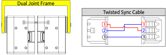
Dual Mode
Dual Mode is intended to combine two DYNAMIXEL into a single joint to enhance the performance.
In order to use Dual Mode, Slave DYNAMIXEL should be connected to Master DYNAMIXEL with the Sync Cable.
Please note that the Slave DYNAMIXEL is directly controlled only by the PWM signal from the Master DYNAMIXEL through the Sync Cable.
Thus, Goal Position, Goal Velocity, Goal Current, Goal PWM of the Slave DYNAMIXEL are unused and ignored.
The rotational direction of Slave DYNAMIXEL is decided by the type of Sync Cable rather than the Normal/Reverse Mode setting of Slave DYNAMIXEL.
The twisted sync cable will actuate the Slave DYNAMIXEL to the opposite direction of the Master DYNAMIXEL while regular sync cable actuate to the same direction.
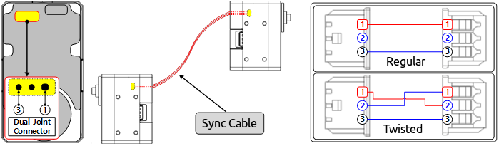
| Sync Cable | Description |
|---|---|
| Regular Sync Cable | Slave DYNAMIXEL is controlled by the PWM Signal from the Master DYNAMIXEL.Master and Slave DYNAMIXEL rotate in the same direction. |
| Twisted Sync Cable | Slave DYNAMIXEL is controlled by the Inverted PWM Signal from the Master DYNAMIXEL.Master and Slave DYNAMIXEL rotate in the opposite direction. |
CAUTION : If Master and Slave are not physically connected by frame, both DYNAMIXEL may not perfectly synchronized due to the load applied on each DYNAMIXEL.
Please use appropriate frame to connect DYNAMIXEL in Dual Mode.
Operating Mode(11)
| Value | Operating Mode | Description |
|---|---|---|
| 0 | Current Control Mode | DYNAMIXEL only controls current(torque) regardless of speed and position. This mode is ideal for a gripper or a system that only uses current(torque) control or a system that has additional velocity/position controllers. |
| 1 | Velocity Control Mode | This mode controls velocity. This mode is identical to the Wheel Mode(endless) from existing DYNAMIXEL. This mode is ideal for wheel-type robots. |
| 3(Default) | Position Control Mode | This mode controls position. This mode is identical to the Joint Mode from existing DYNAMIXEL. Operating position range is limited by the Max Position Limit(48) and the Min Position Limit(52). This mode is ideal for articulated robots that each joint rotates less than 360 degrees. |
| 4 | Extended Position Control Mode(Multi-turn) | This mode controls position. This mode is identical to the Multi-turn Position Control from existing DYNAMIXEL. 512 turns are supported(-256[rev] ~ 256[rev]). This mode is ideal for multi-turn wrists or conveyer systems or a system that requires an additional reduction gear. Note that Max Position Limit(48), Min Position Limit(52) are not used on Extended Position Control Mode. |
| 5 | Current-based Position Control Mode | This mode controls both position and current(torque). Up to 512 turns are supported(-256[rev] ~ 256[rev]). This mode is ideal for a system that requires both position and current control such as articulated robots or grippers. |
| 16 | PWM Control Mode (Voltage Control Mode) | This mode directly controls PWM output. (Voltage Control Mode) |
NOTE : When the Operating Mode(11) switches to another mode, value of Gains, such as Velocity PI(76, 78); Position PID(80, 82, 84); Feedforward(88, 90), will be reset fitting to a selected Operating Mode(11). Beside, the profile generator and the data of determining the limit value will be reset either. See the next description for more details.
- The Profile Velocity(112), Profile Acceleration(108) : Reset to ‘0’
- The Goal PWM(100) and Goal Current(102) are reset to the value of PWM Limit(36) and Current Limit(38) respectively
- When the Operating Mode(11) is Current-based Position Control Mode, Position PID(80, 82, 84) and PWM Limit(36) values will be reset.
Note that the changed value of Position PID(80, 82, 84) and PWM Limit(36) can be read via the Control Table.
NOTE : PWM stands for Pulse Width Modulation that modulates PWM Duty to control motors. It changes pulse width to control average supply voltage to the motor, and this technique is widely used in the motor control field.
- PWM Control Mode is similar to the Wheel Mode of AX and RX series.
- Input Goal PWM(100) value to control supply voltage for DYNAMIXEL in PWM Control Mode.
NOTE : Present Position(132) represents a 4 byte continuous range from -2,147,483,648 to 2,147,483,647 when Torque is turned off regardless of Operating Mode(11).
However, Present Position(132) will be reset to an absolute position value within one full rotation in the following cases:
- When the Operating Mode(11) is changed to Position Control Mode.
- When torque is turned on in Position Control Mode.
- When the actuator is turned on or when rebooted using a Reboot Instruction.
Note that a Present Position(132) value that has been reset to the absolute value within a single rotation will still be affected by the configured Homing Offset(20) value.
Secondary(Shadow) ID(12)
The Secondary(Shadow) ID(12) assigns a secondary ID to the DYNAMIXEL.
The Secondary ID(12) can be shared to group between DYNAMIXELs and to synchronize their movement, unlike ID(7) which must be unique and not be overlapped to use.
Be aware of differences between the Secondary ID(12) and ID(7) by reading the following.
- Under the same Secondary ID(12), multiple DYNAMIXELs can be grouped.
- The ID(7) has a greater priority than the Secondary ID(12). If the data of Secondary ID(12) and ID(7) are set as same, the ID(7) will be applied at the top priority.
- The EEPROM area of the Control Table cannot be modified using Secondary ID(12).
- The RAM area can be modified using the Secondary ID(12).
- If Instruction Packet ID is the same as the Secondary ID(12), the Status Packet will not be returned.
- If the value of the Secondary ID(12) is 253 or higher, the Secondary ID function will be deactivated.
| Values | Description |
|---|---|
| 0 ~ 252 | Activate Secondary ID function |
| 253 ~ 255 | Deactivate Secondary ID function, Default value ‘255’ |
Secondary ID(12) Example
As mentioned, the Secondary ID(12) can be assigned with the same values unlike the ID(7). See the following Secondary ID(12) example to understand the address properly. Note that The assigned ID(7) on each DYNAMIXELs is ‘1’, ‘2’, ‘3’, ‘4’ or ‘5’ and they are not overlapped to be assigned.
- Set Secondary ID of five DYNAMIXELs (Assigned ID(7) of each is ‘1’,’2’,’3’,’4’ or ‘5’, not overlapped) to ‘5’.
- Send Write Instruction Packet(ID(7) = 1, LED(65) = 1).
- The DYNAMIXEL with ID ‘1’ turns on its LED by the Instruction Packet, and Status Packet will be returned.
- Send Write Instruction Packet(ID(7) = 5, LED(65) = 1).
- All DYNAMIXELs turns on their LED, but Status Packet of ID ‘5’ will be returned only.
- Set the Secondary ID of all DYNAMIXELs to ‘100’.
- Send Write Instruction Packet(ID(7) = 100, LED(65) = 0).
- All DYNAMIXELs turns off their LED. As no DYNAMIXEL uses ID 100, but uses the same Secondary ID, the Status Packet will not be returned.
Protocol Type(13)
DYNAMIXEL protocol type (either DYNAMIXEL Protocol 1.0 or 2.0) can be selected using Protocol Type(13).
It is recommended to use an identical protocol type for multiple DYNAMIXEL.
| Value | Description | Compatible DYNAMIXEL |
|---|---|---|
| 1 | DYNAMIXEL Protocol 1.0 | AX Series, DX Series, RX Series, EX Series, MX Series with Firmware below v39 |
| 2(default) | DYNAMIXEL Protocol 2.0 | MX-28/64/106 with Firmware v39 or above, X Series, PRO Series |
WARNING : To modify the data of Protocol Type(13), use the DYNAMIXEL Wizard 2.0 as R+ Manager 2.0 is not compatible with the Protocol 1.0 products.
NOTE : The protocol 2.0 is more stable and safety for use than Protocol 1.0. Accessing some of the Control Table area might be denied if protocol 1.0 is selected. This manual complies with protocol 2.0. Please refer to the Protocol 1.0 and Protocol 2.0 of e-Manual for more details about the protocol.
NOTE : Please refer to the Protocol Compatibility table for product.
Homing Offset(20)
The Home Offset(20) adjusts the home position. The offest value is added to the Present Position(132).
Present Position(132) = Actual Position + Homing Offset(20)
| Unit | Value Range |
|---|---|
| about 0.088 [°] | -1,044,479 ~ 1,044,479 (-255 ~ 255[rev]) |
NOTE : In case of the Position Control Mode(Joint Mode) that rotates less than 360 degrees, any invalid Homing Offset(20) values will be ignored(valid range : -1,024 ~ 1,024).
WARNING : Even if Drive Mode(10) is set to the Reverse Mode, the sign of Homing Offset(20) value is not reversed.
Moving Threshold(24)
The Moving Threshold(24) determines whether the DYNAMIXEL is in motion or not.
When the absolute value of Present Velocity(128) is greater than the Moving Threshold(24), Moving(122) is set to ‘1’. Otherwise it is cleared to ‘0’.
| Unit | Range | Description |
|---|---|---|
| about 0.229 rpm | 0 ~ 1,023 | All velocity related Data uses the same unit |
Temperature Limit(31)
The Temperature Limit(31) limits operating temperature of the DYNAMIXEL.
When the Present Temperature(146) is greater than the Temperature Limit(31), the Overheating Error Bit(0x04) and Alert Bit(0x80) in the Hardware Error Status(70) will be set. If Overheating Error Bit(0x04) is configured in the Shutdown(63), Torque Enable(64) will be set to ‘0’ (Torque OFF).
See the Shutdown(63) for more detailed information.
| Unit | Value Range | Description |
|---|---|---|
| About 1° | 0 ~ 100 | 0 ~ 100° |
CAUTION : Do not set this value higher than its default. In case that DYNAMIXEL encounters temperature warning alarm (Overheating Error Bit(0x04)), let it cool for 20 minutes or more. Otherwise, it may cause severe damage in operating.
Min/Max Voltage Limit(34, 32)
The Min Voltage Limit(32) and Max Voltage Limit(34) determine the maximum and minimum operating voltages.
When the Present Input Voltage(144) indicating the present input voltage to the device exceeds the range of Max Voltage Limit(32) and Min Voltage Limit(34), the Input Voltage error Bit(0x10) in the Hardware Error Status(70) will be set, and the Status Packet will send Alert Bit(0x80) via the Error field.
If Input Voltage Error Bit(0x10) in the Shutdown(63) is set, Torque Enable(64) will be set to ‘0’(Torque OFF).
For more details, please refer to the Shutdown(63) section.
| Unit | Value Range | Description |
|---|---|---|
| About 0.1 [V] | 95 ~ 160 | 9.5 ~ 16.0 [V] |
PWM Limit(36)
The PWM Limit(36) indicates maximum PWM output. Goal PWM(100) can’t be configured with any values exceeding PWM Limit(36). PWM Limit(36) is commonly used in all operating mode as an output limit, therefore decreasing PWM output will result in decreasing torque and velocity. For more details, please refer to the Gain section of each operating modes.
| Unit | Range |
|---|---|
| about 0.113 [%] | 0(0 [%]) ~ 885(100 [%] ) |
Current Limit(38)
The Current Limit(38) indicates maximum current(torque) output limit. The Goal Current(102) can’t be configured with any values exceeding the Current Limit(38). The Current Limit(38) is used in Torque Control Mode and Current-based Position Control Mode, therefore decreasing the Current Limit(38) will result in decreasing torque of DYNAMIXEL. For more details, please refer to the Position PID Gain(80 ~ 84).
| Unit | Value Range |
|---|---|
| about 2.69[mA] | 0 ~ 2,047 |
NOTE : Current Limit(38) could be differ by each DYNAMIXEL so please check the Control Table.
Velocity Limit(44)
Velocity Limit(44) indicates the maximum value of Goal Velocity(104). For more details, see Goal Velocity(104).
| Unit | Value Range |
|---|---|
| 0.229rpm | 0 ~ 1,023 |
NOTE: The default value of Velocity Limit(44) has been decreased since Firmware V42.
Min/Max Position Limit(52, 48)
The Min and Max Position Limit(52, 48) limit the maximum and minimum positions for Position Control Mode(Joint Mode) within the range of 1 rotation(0 ~ 4,095).
Goal Position(116) will also be limited by be the position limit range.
These values are not used in Extended Position Control Mode and Current-based Position Control Mode.
| Unit | Value Range |
|---|---|
| 0.088 [°] | 0 ~ 4,095(1 rotation) |
NOTE : Max Position Limit(48) and Min Position Limit(52) are only used in Position Control Mode with a single turn.
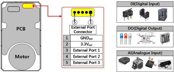
External Port Mode 1,2,3(56,57,58)
External ports that can be used for various purposes are provided.
The property of each port is configured by the External Port Mode and data of external port is controlled by the External Port Data(152~157).
For more details, please refer to External Port Data(152~157).
| External Port Mode | Mode | Description |
|---|---|---|
| 0 | AI(Analogue Input) | Converts External Port signal to 12[bit] digital value |
| 1 | DO_PP(Digital Output Push-Pull) | Use External Port as a digital output port(3.3V level) |
| 2 | DI_PU(Digital Input Pull-Up) | Use External Port as a digital input port Floating connection will be considered as ‘1’ |
| 3(default) | DI_PD(Digital Input Pull-Down) | Use External Port as a digital input port Floating connection will be considered as ‘0’ |
Startup Configuration(60)
The Startup Configuration(60) allows to set up the DYNAMIXEL with specific settings on startup.
| Bit | Item | Description |
|---|---|---|
| Bit 7(0x80) | - | Unused, always ‘0’ |
| Bit 6(0x40) | - | Unused, always ‘0’ |
| Bit 5(0x20) | - | Unused, always ‘0’ |
| Bit 4(0x10) | - | Unused, always ‘0’ |
| Bit 3(0x08) | - | Unused, always ‘0’ |
| Bit 2(0x04) | - | Unused, always ‘0’ |
| Bit 1(0x02) | RAM Restore | [0] Deactivate the RAM area restoration on startup. [1] On startup, use the backup data to restore the RAM area. |
| Bit 0(0x01) | Startup Torque On | [0] Torque Off on startup (Torque Enable(64) is set to 0)[1] Torque On on startup ( Torque Enable(64) is set to 1). |
NOTE: Startup Configuration is available from firmware V45.
NOTE: For more details about restoring the RAM area, see Restoring RAM Area.
Shutdown(63)
The DYNAMIXEL can protect itself by detecting dangerous situations that could occur during the operation. Each Bit is inclusively processed with the ‘OR’ logic, therefore, multiple options can be generated. For instance, when ‘0x05’ (binary : 00000101) is defined in Shutdown(63), DYNAMIXEL can detect both Input Voltage Error(binary : 00000001) and Overheating Error(binary : 00000100). If those errors are detected, Torque Enable(64) is cleared to ‘0’ and the motor’s output becomes 0 [%].
REBOOT is the only method to reset Torque Enable(64) to ‘1’(Torque ON) after the shutdown.
Check Alert Bit(0x80) in an error field of Status Packet or a present status via Hardware Error Status(70). The followings are detectable situations.
| Bit | Item | Description | |
|---|---|---|---|
| Bit 7 | - | Unused, Always ‘0’ | |
| Bit 6 | - | Unused, Always ‘0’ | |
| Bit 5 | Overload Error(default) | Detects that persistent load that exceeds maximum output | |
| Bit 4 | Electrical Shock Error(default) | Detects electric shock on the circuit or insufficient power to operate the motor | |
| Bit 3 | Motor Encoder Error | Detects malfunction of the motor encoder | |
| Bit 2 | Overheating Error(default) | Detects that internal temperature exceeds the configured operating temperature | |
| Bit 1 | - | Unused, Always ‘0’ | |
| Bit 0 | Input Voltage Error | Detects that input voltage exceeds the configured operating voltage |
NOTE :
- If Shutdown occurs, LED will flicker every second. (Firmware v41 or above)
- If Shutdown occurs, reboot the device.
- H/W REBOOT : Turn off and turn on the power again
- S/W REBOOT : Transmit REBOOT Instruction (For more details, refer to the Reboot section of e-Manual.)
Torque Enable(64)
Torque Enable(64) determines Torque ON/OFF. Writing ‘1’ to Torque Enable’s address will turn on the Torque and all Data in the EEPROM area will be locked.
| Value | Description |
|---|---|
| 0(Default) | Torque Off |
| 1 | Torque On and lock EEPROM area |
NOTE : Present Position(132) can be reset when Operating Mode(11) and Torque Enable(64) are updated. For more details, please refer to the Homing Offset(20) and Present Position(132).
LED(65)
The LED(65) determines LED On or Off.
| Bit | Description |
|---|---|
| 0(Default) | Turn OFF the LED |
| 1 | Turn ON the LED |
NOTE : The LED is also used to indicate various statuses of the DYNAMIXEL actuator, refer to the following chart for more information.
| Status | LED Representation |
|---|---|
| Booting | LED blinks once |
| Factory Reset | LED blinks quickly 4 times |
| Shutdown Error | LED blinks continuously |
| Follower Mode | LED blinks quickly 3 times |
| Bootloader Mode | LED on continuously |
Status Return Level(68)
The Stuatus Return Level (68) decides how to return Status Packet when DYNAMIXEL receives an Instruction Packet.
| Value | Responding Instructions | Description |
|---|---|---|
| 0 | PING Instruction | Returns the Status Packet for PING Instruction only |
| 1 | PING Instruction READ Instruction |
Returns the Status Packet for PING and READ Instruction |
| 2 | All Instructions | Returns the Status Packet for all Instructions |
NOTE : If the Instruction Packet ID is set to the Broadcast ID(0xFE), Status Packet will not be returned for READ or WRITE Instructions regardless of Stuatus Return Level (68). For more details, please refer to the Status Packet section for DYNAMIXEL Protocol 2.0.
Registered Instruction(69)
Indicates whether the Write Instruction is registered by Reg Write Instruction
| Value | Description |
|---|---|
| 0 | No instruction registered by REG_WRITE. |
| 1 | Instruction registered by REG_WRITE exists. |
NOTE : If ACTION instruction is executed, the Registered Instruction (69) will be changed to 0.
Hardware Error Status(70)
The Hardware Error Status(70) indicates hardware error status.
The DYNAMIXEL can protect itself by detecting dangerous situations that could occur during the operation. Each Bit is inclusively processed with the ‘OR’ logic, therefore, multiple options can be generated. For instance, when ‘0x05’ (binary : 00000101) is defined in Shutdown(63), DYNAMIXEL can detect both Input Voltage Error(binary : 00000001) and Overheating Error(binary : 00000100). If those errors are detected, Torque Enable(64) is cleared to ‘0’ and the motor’s output becomes 0 [%].
REBOOT is the only method to reset Torque Enable(64) to ‘1’(Torque ON) after the shutdown.
Check Alert Bit(0x80) in an error field of Status Packet or a present status via Hardware Error Status(70). The followings are detectable situations.
| Bit | Item | Description | |
|---|---|---|---|
| Bit 7 | - | Unused, Always ‘0’ | |
| Bit 6 | - | Unused, Always ‘0’ | |
| Bit 5 | Overload Error(default) | Detects that persistent load that exceeds maximum output | |
| Bit 4 | Electrical Shock Error(default) | Detects electric shock on the circuit or insufficient power to operate the motor | |
| Bit 3 | Motor Encoder Error | Detects malfunction of the motor encoder | |
| Bit 2 | Overheating Error(default) | Detects that internal temperature exceeds the configured operating temperature | |
| Bit 1 | - | Unused, Always ‘0’ | |
| Bit 0 | Input Voltage Error | Detects that input voltage exceeds the configured operating voltage |
NOTE :
- If Shutdown occurs, LED will flicker every second. (Firmware v41 or above)
- If Shutdown occurs, reboot the device.
- H/W REBOOT : Turn off and turn on the power again
- S/W REBOOT : Transmit REBOOT Instruction (For more details, refer to the Reboot section of e-Manual.)
Velocity PI Gain(76, 78)
The Velocity PI Gains(76, 78) indicate gains of Velocity Control Mode.
Velocity P Gain of DYNAMIXEL’s internal controller is abbreviated to KVP and that of the Control Table is abbreviated to KVP(TBL).
| Controller Gain | Conversion Equations | Range | Description | |
|---|---|---|---|---|
| Velocity I Gain(76) | KVI | KVI = KVI(TBL) / 65,536 | 0 ~ 16,383 | I Gain |
| Velocity P Gain(78) | KVP | KVP = KVP(TBL) / 128 | 0 ~ 16,383 | P Gain |
Below figure is a block diagram describing the velocity controller in Velocity Control Mode. When the instruction transmitted from the user is received by DYNAMIXEL, it takes following steps until driving the horn.
- An Instruction from the user is transmitted via DYNAMIXEL bus, then registered to Goal Velocity(104).
- Goal Velocity(104) is converted to desired velocity trajectory by Profile Acceleration(108).
- The desired velocity trajectory is stored at Velocity Trajectory(136).
- PI controller calculates PWM output for the motor based on the desired velocity trajectory.
- Goal PWM(100) sets a limit on the calculated PWM output and decides the final PWM value.
- The final PWM value is applied to the motor through an Inverter, and the horn of DYNAMIXEL is driven.
- Results are stored at Present Position(132), Present Velocity(128), Present PWM(124) and Present Current(126).
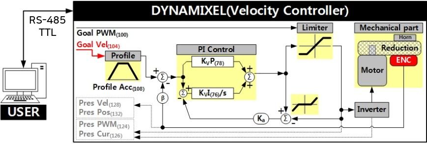
NOTE : Ka stands for Anti-windup Gain and β is a conversion coefficient of position and velocity that cannot be modified by users. For more details about the PID controller, please refer to the PID Controller at wikipedia.
Position PID Gain(80, 82, 84), Feedforward 1st/2nd Gains(88, 90)
These Gains are used in Position Control Mode and Extended Position Control Mode. Position P Gain of DYNAMIXEL’s internal controller is abbreviated to KPP and that of the Control Table is abbreviated to KPP(TBL).
| Controller Gain | Conversion Equations | Range | Description | |
|---|---|---|---|---|
| Position D Gain(80) | KPD | KPD = KPD(TBL) / 16 | 0 ~ 16,383 | D Gain |
| Position I Gain(82) | KPI | KPI = KPI(TBL) / 65,536 | 0 ~ 16,383 | I Gain |
| Position P Gain(84) | KPP | KPP = KPP(TBL) / 128 | 0 ~ 16,383 | P Gain |
| Feedforward 2nd Gain(88) | KFF2nd | KFF2nd(TBL) / 4 | 0 ~ 16,383 | Feedforward Acceleration Gain |
| Feedforward 1st Gain(90) | KFF1st | KFF1st(TBL) / 4 | 0 ~ 16,383 | Feedforward Velocity Gain |
Below figure is a block diagram describing the position controller in Position Control Mode and Extended Position Control Mode. When the instruction from the user is received by DYNAMIXEL, it takes following steps until driving the horn.
- An Instruction from the user is transmitted via DYNAMIXEL bus, then registered to Goal Position(116).
- Goal Position(116) is converted to desired position trajectory and desired velocity trajectory by Profile Velocity(112) and Profile Acceleration(108).
- The desired position trajectory and desired velocity trajectory is stored at Position Trajectory(140) and Velocity Trajectory(136) respectively.
- Feedforward and PID controller calculate PWM output for the motor based on desired trajectories.
- Goal PWM(100) sets a limit on the calculated PWM output and decides the final PWM value.
- The final PWM value is applied to the motor through an Inverter, and the horn of DYNAMIXEL is driven.
- Results are stored at Present Position(132), Present Velocity(128), Present PWM(124) and Present Current(126).
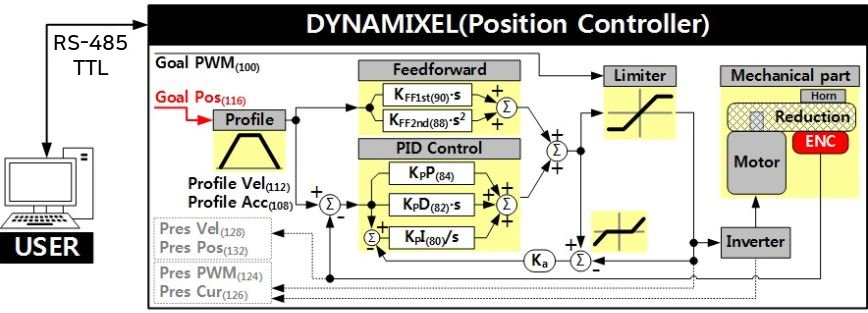
NOTE:
- In case of PWM Control Mode, both PID controller and Feedforward controller are deactivated while Goal PWM(100) value is directly controlling the motor through an inverter. In this manner, users can directly control the supplying voltage to the motor.
- Ka is an Anti-windup Gain that cannot be modified by users.
For more details about the PID controller and Feedforward controller, please refer to the PID Controller and Feed Forward.
Below figure is a block diagram describing the current-based position controller in Current-based Position Control Mode. As Current-based Position Control Mode is quite similar to Position Control Mode, differences will be focused in the following steps. The differences are highlighted with a green marker in the block diagram as well.
- Feedforward and PID controller calculates desired current based on desired trajectory.
- Goal Current(102) decides the final desired current by setting a limit on the calculated desired current.
- Current controller calculates PWM output for the motor based on the final desired current.
- Goal PWM(100) sets a limit on the calculated PWM output and decides the final PWM value.
- The final PWM value is applied to the motor through an Inverter, and the horn of DYNAMIXEL is driven.
- Results are stored at Present Position(132), Present Velocity(128), Present PWM(124) and Present Current(126).
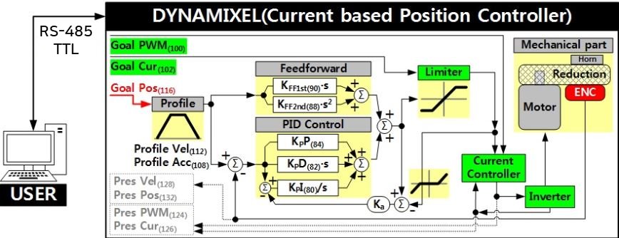
NOTE : Ka is an Anti-windup Gain that cannot be modified by users.
Bus Watchdog(98)
The Bus Watchdog(98) is a safety device (Fail-safe) to stops the DYNAMIXEL if the communication between the controller and DYNAMIXEL communication (RS-485, TTL) is disconnected due to an unspecified error. The communication is defined as all the Instruction Packet in the DYNAMIXEL Protocol.
| Values | Description | |
|---|---|---|
| Range | 0 | Deactivate Bus Watchdog Function, Clear Bus Watchdog Error |
| Range | 1 ~ 127 | Activate Bus Watchdog (Unit: 20 [msec]) |
| Range | -1 | Bus Watchdog Error Status |
The Bus Watchdog function monitors the communication interval (time) between the controller and DYNAMIXEL when Torque Enable(64) is ‘1’(Torque ON).
If the measured communication interval (time) is larger than the set value of Bus Watchdog(98), the DYNAMIXEL will stop. Bus Watchdog(98) will be changed to ‘-1’ (Bus Watchdog Error).
If the Bus Watchdog Error screen appears, the Goal Value (Goal PWM(100), Goal Current(102), Goal Velocity(104), Goal Position(116)) will be changed to read-only-access.
Therefore, if a new value is written to the Goal Value, the Status Packet will send the Data Range Error via its Error field.
If the value of Bus Watchdog(98) is changed to ‘0’, Bus Watchdog Error will be cleared.
NOTE : For details of the Data Range Error, please refer to the Protocol 2.0
NOTE: Bus Watchdog (98) is available from firmware v38.
Bus Watchdog (98) Example
The following is the example of the operation of the Bus Watchdog function.
- After setting the Operating Mode(11) to speed control mode, change the Torque Enable(64) to ‘1’.
- If ‘50’ is written in the Goal Velocity(104), the DYNAMIXEL will rotate in CCW direction.
- Change the value of Bus Watchdog(98) to ‘100’ (2,000 [ms]). (Activate Bus Watchdog Function)
- If no instruction packet is received for 2,000 [ms], the DYNAMIXEL will stop. When it stops, the Profile Acceleration(108) and Profile Velocity(112) are applied as ‘0’.
- The value of Bus Watchdog(98) changes to ‘-1’ (Bus Watchdog Error). At this time, the access to the Goal Value will be changed to read-only.
- If ‘150’ is written to the Goal Velocity(104), the Data Range Error will be returned via Status Packet.
- If the value of Bus Watchdog(98) is changed to ‘0’, Bus Watchdog Error will be cleared.
- If “150” is written in the Goal Velocity(104), the DYNAMIXEL will rotate in CCW direction.
Goal PWM(100)
When the Operating Mode(11) is PWM Control Mode, both the PID and Feedforward controllers will be deactivated as the Goal PWM(100) value directly controls a motor via an inverter. But on the other Operating Mode(11), the Goal PWM(100) limits PWM value only. Read Position PID Gain(80, 82, 84), Feedforward 1st/2nd Gains(88, 90) or Velocity PI Gain(76, 78) for how Goal PWM (100) works with the gains.
| Unit | Range |
|---|---|
| about 0.113 [%] | -PWM Limit(36) ~ PWM Limit(36) |
NOTE: Goal PWM(100) can not exceed PWM Limit(36).
Goal Current(102)
Use Goal Current(102) to set a desired current when the Operating Mode(11) is Torque Control Mode. Also, the Goal Current(102) can be used to set a limit to current in Current-based Position Control Mode. Note that the Goal Current(102) can not be set larger than the Current Limit(38).
| Unit | Value Range |
|---|---|
| about 2.69[mA] | -Current Limit(38) ~ Current Limit(38) |
NOTE: Goal Current(102) can not exceed Current Limit(38).
NOTE : Applying high current to the motor for long period of time might damage the motor.
Goal Velocity(104)
Use the Goal Velocity(104) to set a desired velocity when the Operating Mode(11) is Velocity Control Mode.
Note that the Goal Velocity(104) is not used to limit moving velocity.
| Unit | Value Range |
|---|---|
| 0.229 rpm | -Velocity Limit(44) ~ Velocity Limit(44) |
NOTE: Goal Velocity(104) can not exceed Velocity Limit(44).
NOTE : The maximum velocity and maximum torque of DYNAMIXEL is affected by supplying voltage.
Therefore, if supplying voltage changes, so does the maximum velocity. This manual complies with recommended supply voltage.
NOTE : If Profile Acceleration(108) and Goal Velocity(104) are modified simultaneously, modified Profile Acceleration(108) will be used to process Goal Velocity(104).
Profile Acceleration(108)
When the Drive Mode(10) is Velocity-based Profile, Profile Acceleration(108) sets acceleration of the Profile.
When the Drive Mode(10) is Time-based Profile, Profile Acceleration(108) sets acceleration time of the Profile.
The Profile Acceleration(108) is to be applied in all control mode except Current Control Mode or PWM Control Mode on the Operating Mode(11).
For more detailed information, see What is the Profile
| Velocity-based Profile | Values | Description |
|---|---|---|
| Unit | 214.577 [rev/min2] | Sets acceleration of the Profile |
| Range | 0 ~ 32767 | ‘0’ represents an infinite acceleration |
| Time-based Profile | Values | Description |
|---|---|---|
| Unit | 1 [msec] | Sets accelerating time of the Profile |
| Range | 0 ~ 32737 | ‘0’ represents an infinite acceleration time(‘0 [msec]’). Profile Acceleration(108, Acceleration time) will not exceed 50% of Profile Velocity (112, the time span to reach the velocity of the Profile) value. |
NOTE : Time-based Profile is available from the firmware version 42.
Profile Velocity(112)
When the Drive Mode(10) is Velocity-based Profile, Profile Velocity(112) sets the maximum velocity of the Profile.
When the Drive Mode(10) is Time-based Profile, Profile Velocity(112) sets the time span to reach the velocity (the total time) of the Profile.
Be aware that the Profile Velocity(112) is to be only applied to Position Control Mode, Extended Position Control Mode or Current-based Position Control Mode on the Operating Mode(11).
For more detailed information, see What is the Profile.
NOTE: Velocity Control Mode only uses Profile Acceleration(108) without the Profile Velocity(112).
| Velocity-based Profile | Values | Description |
|---|---|---|
| Unit | 0.229 [rev/min] | Sets velocity of the Profile |
| Range | 0 ~ 32767 | ‘0’ represents an infinite velocity |
| Time-based Profile | Values | Description |
|---|---|---|
| Unit | 1 [msec] | Sets the time span for the Profile |
| Range | 0 ~ 32737 | ‘0’ represents an infinite velocity. Profile Acceleration(108, Acceleration time) will not exceed 50% of Profile Velocity (112, the time span to reach the velocity of the Profile) value. |
NOTE : Time-based Profile is available from the firmware V42.
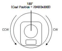
Goal Position(116)
The Goal Position(116) sets desired position. From the front view of DYNAMIXEL, CCW is an increasing direction, whereas CW is a decreasing direction. The way of reaching the Goal Position(116) can differ by the Profile provided by DYNAMIXEL. See the What is the Profile for more details.
| Mode | Values | Description |
|---|---|---|
| Position Control Mode | Min Position Limit(52) ~ Max Position Limit(48) | Initial Value : 0 ~ 4,095 |
| Extended Position Control Mode | -1,048,575 ~ 1,048,575 | -256[rev] ~ 256[rev] |
| Current-based Position Control Mode | -1,048,575 ~ 1,048,575 | -256[rev] ~ 256[rev] |
| Unit | Description |
|---|---|
| 0.088 [deg/pulse] | 1[rev] : 0 ~ 4,095 |
NOTE : The Profile Velocity(112) and the Profile Acceleration(108) are applied in below cases.
- When the Operating Mode(11) is Position Control Mode, the Profile Velocity(112) and the Profile Acceleration(108) are used to create a new profile if the Goal Position(116) is updated.
- When the Operating Mode(11) is Velocity Control Mode, the Profile Acceleration(108) is used to create a new profile if Goal Velocity(104) is updated.
NOTE : When turning off the power supply or changing Operation Mode on Extended Position Control Mode, the value of Present Position is reset to the absolute position value of single turn .
NOTE : Present Position(132) represents a 4 byte continuous range from -2,147,483,648 to 2,147,483,647 when Torque is turned off regardless of Operating Mode(11).
However, Present Position(132) will be reset to an absolute position value within one full rotation in the following cases:
- When the Operating Mode(11) is changed to Position Control Mode.
- When torque is turned on in Position Control Mode.
- When the actuator is turned on or when rebooted using a Reboot Instruction.
Note that a Present Position(132) value that has been reset to the absolute value within a single rotation will still be affected by the configured Homing Offset(20) value.
Realtime Tick(120)
The Realtime Tick(120) indicates DYNAMIXEL’s time.
| Unit | Value Range | Description |
|---|---|---|
| 1 ms | 0 ~ 32,767 | The value resets to ‘0’ when it exceeds 32,767 |
Moving(122)
The Moving(122) indicates whether DYNAMIXEL is in motion or not.
If absolute value of Present Velocity(128) is greater than Moving Threshold(24), Moving(122) is set to ‘1’.
Otherwise, it will be cleared to ‘0’.
However,the Moving(122) will always be set to ‘1’ regardless of Present Velocity(128) while Profile is in progress with Goal Position(116) instruction.
| Value | Description |
|---|---|
| 0 | Movement is not detected |
| 1 | Movement is detected, or Profile is in progress(Goal Position(116) instruction is being processed) |
Moving Status(123)
The Moving Status(123), one byte data, provides additional information about the movement.
Following Error(0x08) and In-Position(0x01) are available under Position Control Mode, Extended Position Control Mode, Current-based Position Control Mode.
For more details about the mode, see the Operating Mode(11).
| Bit | Value | Information | Description |
|---|---|---|---|
| Bit 7 | X | - | Reserved |
| Bit 6 | X | - | Reserved |
| Bit 4 Bit 5 |
11 10 01 00 |
Velocity Profile | 11 : Trapezoidal Profile 10 : Triangular Profile 01 : Rectangular Profile 00 : Profile not used(Step) |
| Bit 3 | 0 or 1 | Following Error | DYNAMIXEL is following the desired position trajectory 0 : Following 1 : Not following |
| Bit 2 | X | - | Reserved |
| Bit 1 | 0 or 1 | Profile Ongoing | Profile is in progress with Goal Position(116) instruction 0 : Profile completed 1 : Profile in progress |
| Bit 0 | 0 or 1 | In-Position | DYNAMIXEL has arrived to the desired position 0 : Not arrived 1 : Arrived |
NOTE : The Triangular velocity profile is configured when Rectangular velocity profile cannot reach to the Profile Velocity(112).
NOTE : In-Position bit will be set when the positional deviation is smaller than a predefined value under Position related control modes.
Present PWM(124)
The Present PWM(124) indicates current PWM. For more details, please refer to the Goal PWM(100).
Present Current(126)
This value indicates current Current. For more details, please refer to the Goal Current(102).
Present Velocity(128)
This value indicates current Velocity. For more details, please refer to the Goal Velocity(104).
Present Position(132)
The Present Position(132) indicates present Position. For more details, see the Goal Position(116).
NOTE : Present Position(132) represents a 4 byte continuous range from -2,147,483,648 to 2,147,483,647 when Torque is turned off regardless of Operating Mode(11).
However, Present Position(132) will be reset to an absolute position value within one full rotation in the following cases:
- When the Operating Mode(11) is changed to Position Control Mode.
- When torque is turned on in Position Control Mode.
- When the actuator is turned on or when rebooted using a Reboot Instruction.
Note that a Present Position(132) value that has been reset to the absolute value within a single rotation will still be affected by the configured Homing Offset(20) value.
Velocity Trajectory(136)
The Velocity Trajectory(136) is a desired velocity trajectory created by Profile. Operating method can be changed based on its Operating Mode(11). For more details, see the What is the Profile.
- Velocity Control Mode : When Profile reaches to the endpoint, The Velocity Trajectory(136) becomes equal to the Goal Velocity(104).
- Position Control Mode, Extended Position Control Mode, Current-based Position Control Mode : Velocity Trajectory is used to create Position Trajectory(140). When Profile reaches to an endpoint, Velocity Trajectory(136) is cleared to ‘0’.
Position Trajectory(140)
The Position Trajectory(140) is a desired position trajectory created by the Profile.
The Position Trajectory(140) is used only when the Operating Mode(11) is the Position Control Mode, Extended Position Control Mode or Current-based Position Control Mode.
For more details, see What is the Profile.
Present Input Voltage(144)
The Present Input Voltage(144) indicates present voltage that is being supplied. For more details, see the Max/Min Voltage Limit(32, 34).
Present Temperature(146)
The Present Temperature(146) indicates internal temperature of DYNAMIXEL. For more details, see the Temperature Limit(31).
Backup Ready(147)
The value in this address indicates whether the backup of the control table exists after sending the Control Table Backup Packet.
| Value | Description |
|---|---|
| 0 | The backup data doesn’t exist. |
| 1 | A saved backup data exists. |
NOTE
Backup Ready is available from firmware V45.
See Backup and Restore for more details.
External Port Data 1,2,3
Through External Port Data, signal on the External Port can be read or data can be written on the External Port.
The External Port is not electrically insulated, therefore abide by the electrical specifications.
For more accurate measurement, use shielded cable or twisted cable.
The shorter the length, the better the result.
| External Port Mode | Access | Details | Electrical Characteristics |
|---|---|---|---|
| Common | - | - | 0 ~ 3.3[V], 0 ~ 5[mA] VESD(HBM) : 2[kV] |
| 0(AI) | Read | Converts External Port signal to digital value External Data = signal x (4,095 / 3.3) |
Resolution : 12[bit] (0 ~ 4,095) |
| 1(DO_PP) | Write | 0 : Set External Port output to 0[V] 1 : Set External Port output to 3.3[V] |
Output High level(VOH) : 2.4 [V] (min) Output Low level(VOL) : 0.5 [V] (max) |
| 2(DI_PU) 3 (DI_PD) |
Read | 0: External Port input is 0[V] 1 : External Port input is 3.3[V] |
Input High level(VIH) : 2.3 [V] (min) Input Low level(VIL) : 1.0 [V] (max) Pull-Up/Down : 40 [kΩ] (typ) |
※ VESD(HBM) : ESD(Electrostatic Discharge) Voltage(human body model)
The External Port is not electrically insulated, therefore, abide by the electrical specifications.
If the electrical specification is exceeded or there is a problem with the signal connection, special caution is required because DYNAMIXEL can be damaged.
- Be careful not to cause electric shock by static electricity (ESD), short circuit, open circuit.
- Be careful not to let water or dust get into the External Port connector.
- If you are not using the External Port, remove the cable.
- To connect or disconnect the External Port, proceed with power off.
- Do not connect the GNDext pin of External Port directly to the GND pin of DYNAMIXEL’s connector. Noise from power may affect on the External Port.
Indirect Address, Indirect Data
Indirect Address and Indirect Data are useful when accessing two remote addresses in the Control Table as sequential addresses. - Sequential addresses increase Instruction Packet efficiency. Addresses that can be defined as Indirect Address is limited to RAM area(Address 64 ~ 661).
- If specific address is allocated to Indirect Address, Indirect Address inherits features and properties of the Data from the specific Address.
- Property includes Size(Byte length), value range, and Access property(Read Only, Read/Write).
- For instance, allocating 65(Address of LED) to Indirect Address 1(168), Indirect Data 1(224) can perform exactly same as LED(65).
| Indirect Address Range | Description |
|---|---|
| 64 ~ 661 | EEPROM address can’t be assigned to Indirect Address |
Indirect Address and Indirect Data Examples
Example 1 Allocating Size 1 byte LED(65) to Indirect Data 1(224).
- Indirect Address 1(168) : change the value to ‘65’ which is the address of LED.
- Set Indirect Data 1(224) to ‘1’ : LED(65) also becomes ‘1’ and LED is turned on.
- Set Indirect Data 1(224) to ‘0’ : LED(65) also becomes ‘0’ and LED is turned off.
Example 2 Allocating Size 4 byte Goal Position(116) to Indirect Data 2(225), 4 sequential bytes have to be allocated.
- Indirect Address 2(170) : change the value to ‘116’ which is the first address of Goal Position.
- Indirect Address 3(172) : change the value to ‘117’ which is the second address of Goal Position.
- Indirect Address 4(174) : change the value to ‘118’ which is the third address of Goal Position.
- Indirect Address 5(176) : change the value to ‘119’ which is the fourth address of Goal Position.
- Set 4 byte value ‘1,024’ to Indirect Data 2 : Goal Position(116) also becomes ‘1024’ and DYNAMIXEL moves.
NOTE : In order to allocate Data in the Control Table longer than 2[byte] to Indirect Address, all address must be allocated to Indirect Address like the above Example 2.
NOTE : Indirect Address 29 ~ 56 and Indirect Data 29 ~ 56 can only be accessed with Protocol 2.0.
How to Assemble
Describes how to assemble the horn (Normal / Idler) and Frame (for Hinge / Side) of DYNAMIXEL, and how to replace the gears in DYNAMIXEL.
Horn Assembly
Normal Horn Assembly
The standard DYNAMIXEL output horn is assembled by attaching it to the output shaft located on the front casing of the DYNAMIXEL servo, and is used to connect the actuator’s output to frames and other accessories.
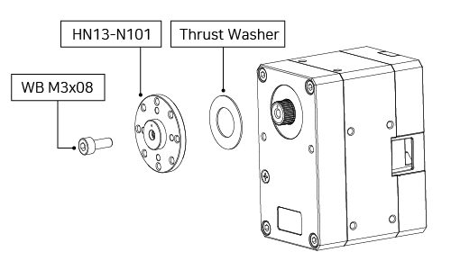
WARNING: Be sure to properly align the thrust washer with the output shaft or the thrust washer may be damaged by the assembled horn.
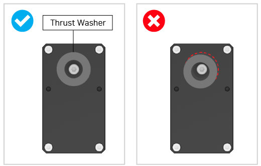
NOTE: Ensure that the indexing mark on the output horn is aligned with the index marking on the output shaft.
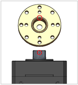
Idler Horn Assembly
An idler horn is required in addition to a DYNAMIXEL’s output horn for installation of hinge frame accessories.
Additionally, the hollow shaft of an installed idler horn provides a neat cable wiring solution.
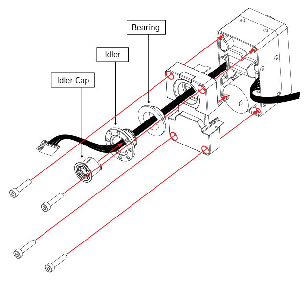
Hollow Shaft cable passthrough information
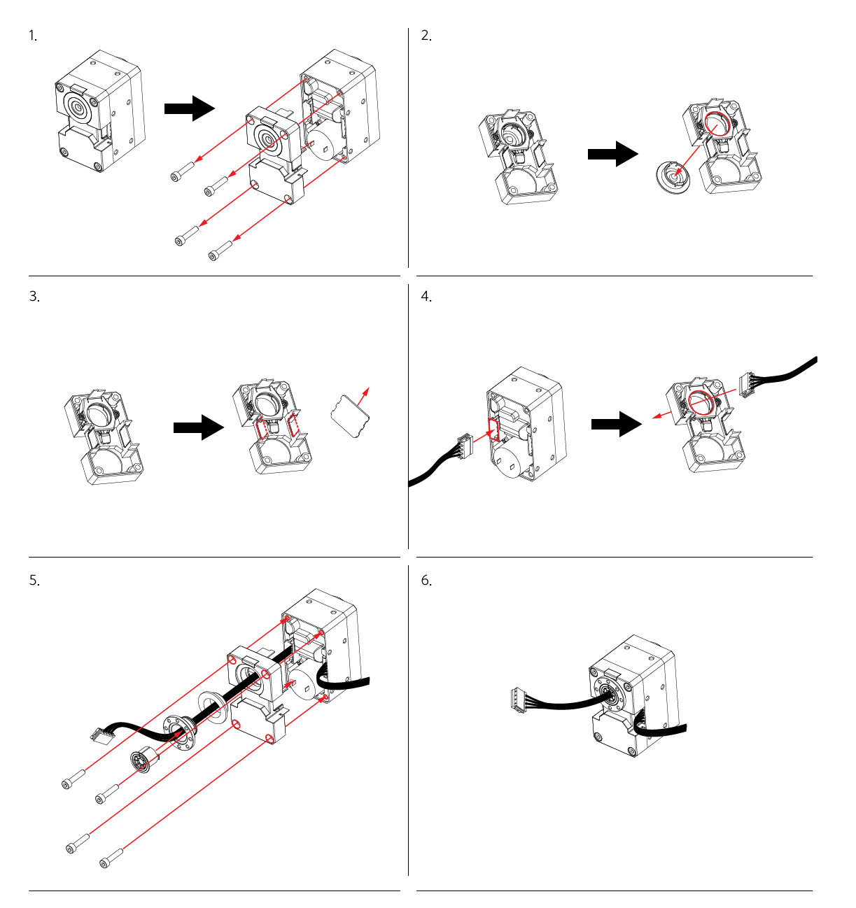
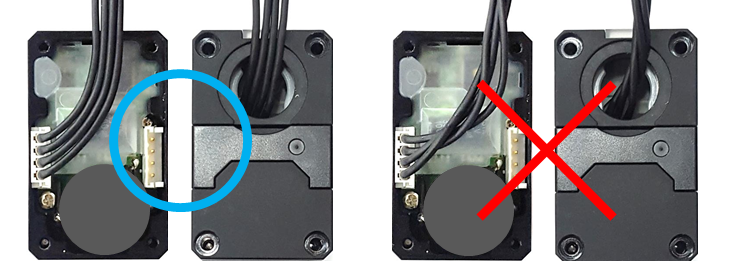
Hollow shaft cable assembly precautions
CAUTION: To ensure correct DYNAMIXEL-X series cable assembly untangle the DYNAMIXEL cable prior to insertion through the hollow shaft. Do not assemble the back case with a tangled cable, tangled cables may be crushed by the case and cause communication errors or damage to your DYNAMIXEL hardware.
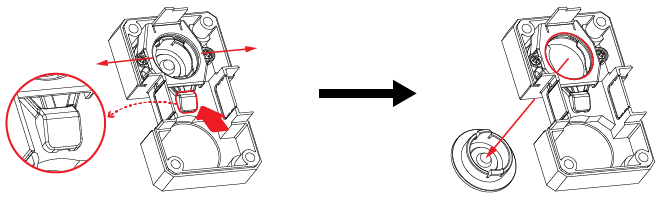
Idler Horn Disassembly
To remove an attached idler horn, push the button located on the reverse side of the back case and gently lift the side hooks to disengage the idler.
Frame Assembly
How To Use Spacer Ring
To prevent damage to your frames during assembly, use the included spacer rings to fill the gaps between assembled frames and your DYNAMIXEL case.
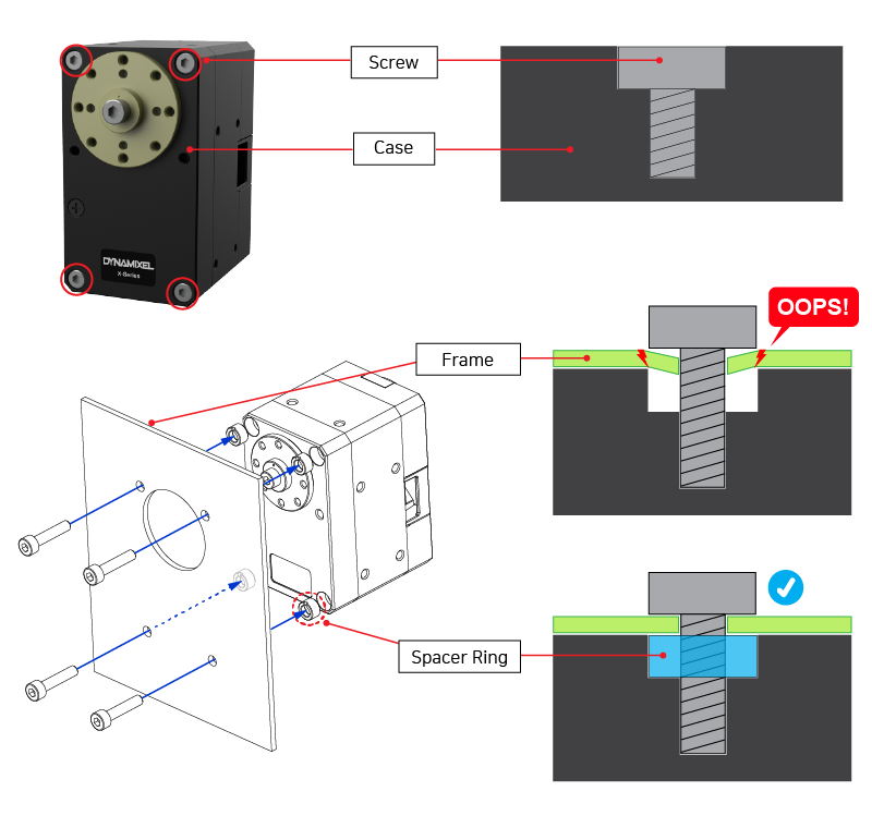
Frame and Horn Assembly Precautions
WARNING: Before assembling your DYNAMIXEL accessories, ensure that all screws and bolts are the correct length by considering the depth of your DYNAMIXEL’s mounting points. If the length of screw is larger than the depth of the mounting point your frame or DYNAMIXEL may be damaged during assembly.
NOTE: Information regarding size and depth of DYNAMIXEL servo mounting points can be found in the Drawings section of the product’s eManual page.
Hinge Frame Assembly
DYNAMIXEL hinge frames are assembled by attaching them to the idler and output horn of your servo.
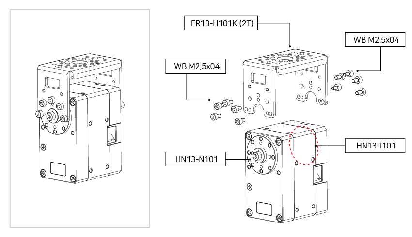
FR13-H101K
NOTE: Information regarding size and depth of DYNAMIXEL servo mounting points can be found in the Drawings section of the product’s eManual page.
NOTE: An idler horn is required for the installation of DYNAMIXEL hinge frames. See the [Idler Horn Assembly] instructions for more information.
WARNING: During hinge assembly, ensure that all screws are the proper length before installation. See [Frame and Horn Assembly Precautions] for more information.
Side Frame Assembly
DYNAMIXEL side frames are assembled by attaching them to the mounting points on the sides of your DYNAMIXEL actuator.
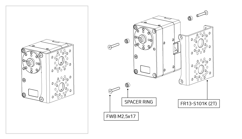
FR13-S101K
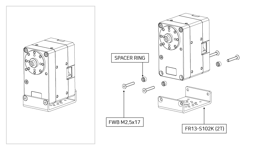
FR13-S102K
NOTE: Information regarding size and depth of DYNAMIXEL servo mounting points can be found in the Drawings section of the product’s eManual page.
NOTE: Use spacer rings to protect assembled DYNAMIXEL frames. See How To Use Spacer Rings for more information.
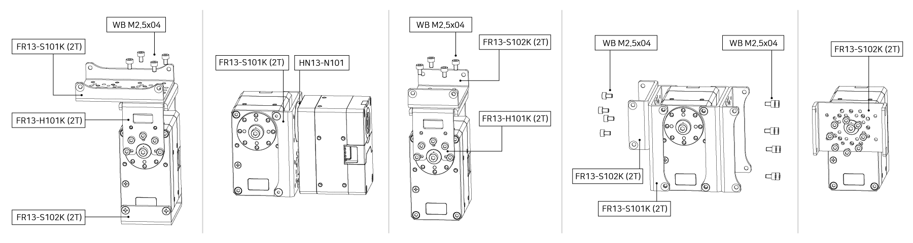
Frame Combination
Hinge and side frames can be combined in a variety of ways to provide complex mounting options.
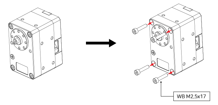
Custom Frame Assembly
Custom made DYNAMIXEL frames can also be installed by following the instructions below.
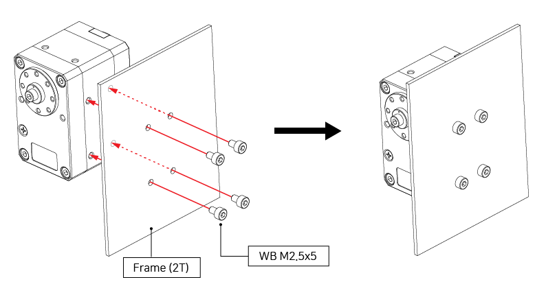
Front (Wrench Bolt)
-
Step 1
-
Step 2
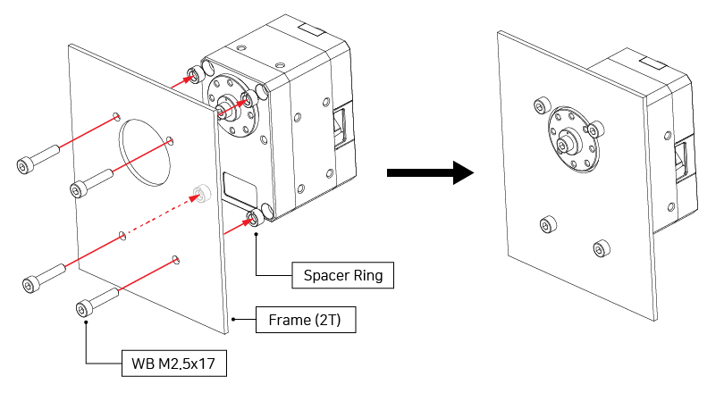
NOTE: The example frame included in the image is not available for sale.
NOTE: Use spacer rings to protect assembled DYNAMIXEL frames see How To Use Spacer Rings for more information.
NOTE: Information regarding size and depth of DYNAMIXEL servo mounting points can be found in the Drawings section of the product’s eManual page.
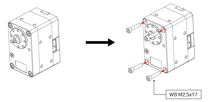
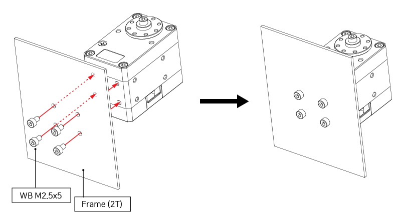
Front (Flat Head Wrench Bolt)
-
Step 1
-
Step 2
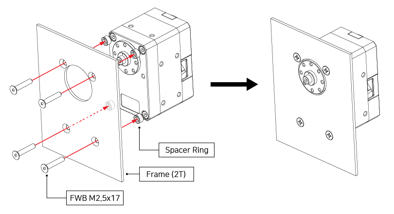
NOTE: The example frame included in the image is not available for sale.
NOTE: Use spacer rings to protect assembled DYNAMIXEL frames see How To Use Spacer Rings for more information.
NOTE: Information regarding size and depth of DYNAMIXEL servo mounting points can be found in the Drawings section of the product’s eManual page.
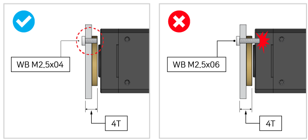
Side
WARNING: Before installing DYNAMIXEL side frames verify that the length of your mounting hardware does not exceed the available depth of the mounting points.
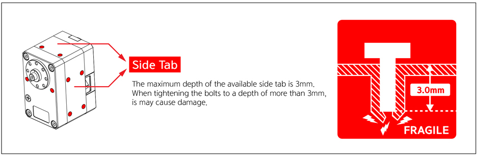
NOTE: The example frame included in the image is not available for sale.
NOTE: Information regarding size and depth of DYNAMIXEL servo mounting points can be found in the Drawings section of the product’s eManual page.
Bottom
WARNING: Before installing DYNAMIXEL side frames verify that the length of your mounting hardware does not exceed the available depth of the mounting points.
NOTE: The example frame included in the image is not available for sale.
NOTE: Information regarding size and depth of DYNAMIXEL servo mounting points can be found in the Drawings section of the product’s eManual page.
Gear Replacement
DYNAMIXEL’s internal gears are subject to wear and tear through regular use. Regular maintenance and replacement of DYNAMIXEL gears is required to ensure maximum performance and precision.
The following video provides instructions on the DYNAMIXEL gear replacement process.
DYNAMIXEL Calibration
After a gear replacement has been completed, your DYNAMIXEL must be recalibrated to ensure positional accuracy.
See the following video on how to calibrate your DYNAMIXEL using R+ Manager 2.0.
NOTE: The USB2Dynamixel serial converter shown in the video above has been discontinued. The U2D2 serial converter is a direct replacement for this component, and should be used instead.
ROBOTIS recommends using the new DYNAMIXEL Wizard 2.0 calibration software rather than our legacy R+ Manager 2.0 software used in the video.
Reference
NOTE:
Compatibility Guide
Harness Compatibility
What is the Profile
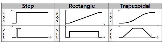
The Profile is a generated movement trajectory intended to reduce vibration, noise and load of the motor by dynamically changing velocity and acceleration during movements.
DYNAMIXEL servos provide 3 different types of Profile:
Profiles are usually selected according to the combination of Profile Velocity(112) and Profile Acceleration(108).
When given a new Goal Position(116), the DYNAMIXEL’s profile settings creates a desired velocity trajectory based on present movement velocity.
When a DYNAMIXEL receives an updated Goal Position(116) while it is moving toward the previous Goal Position(116), velocity is adjusted smoothly to match the new desired velocity trajectory.
The following explains how the Profile processes Goal Position(116) instructions in Current-based Position Control Mode, Position Control mode, and Extended Position Control Mode.
- An Instruction from the user is transmitted via the DYNAMIXEL bus, then registered to Goal Position(116) (If Velocity-based Profile is selected).
- Acceleration time(t1) is calculated based on Profile Velocity(112) and Profile Acceleration(108).
- The type of Profile is decided based on Profile Velocity(112), Profile Acceleration(108) and total travel distance(ΔPos, the distance difference between desired position and present position).
- The selected Profile type is stored at Moving Status(123).
- The DYNAMIXEL is driven by the calculated desired trajectory from the Profile.
- The desired velocity trajectory and desired position trajectory from the Profile are stored at Velocity Trajectory(136) and Position Trajectory(140) respectively.
| Condition | Types of Profile |
|---|---|
| VPRFL(112) = 0 | Profile not used (Step Instruction) |
| (VPRFL(112) ≠ 0) & (APRF(108) = 0) | Rectangular Profile |
| (VPRFL(112) ≠ 0) & (APRF(108) ≠ 0) | Trapezoidal Profile |
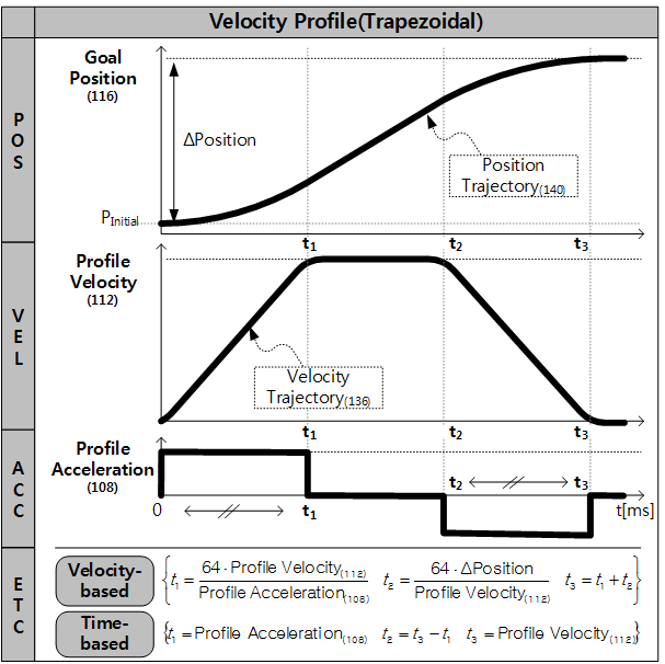
NOTE : Velocity Control Mode only uses Profile Acceleration(108). Step and Trapezoidal Profiles are supported. Acceleration time(t1) can be calculated according to the equation below.
Velocity-based Profile : t1 = 64 * {Profile Velocity(112) / Profile Acceleration(108)}
Time-based Profile : t1 = Profile Acceleration(108)
NOTE : If Time-based Profile is selected, Profile Velocity(112) is used to set the time span of the Profile(t3), while Profile Acceleration(108) sets allowed accelerating time(t1) in millisecond[ms]. Profile Acceleration(108) will not exceed 50% of the configured Profile Velocity(112) value.
Certifications
Please inquire us for information regarding unlisted certifications.
FCC
Note: This equipment has been tested and found to comply with the limits for a Class A digital device, pursuant to part 15 of the FCC Rules. These limits are designed to provide reasonable protection against harmful interference when the equipment is operated in a commercial environment. This equipment generates, uses, and can radiate radio frequency energy and, if not installed and used in accordance with the instruction manual, may cause harmful interference to radio communications. Operation of this equipment in a residential area is likely to cause harmful interference in which case the user will be required to correct the interference at his own expense.
WARNING
Any changes or modifications not expressly approved by the manufacturer could void the user’s authority to operate
the equipment.
Quick Start
Prerequisites
- DYNAMIXEL Power Supply (12V SMPS, or compatible 12v battery.)
- PC with Windows, Linux or MacOS.
- Serial converter to communicate between your PC and DYNAMIXEL (U2D2, OpenRB-150)
- DYNAMIXEL Control Software
WARNING:
- Some software may not support all OS options. Be sure to read the eManual page of any software you wish to use to ensure compatibility.
NOTE:
- The U2D2 is a small size USB to Serial communication converter that enables control and operation of DYNAMIXEL servos directly from a connected PC.
- The U2D2 Power Hub simplifies the process of connecting an external power source to your U2D2 to supply power to your DYNAMIXEL.
Compatible Software with DYNAMIXEL
DYNAMIXEL Wizard 2.0
DYNAMIXEL Wizard 2.0 a configuration tool designed to simplify the setup, configuration and management of DYNAMIXEL servos.
The following features are provided by DYNAMIXEL Wizard 2.0:
- DYNAMIXEL Firmware Update
- DYNAMIXEL Error Diagnosis
- DYNAMIXEL Configuration and Testing
- DYNAMIXEL Real-time Data Plotting
- Generate & Monitor DYNAMIXEL Packets
DYNAMIXEL SDK
DYNAMIXEL SDK is a software development kit that provides DYNAMIXEL control functions for a variety of popular programming languages.
Supported Programming Laguanges and Features:
- C, C++, C#, Python, Java, MATLAB, LabVIEW
- Windows, Mac, Linux.
- ROS
- Arduino
NOTE: You can also use more variety of software. For more information, see the following to check software provided by ROBOTIS.
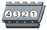
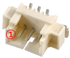
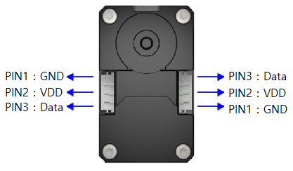
Connector Information
| Item | TTL | RS-485 | External Port | Dual Joint |
|---|---|---|---|---|
| Pinout | 1 GND2 VDD3 DATA |
1 GND2 VDD3 DATA+4 DATA- |
1 GND2 VDD3 PORT 14 PORT 25 PORT 3 |
1 PWM12 PWM23 ENABLE |
| Diagram |  |
 |
 |
 |
| Housing | 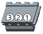 JST EHR-03 |
 JST EHR-04 |
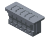 MOLEX 51021-0500 |
 MOLEX 51021-0300 |
| PCB Header | 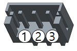 JST B3B-EH-A |
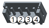 JST B4B-EH-A |
 MOLEX 53047-0510 |
 MOLEX 53398-0371 |
| Crimp Terminal | JST SEH-001T-P0.6 | JST SEH-001T-P0.6 | MOLEX 50079-8100 | MOLEX 50058-8000 |
| Wire Gauge for DYNAMIXEL | 21 AWG | 21 AWG | 26 AWG | 26 AWG |
Communication Circuit
To control the DYNAMIXEL actuators, the main controller needs to convert its UART signals to the half duplex type. The recommended circuit diagram for this is shown below.
TTL Communication
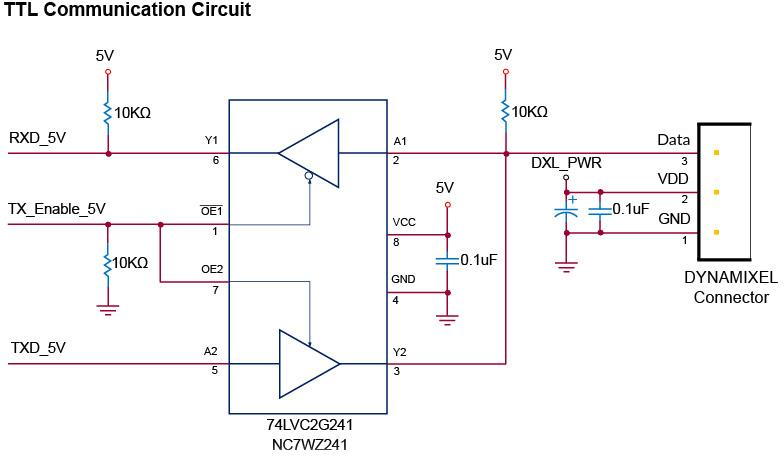
TTL Circuit
NOTE: Above circuit is designed for 5V or 5V tolerant MCU. Otherwise, use a Level Shifter to match the voltage of MCU.
RS-485 Communication
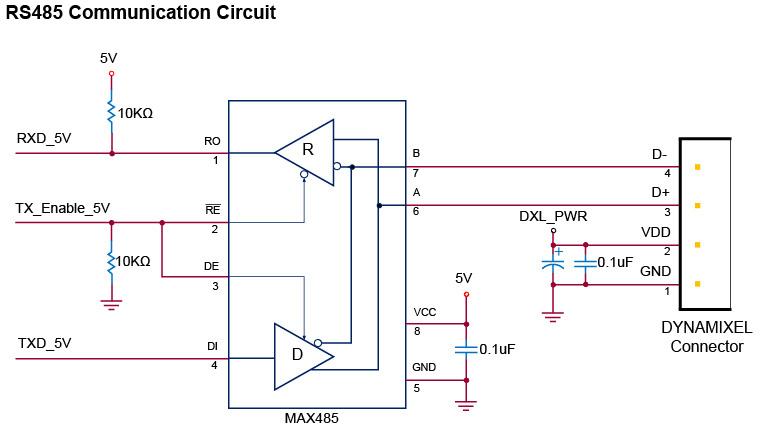
RS-485 Circuit
NOTE: Above circuit is designed for 5V or 5V tolerant MCU. Otherwise, use a Level Shifter to match the voltage of MCU.
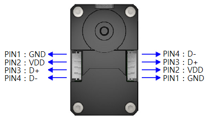
The power of DYNAMIXEL is supplied via Pin1(-), Pin2(+).
(The above circuit is built into DYNAMIXEL’s controller only)
In the above circuit diagram, the direction of data signal of TxD and RxD in the TTL Level is determined according to the level of DIRECTION 485 as follows:
In case of DIRECTION485 Level = High: The signal of TxD is output to D+ and D-
In case of DIRECTION485 Level = Low: The signal of D+ and D- is output to RxD
Drawings
X540
DownloadXM,H,D-540.N101.I101.pdfDownloadXM,H,D-540.N101.I101.dwgDownloadXM,H,D-540.N101.I101.STP
FR13-H101K
Downloadfr13_h101_ref.dwgDownloadfr13_h101_ref.pdfDownloadfr13_h101.stp
FR13-S101K
Downloadfr13_s101_ref.dwgDownloadfr13_s101_ref.pdfDownloadfr13_s101.stp
FR13-S102K
Downloadfr13_s102_ref.dwgDownloadfr13_s102_ref.pdfDownloadfr13_s102.stp
Please also checkout ROBOTIS Download Center for software applications, 3D/2D CAD, and other useful resources!
Moment of Inertia
Downloadxm540,xh540 moment of inertia.pdf