
OpenCR1.0
Overview
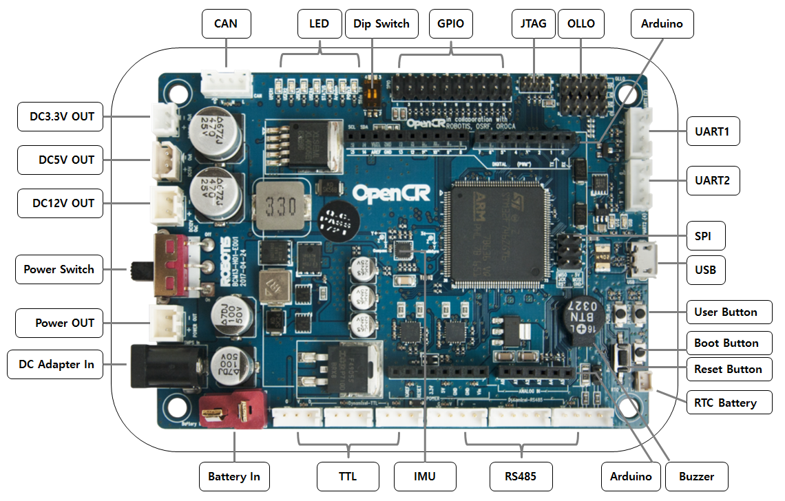
OpenCR is a main controller board of the TurtleBot3. OpenCR; Open-source Control module for ROS, is developed for ROS embedded systems to provide completely open-source hardware and software. Everything about the board; Schematics, PCB Gerber, BOM and the firmware source code for the TurtleBot3 are free to distribute under open-source licenses for users and the ROS community.
The STM32F7 series is a main chip inside the OpenCR board which is based on a very powerful ARM Cortex-M7 with floating point unit. The development environment for OpenCR is wide open from Arduino IDE and Scratch for young students to traditional firmware development for the expert.
OpenCR provides digital and analog input/output pins that can interface with extension board or various sensors. Also, OpenCR features various communication interfaces: USB for connecting to PC, UART, SPI, I2C, CAN for other embedded devices.
OpenCR can provide a best solution when using with a SBC. It supports 12V, 5V, 3.3V power outputs for SBCs and sensors. It also supports hot swap power inputs between battery and SMPS.
OpenCR will be the best solution for implementing your embedded control design.
Specifications
NOTE: Hot swap power switch between shore power(12V, 5A SMPS) and mobile power(battery) from OpenCR board enables UPS(Uninterrupted Power Supply) feature.
| Items | Specifications |
|---|---|
| Microcontroller | STM32F746ZGT6 / 32-bit ARM Cortex®-M7 with FPU (216MHz, 462DMIPS) |
| Sensors | (Discontinued) Gyroscope 3Axis, Accelerometer 3Axis, Magnetometer 3Axis (MPU9250) (New) 3-axis Gyroscope, 3-Axis Accelerometer, A Digital Motion Processor™ (ICM-20648) |
| Programmer | ARM Cortex 10pin JTAG/SWD connector USB Device Firmware Upgrade (DFU) Serial |
| Extension pins | 32 pins (L 14, R 18) *Arduino connectivity Sensor module x 4 pins Extension connector x 18 pins |
| Communication circuits | USB (Micro-B USB connector/USB 2.0/Host/Peripheral/OTG) TTL (B3B-EH-A / DYNAMIXEL) RS485 (B4B-EH-A / DYNAMIXEL) UART x 2 (20010WS-04) CAN (20010WS-04) |
| LEDs and buttons | LD2 (red/green) : USB communication User LED x 4 : LD3 (red), LD4 (green), LD5 (blue) User button x 2 |
| Powers | External input source 5 V (USB VBUS), 7-24 V (Battery or SMPS) Default battery : LI-PO 11.1V 1,800mAh 19.98Wh Default SMPS: 12V 5A External output source 12V@1A(SMW250-02), 5V@4A(5267-02A), 3.3V@800mA(20010WS-02) External battery Port for RTC (Real Time Clock) (Molex 53047-0210) Power LED: LD1 (red, 3.3 V power on) Reset button x 1 (for power reset of board) Power on/off switch x 1 |
| Dimensions | 105(W) X 75(D) mm |
| Mass | 60g |
NOTE: MPU9250 sensor has been replaced with ICM-20648, since 2020, as MPU9250 is discontinued to produce.
User Guide
Run turtlebot3_core node
$ rosrun rosserial_python serial_node.py __name:=turtlebot3_core _port:=/dev/ttyACM0 _baud:=115200
Testing
$ rostopic echo /imu

  seq: 179
  stamp:
    secs: 1486448047
    nsecs: 147523921
  frame_id: imu_link
orientation:
  x: 0.0165222994983
  y: -0.0212152898312
  z: 0.276503056288
  w: 0.960632443428
orientation_covariance: [0.0024999999441206455, 0.0, 0.0, 0.0, 0.0024999999441206455, 0.0, 0.0, 0.0, 0.0024999999441206455]
angular_velocity:
  x: 2.0
  y: 1.0
  z: -1.0
angular_velocity_covariance: [0.019999999552965164, 0.0, 0.0, 0.0, 0.019999999552965164, 0.0, 0.0, 0.0, 0.019999999552965164]
linear_acceleration:
  x: 528.0
  y: 295.0
  z: 16648.0
linear_acceleration_covariance: [0.03999999910593033, 0.0, 0.0, 0.0, 0.03999999910593033, 0.0, 0.0, 0.0, 0.03999999910593033]
---
Debugging
turtlebot3_core.ino includes debugging code to check odometry, connected sensor and state of TurtleBot3 or DYNAMIXEL’s.
This might be help you to implement code and test it without ROS connection.
First, ready to LN-101 or any USB to Serial converter.
Second, open turtlebot3_core_config.h file and activate DEBUG. After that upload it to OpenCR.
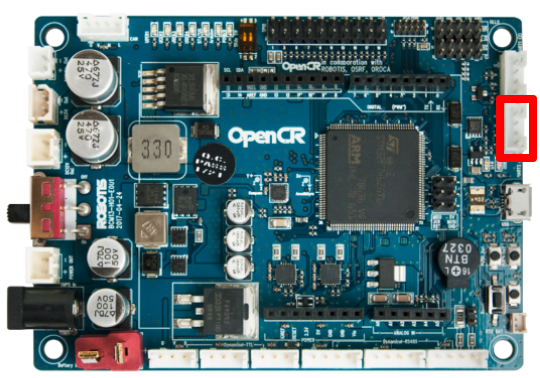
Third, connect converter to UART2 in OpenCR.
Forth, download minicom and configure baudrate 57600 and port name.
$ sudo apt-get install minicom
$ minicom -s
Fifth, press reset button of OpenCR then you can see how turtlebot3_core.ino start and some data.
Success to init Motor Driver
Success to init Sensor
Success to init Diagnosis
Success to init Controller
---------------------------------------
EXTERNAL SENSORS
---------------------------------------
Bumper : 2
Cliff : 204.00
Sonar : 1.00
Illumination : 480.00
---------------------------------------
OpenCR SENSORS
---------------------------------------
Battery : 12.15
Button : 0
IMU :
    w : 1.00
    x : 0.00
    y : -0.00
    z : 0.00
---------------------------------------
DYNAMIXELS
---------------------------------------
Torque : 1
Encoder(left) : 876
Encoder(right) : 4001
---------------------------------------
TurtleBot3
---------------------------------------
Odometry :
         x : 0.00
         y : 0.00
     theta : 0.00
How to modify ROS library code
You can modify ROS library in below paths.
Your/Arduino/Board/Package/Directory/OpenCR/hardware/OpenCR/Version/libraries/turtlebot3
Your/Arduino/Board/Package/Directory/OpenCR/hardware/OpenCR/Version/libraries/turtlebot3_ros_lib
If you want to modify it in the sketch folder, move the above two folders to the “skechbook/libraries” folder.
How to added topic messages
For generate topic header file, you run command below in section 2.2 of rosserial tutorial.
$ cd <sketchbook>/libraries
$ rm -rf ros_lib
$ rosrun rosserial_arduino make_libraries.py .
Since some hardware-related libraries generated by the above command are different from OpenCR, you must copy only the necessary topic header files.
Then copy the generated header file to the path below.
Open Source Software
You can modify the downloaded source code and share it with your friends.
- OpenCR Software: https://github.com/ROBOTIS-GIT/OpenCR
Open Source Hardware
If you want to manufacture your own OpenCR, you can download necessary files such as PCB Gerber, BOM. When the board is ready firmware source code can be burned into the MCU.
- OpenCR Hardware: https://github.com/ROBOTIS-GIT/OpenCR-Hardware