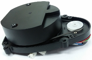
LDS-01
Overview


- 360 Laser Distance Sensor LDS-01 is a 2D laser scanner capable of sensing 360 degrees that collects a set of data around the robot to use for SLAM (Simultaneous Localization and Mapping) and Navigation.
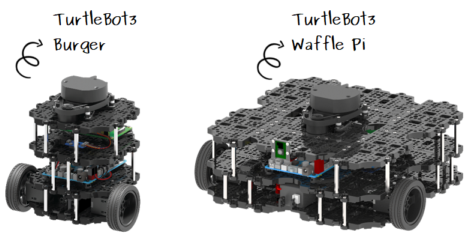
- The LDS-01 is used for TurtleBot3 Burger, Waffle and Waffle Pi models.
- It supports USB interface(USB2LDS) and is easy to install on a PC.
- It supports UART interface for embedded baord.
Introduction Video
- How to use the LDS-01
- Laser Distance Sensor (LDS) Example.
- ROS Hector SLAM demo using only a 360 Laser Distance Sensor LDS-01 made by HLDS (Hitachi-LG Data Storage).
- ROS Gmapping and Cartographer SLAM demo using TurtleBot3 and 360 Laser Distance Sensor LDS-01.
Specifications
General Specifications
| Items | Specifications |
|---|---|
| Operating supply voltage | 5V DC ±5% |
| Light source | Semiconductor Laser Diode(λ=785nm) |
| LASER safety | IEC60825-1 Class 1 |
| Current consumption | 400mA or less (Rush current 1A) |
| Detection distance | 120mm ~ 3,500mm |
| Interface | 3.3V USART (230,400 bps) 42bytes per 6 degrees, Full Duplex option |
| Ambient Light Resistance | 10,000 lux or less |
| Sampling Rate | 1.8kHz |
| Dimensions | 69.5(W) X 95.5(D) X 39.5(H)mm |
| Mass | Under 125g |
Measurement Performance Specifications
| Items | Specifications |
|---|---|
| Distance Range | 120 ~ 3,500mm |
| Distance Accuracy (120mm ~ 499mm) | ±15mm |
| Distance Accuracy(500mm ~ 3,500mm) | ±5.0% |
| Distance Precision(120mm ~ 499mm) | ±10mm |
| Distance Precision(500mm ~ 3,500mm) | ±3.5% |
| Scan Rate | 300±10 rpm |
| Angular Range | 360° |
| Angular Resolution | 1° |
Detail Specification Document
The following link contains information about basic performance, measurement performance, mechanism layout, optical path, data information, pin description and commands.
Here is the detail specification document : PDF
NOTE: The 360 Laser Distance Sensor LDS-01 for TurtleBot3 uses molex 51021-0800 and 53048-0810 instead of the basic housing and connector.
- [Connector for LDS] Molex 51021-0800
- [Connector for USB2LDS] Molex 53048-0810
LDS for TurtleBot3
The LDS-01 is used for TurtleBot3 Burger, Waffle and Waffle Pi models.

User Guide (for ROS)
We are offering ROS package for LSD. The hls_lfcd_lds_driver package provides a driver for HLS(Hitachi-LG Sensor) LFCD LDS(Laser Distance Sensor).
NOTE: Due to firmware update (after buy it on Oct. 2017), the sensor is running directly when power in on.
Installation
$ sudo apt-get install ros-kinetic-hls-lfcd-lds-driver
Set Permission for LDS-01
$ sudo chmod a+rw /dev/ttyUSB0
Run hlds_laser_publisher Node
$ roslaunch hls_lfcd_lds_driver hlds_laser.launch
Run hlds_laser_publisher Node with RViz
$ roslaunch hls_lfcd_lds_driver view_hlds_laser.launch
User Guide (for Driver)
- In addition to ROS, the LDS-01 supports Windows, Linux, and MacOS development environments for general purposes.
- The software requirement is:
- GCC (for Linux and macOS), MinGW (for Windows)
- Boost library (Lib for boost system, tested on v1.66.0)
Download
- Download the LDS-01’s driver
$ git clone https://github.com/ROBOTIS-GIT/hls_lfcd_lds_driver.git
- Or you can download directly on web browser at github repository below:
- Install dependent software and libraries for each development environment
- GCC (for Linux and macOS), MinGW (for Windows)
- Boost library
Build
- The makefile used here is set for Linux. Windows and macOS should be changed according to their development environment.
$ cd hls_lfcd_lds_driver/applications/lds_driver/
$ make
Run
- You can see the raw data in the terminal when you run the driver of LDS-01. Please check the source code for details.
$ ./lds_driver
r[359]=0.438000,r[358]=0.385000,r[357]=0.379000,...
User Guide (for GUI)
- We provide a basic GUI tool for visually checking the data of the LDS-01.
- It supports Linux, Windows, and macOS.
- The software requirement is:
- Qt Creator and Libs (tested on Qt Creator v4.5.0 and Qt Libs v5.10.0)
- GCC (for Linux and macOS), MinGW (for Windows), This can be installed together while installing Qt.
- Boost library (Lib for boost system, tested on v1.66.0)
Download
- Download the LDS-01’s driver and GUI source code.
$ git clone https://github.com/ROBOTIS-GIT/hls_lfcd_lds_driver.git
- Or you can download directly on web browser at github repository below:
- Install dependent software and libraries for each development environment
- Qt - Open Source Version
- GCC (for Linux and macOS), MinGW (for Windows)
- Boost library
Build
- Run the Qt Creator
- Open file (
Ctrl-O) thelds_polar_graph.profile (hls_lfcd_lds_driver/applications/lds_polar_graph/lds_polar_graph.pro) - Change the input your portname of source code
- Build all (
Ctrl-Shift-B)
Run
- Run the application (
Ctrl-R)

User Guide (for Embedded Board)
- We provide a way to connect to an embedded board.
- The data of the LDS-01 can be used on the embedded board like OpenCR and Arduino. Please refer to below instructions.
Preparations
- The LDS-01 in TurtleBot3 package comes with the interface board, but you can also connect the sensor to the power and UART pins of embedded boards.

WARNNING : The wiring colours of LDS-01 could differ from the picture by manaufacturers.
-
OpenCR develops and downloads firmware through the Arduino IDE. Therefore, you must install the Arduino IDE in advance and install the OpenCR board package. Install through the following link document.
Download firmware and run
- After connecting USB to PC, select
Tools->Board->OpenCR Boardin Arduino IDE. - Change
Tools->Portto the port to which the board is connected. - In the Arduino IDE Examples, select the firmware for LDS (
File->Examples->OpenCR->Etc->LDS->drawLDS). - Click
Uploadicon in the Arduino IDE that displays the red circle to build and download the firmware. When the download is completed, the firmware is automatically executed.
Certifications
Please inquire us for information regarding unlisted certifications.
FCC
Note: This equipment has been tested and found to comply with the limits for a Class B digital device, pursuant to part 15 of the FCC Rules. These limits are designed to provide reasonable protection against harmful interference in a residential installation. This equipment generates, uses and can radiate radio frequency energy and, if not installed and used in accordance with the instructions, may cause harmful interference to radio communications. However, there is no guarantee that interference will not occur in a particular installation. If this equipment does cause harmful interference to radio or television reception, which can be determined by turning the equipment off and on, the user is encouraged to try to correct the interference by one more of the following measures:
- Reorient or relocate the receiving antenna.
- Increase the separation between the equipment and receiver.
- Connect the equipment into an outlet on a circuit different from that to which the receiver is connected.
- Consult the dealer or an experienced radio/TV technician for help.
WARNING
Any changes or modifications not expressly approved by the manufacturer could void the user’s authority to operate
the equipment.


